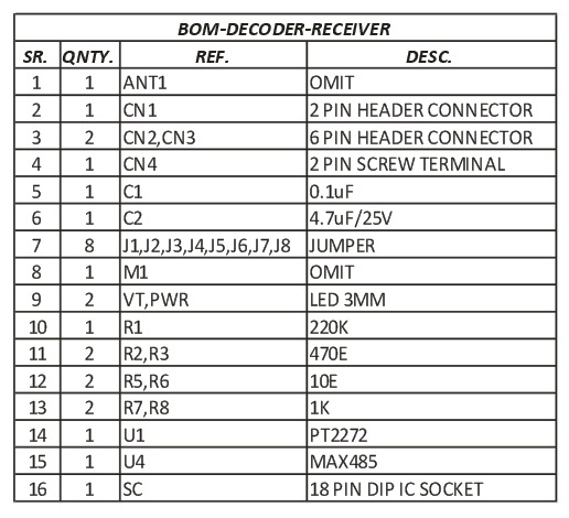
4 Channel 2 core twisted pair remote controller built using PT2262, PT2272-M4 IC from Princeton technology and MAX485 IC from Maxim. PT2262 is an Encoder (Transmitter), PT2272-M4 Decoder (Receiver) and MAX485 works as bridge for twisted pair communication between encoder and decoder. The receiver provides 4 channel Momentary outputs. All outputs are TTL level and can be interfaced with other circuits or relay board. Transmitter works with 5V to 12V DC. Receiver works with 5V DC.
When any of SW1-SW4 (S1-S4) tact switches is pressed, power is applied to encoder IC and RS485 IC, the encoder starts scanning Jumper J1-J8 and transmitting the status of the 8 bits address and data serially. The decoder IC receives the data from MAX485 and compares it two times with J1-J8 address jumpers, also provides outputs high and at same time VT (Valid Transmission) LED goes On, if the data is Valid and address of Transmitter and Receiver are same. It is important to have same jumper settings J1-J8 at transmitter and receiver to pair both.
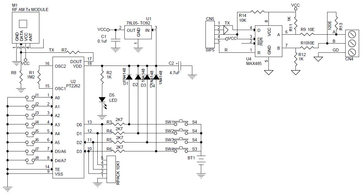
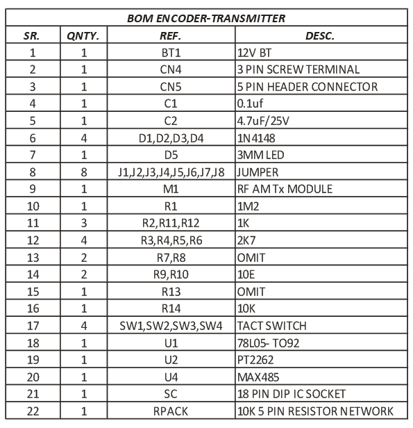
Encoder – Transmitter (PT2262)
PT2262 is a remote control encoder paired with PT2272 utilizing CMOS technology. It encodes data and address pins into a serial coded waveform. Circuit uses 8 bits of tri-state address pins providing up to 6561 address codes, thereby, drastically reducing any code collision and unauthorized code scanning possibilities.
PT2262 encodes the code address and data set into special waveform and outputs it to the DOUT when TE is pulled to low. The wave fed to RS485 IC for transmission. The transmitted RS485 IC data receive by receiver side of RS485 and PT2272 decode the waveform and set the corresponding output pin high. Thus completing a remote control encoding and decoding function.
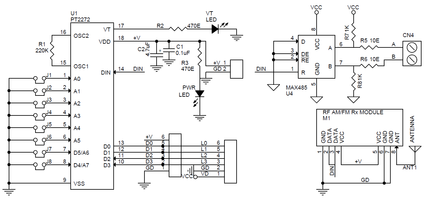
Decoder Receiver (PT2272-M4)
PT2272 decodes the waveform received and fed in to the DIN pin. The waveform is decoded into code word that contains the address, data and sync bits. The decoded address bits are compared with the address set at the address input pins. If both address match for 2 consecutive code words, PT2272 drives the data output pins whose corresponding data bits is the decoded to be a 1 bit, and (2) the VT output — to high state.
VT (Valid Transmission)
When PT2272 receive a transmission code word, it initially checks whether this is a valid transmission. For a transmission to be valid, (1) it must be complete code word, and (2) the address bits must match the address setting at the address pins. After two consecutive valid transmissions, PT2272 (1) drives the data pins according to the data bits received, and (2) raises VT to high state.
NOTE: J1 to J8 Jumper provided at Bottom layer of the PCB to set the address pins high. Top side of the PCB has Jumpers. Close them to set the address pins low for J1 to J8.
Features
Wide Range of Operation Voltage 5V to 12V Transmitter
Supply 5V DC Receiver
On Board Data Transmission LED
Single Resistor Oscillator
4 Momentary Outputs
4 Outputs TTL Level
Address setting 3 states HIGH, LOW, And FLOATING)
Remote provides 6561 addressable combinations by setting up J1-J8 to High, Low, and Floating.
On Board Power and Valid Transmission LEDS Receiver
Twisted Pair RS485 Communication Between Transmitter and Receiver
Milan, Italy, July 26, 2017 (Newswire.com) – Next Industries show off The Tactigon: the perfect link between humans or objects and the digital world, with its IMU 3D features, environmental sensors and Bluetooth 4.0 technology.
The Tactigon is a unique platform, programmable with Arduino IDE and expandable with GPS, LoRa or SIGFOX communication add on; it’s made for unlimited applications both in the industrial and in the consumer IoT worlds. Action, gesture, motion, and robots can be kept under control through a wearable, small but powerful electronic board. It is small, rectangular, with a lot of sensors inside, wireless, low powerconsumption and also wearable. With the above mentioned six features, this device is the perfect tool to test ideas and bring projects to life. The Tactigon measures linear and angular motion through 3 axis gyroscope and 3 axis accelerometer; an extra 3 axis magnetic sensor is included to provide more precision. Environmental sensors are on board, so temperature and barometric pressure data recording can be easily provided, like also out of the box communication through low energy Bluetooth 4.0, and optional available GPS, SIGFOX and LoRa.
Open Board for 3D Gesture Control, Motion Capturing, Tracking and Robotics – [Link]
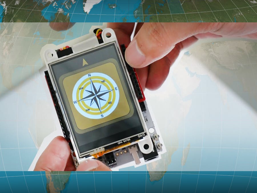
This project uses SmartEverything Development Board’s on-board iNEMO 9-axis intertial module to make a digital compass. by 4D Makers @ hackster.io:
The Digital Compass project uses the SmartEverything Development Board’s on-board iNEMO 9-axis inertial module specifically the 3D Magnetometer. The magnetometer module is sampled for the x and y axis readings and then computed its compass headings.
The project is partnered with the gen4-uLCD-24DT to graphically display a rotating compass, and accurately represent the compass heading.
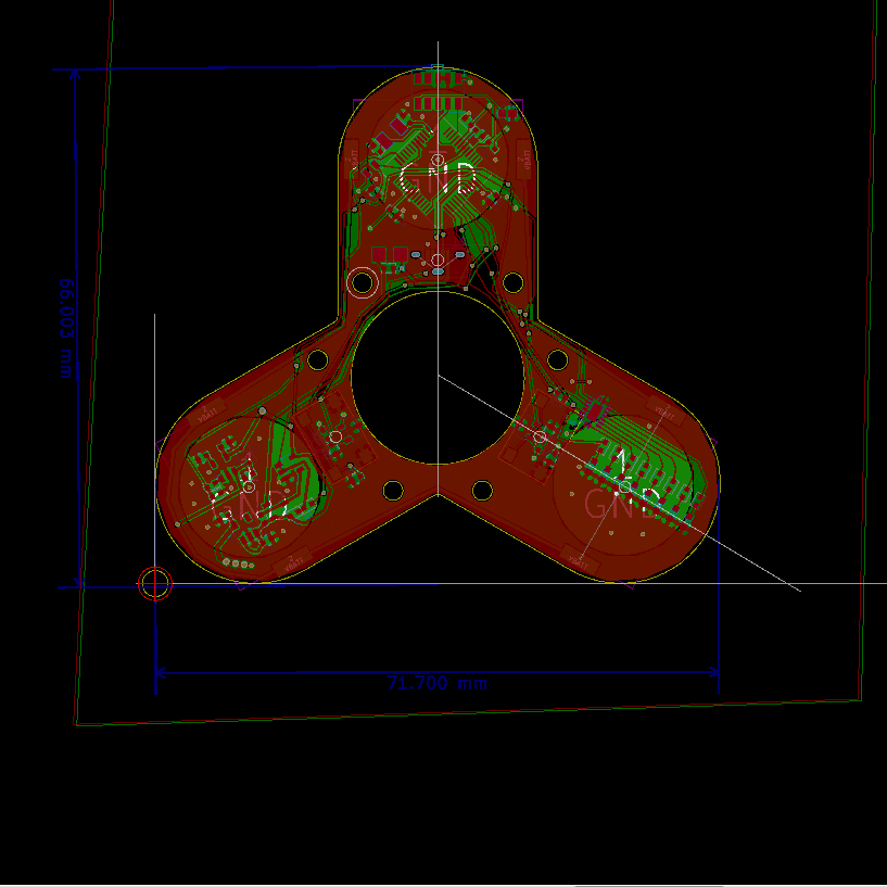
Fidget spinner became a popular toy earlier in 2017. Most of us have one or at least have tried it. Consists of a bearing surrounded by a three-lobed flat structure, it can spin along its axis with a little effort.
Makers and hardware hackers always try to employ different tools to make innovative ideas. Some of those makers hacked a fidget spinner to display custom text while it is rotating. The concept is using a vector of LEDs and turn them on and off at each degree according to the required text. Then, when it rotates very fast our eyes will see the full text as it is displayed together.
At this project on Hackaday, Sean Hodgins created a fidget-shape PCB that fits into the spinner. It consists of an 8-LED vector, a 32-bit microcontroller, an 8-bit shift register, and other electronics parts. It is powered by three 3.6 LiPo cell batteries and can be connected with PC through a micro USB connector.
The total cost is about $20 for all parts, and here is the bill of materials. Also the design of the fidget is available for 3D printing for both the body and the caps. In addition, the microcontroller can be programmed simply with Arduino IDE.
Since this project is fully open source, all resources and files are available for download. The github repository includes the CAD files, firmware code and libraries, PCB design, and some pictures.
Although it is a brilliant project, similar projects had been developed before and had started funding campaigns. But unfortunately, they weren’t successful and didn’t reach their fund goal.
Finally, if you like this idea you can make it by yourself with the help of this video, which describes how to make it and how it works:
Martina @ natural-nerd.com build a sound reacting LED light using Arduino:
Hi! In this build we’ll make a good looking light that dances to all sounds and music, using simple components and some basic Arduino programming. It makes an awesome effect while standing on the desk when gaming, playing music, and anything else that makes sound really. Let’s get going!
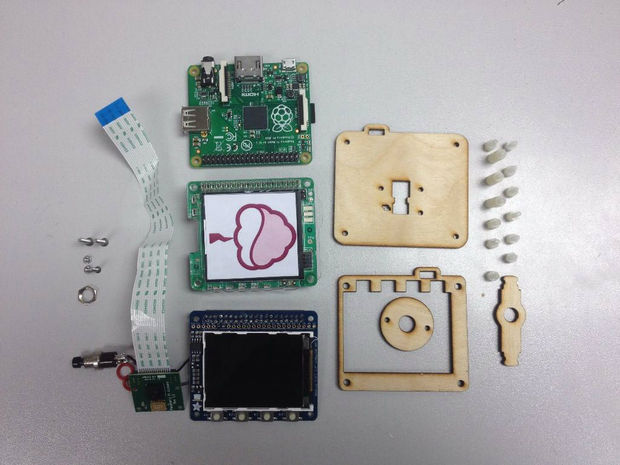
PiJuice at instructables.com designed an interesting compact camera project with raspberry pi. Raspberry Pi A+ is used in this project as it is the cheapest and smallest available Raspberry Pi. The real challenge in this kind of portable Pi projects is powering the Raspberry Pi. This issue is solved using PiJuice—an all in one battery module for the Raspberry Pi.
Required parts to make Raspberry Pi compact camera
Set Up The Raspberry Pi
Download the latest version of the Raspbian image from the Raspberry Pi Website and burn it on your blank SD card. You can use win32DiskImager or your favorite software to get the job done. Now, you need to install the drivers for the TFT screen by running the DIY installer script, explained on the Adafruit page. Connect the TFT to the Raspberry Pi, attach the PiJuice with a charged battery, and switch it on. Your screen now should display boot up messages.
Connect The Camera
Insert the ribbon cable of your camera module properly ensuring that the blue side of the ribbon is facing away from the HDMI port. Now, go to the terminal and type the following command,
sudo raspi-config
Enable the camera in the menu and then reboot the Pi. The camera should work properly after a successful reboot. To test the camera, enter the following command:
raspistill -o pic.jpg
This will take a snap and save it in the /home/pi directory.
Connect A Push Button
You need a push button to simulate a shutter action. Locate the pin 17 on the GPIO breakout on the top of the TFT screen. Now, solder two wires to the terminals of the push button. You can either solder a right angle header to the pin 17 or you can directly solder one wire from push button to that pin. There is a pad labeled WP on the board. It is actually connected to the ground. Solder another wire from the push button to this pad.
Install And Test The PiCam Software
To install the software, the Raspberry Pi must be connected to the internet. Enter the commands given below to download and install PiCam.
Once the software has been downloaded, navigate to the PiCam directory using the command:
cd /picam
You can run it by typing the command:
sudo python picam.py
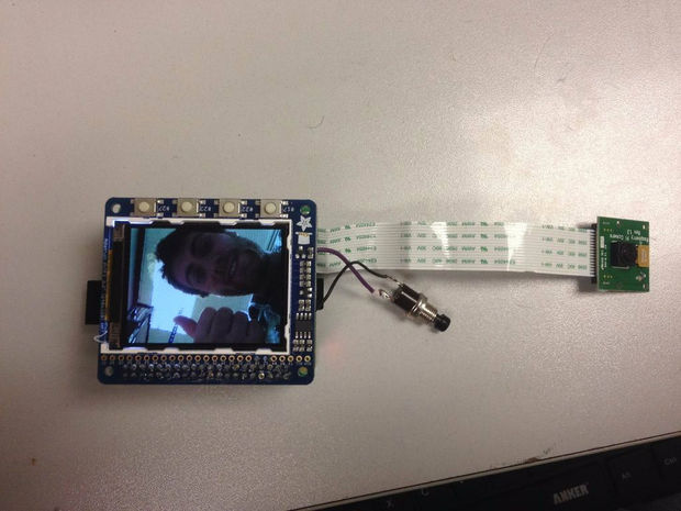
Now, you can take pictures by simply pressing the push button. Once the button is pressed the picture will be taken. Once the captured image gets loaded, your photograph will be displayed.
Taking photograph with Raspberry Pi compact camera
Conclusion
Your Raspberry Pi camera is ready now. If you want to make it even more compact as well as portable, grab the official laser-cut compact camera case from the Kickstarter page by pre-ordering a Maker Kit. You can also build your own simple chassis for housing the camera.
In IoT and digital age, location-based services applications are widespread: starting from Google maps to anti-loss devices and not ending with location-based marketing. The most common technologies used for user location identification are: GPS, WiFi and Beacons (a custom BLE profile).
Location-based (geofencing) marketing is a new way to enhance the personal experience while shopping. For example if you were near the shampoo section you will get on your mobile exclusive offers about that section.
Choosing the right location detection technology needs to take into consideration that GPS works optimally in the open sky environments and WiFi and Beacons can work probably indoors (and outdoors but within inhabited areas with hotspots). Now let’s get a brief look at each technology:
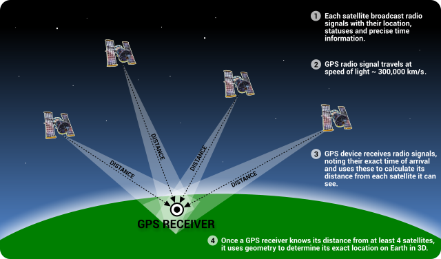
GPS
Thanks to on-the-shelf GPS modules/receivers from vendors like: Neoway and u-blox it’s easy to embed a GPS receiver into your project. What you need is a module sending its messages via UART to the MCU and a ready-made antenna attached to the module. There is a standard format for these modules messages called NEMEA. These messages contain information about the location that includes longitude, latitude, direction, speed … etc. These receivers need to see at least 4 satellites to compute a position.
There are many navigation systems like the Russian GLONASS, the European Union’s Galileo and the American GPS.
GPS is mainly designed to be an outdoor location detection system. Therefore, its performance decreases in enclosed places and across crowded areas with buildings.
WiFi
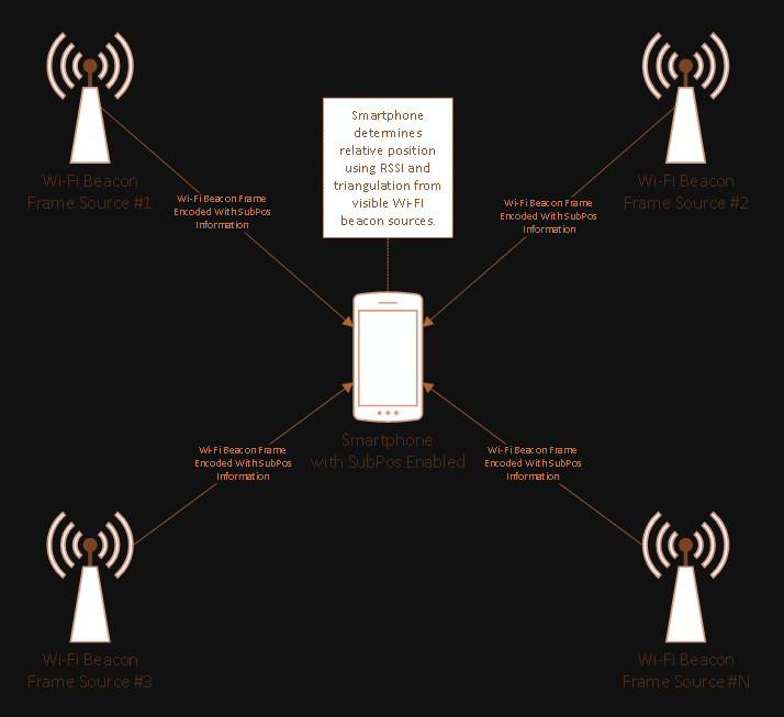
WiFi can be used in location detection (AKA Wi-Fi positioning system) when your phone or WiFi transceiver module like ESP32 or ESP8266 is near hotspots. You can consider WiFi like a coexisting system with GPS for indoor areas. Moreover, WiFi can be used to detect the location inside the enclosed/underground area; you can see the SubPos project on Hackaday to know how.
Location detection systems using WiFi use techniques based on received signal strength indication (RSSI), angle of arrival (AoA) and time of flight (ToF). You can read more about these techniques from the Wikipedia article.
Bluetooth Beacons
Beacon technology is enabled by Bluetooth Low Energy (BLE) and it’s one of the BLE custom profiles. Beacons are used for proximity-aware applications like positioning indoors, and for location based advertisements. The idea behind this technology is to calculate the distance between the receiver and the transmitter by calculating the difference between the power of the sent and received signal (comparing the Received Signal Strength Indicator (RSSI) to a transmit (Tx) power). Knowing that, the power information is available in Apple iBeacon advertising packet (for example).
LucaBellan @ open-electronics.org re-created the Ambilight TV effect on any other TV using Raspberry and Kodi. He writes:
The screen’s edges are divided into logic sectors, and each sector is associated with a specific LED and, by making a color average of the pixels, you can find the color to set to be reproduced by the LEDs; this operation is repeated for all the LEDs mounted on the TV and all of this is repeated hundreds of time per second in order to provide synchronicity and maximum smoothness to the colors projected around the TV.
With RaspiLight we can re-create this technology and apply it to any flat-screen TV, but there’s more: even when the TV is off, we can control the system through an Android or iOS app and create static or dynamic light effects and make the TV an animated lighting point and not just a simple lighting piece of furniture.
RASPILIGHT: an open project for Ambilight TV effect – [Link]
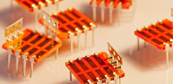
Bismuth is considered as a “green-element” and bismuth-based compounds are gaining attention as potentially non-toxic and defect-tolerant solar absorbers. The researchers of the University of Cambridge and the United States developed theoretical and experimental methods to show that bismuth, which sits next to lead (Pb) on the periodic table, can be used to make inexpensive solar cells.
Bismuth oxyiodide light absorbers
The study suggests that solar cells including bismuth can have all the exceptional properties of lead-based solar cells but without any worries about toxicity. Another study by a different group discovered that bismuth-based solar cells have the ability to achieve a conversion efficiency of 22% which is comparable to the conversion efficiency of most advanced solar cell available in the market.
Many of the new materials recently investigated show limited photovoltaic performance. Bismuth Oxyiodide (BiOI) is one such compound and it is explored in detail through theory and experiment. Most of the solar cells commercially and domestically used are made from silicon (Si) which is efficient enough but has very low defect tolerance compared to bismuth oxyiodide. Low defect tolerance in silicon implies that the silicon needs to have very high levels of purity, making the production process energy-intensive.
Over the past several years researchers have been looking for an alternative to silicon for making solar cells cost effectively. The most promising group of these new materials are called hybrid leadhalide perovskites. Unlike silicon, they don’t need such high purity levels. Hence, production is cheaper. But, the lead contained within perovskite solar cells represents a definite risk to all living beings and the environment. So, scientists are searching for non-toxic alternatives without compromising the performance.
Dr. Robert Hoye of Cambridge’s Cavendish Laboratory and Department of Materials Science & Metallurgy said,
We wanted to find out why defects don’t appear to affect the performance of lead-halide perovskite solar cells as much as they would in other materials.
The researchers are trying to figure out what’s special about the lead halide perovskites so that they can replicate their properties using non-toxic materials like bismuth.
Their research found that bismuth oxyiodide is as defect tolerant as lead halide perovskites are. Another interesting fact is, bismuth oxyiodide is stable in air for at least 197 days which is even better than some lead halide perovskite compounds. By sandwiching the bismuth oxyiodide between two oxide electrodes, the researchers successfully converted 80% of light to electrical charge.