Introduction
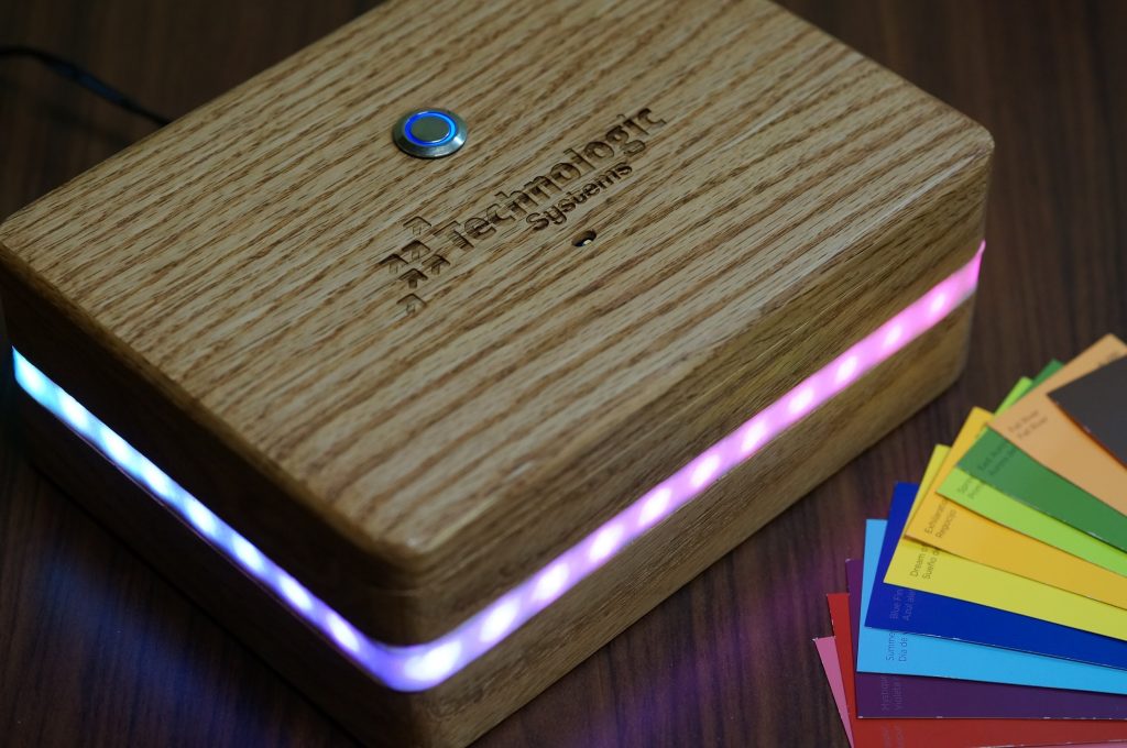
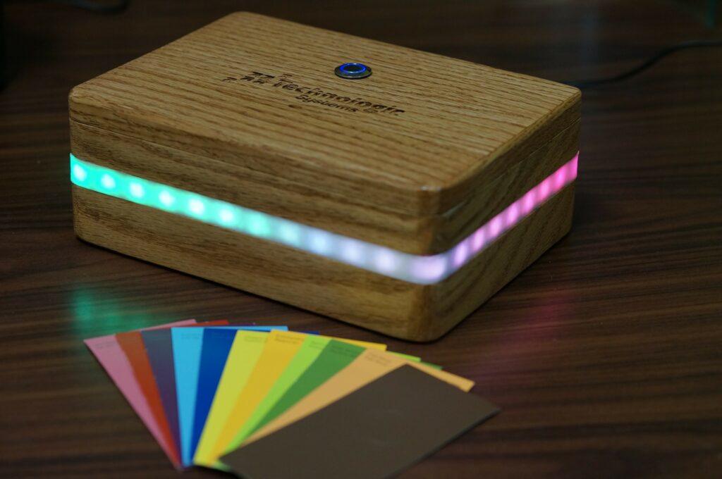
Besides looking damned good on an otherwise bland and ordinary desk, this project is about more than just being attention grabbing eye candy. It’s about demonstrating a small portion of our single board computer capabilities by hooking up a color sensor, RGB light strip, and enclosing it in a nice looking wooden enclosure. We’re dubbing it the “aurora boxealis”, and it’s made to stand out from the crowd at trade shows and provide a fun, interactive way to professionally demonstrate an interesting sensor, in this case a color sensor. Grabbing a color swatch from the table and placing it on the top of the box will trigger the lights to mirror that color.
Furthermore, with inspiration from the Celebrationator from “Cloudy with a Chance of Meatballs”, it has a party mode of dancing disco lights which is triggered by pressing the party button on top.
When it’s not partying or matching colors, it displays a calming, color changing effect somewhat reminiscent of the aurora borealis. Take a gander at a full demonstration over on our YouTube channel and then come back for the following details on the build below.
Hardware

The stars of the show are the TS-7970 single board computer, TCS34725 color sensor, FadeCandy RGB LED driver, and RGB LED light strip (WS2811 based). The TS-7970 provides the I/O, power, and processing for the color sensor, FadeCandy, and light strip. The color sensor has everything built-in, including a bright white LED and IR filter. It has an interrupt pin and settings for interrupt thresholds based on the clear light value it reads. The FadeCandy driver is a clever little piece of hardware that utilizes software and firmware to maximize the performance of the RGB LEDs, like for example, color correction and dithering for fantastic color depth. Take a look at their respective product pages for more information. Finally, a button was hooked up to an interrupt pin on the TS-7970 for starting a party.
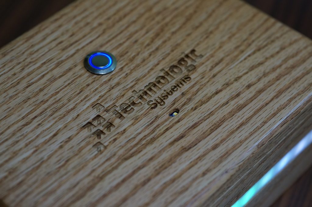
Everything has been enclosed inside a custom-made wooden enclosure with the light strip and diffuser wrapped all around. The color sensor and button are mounted on the lid for easy access. A power barrel connector is cleanly installed on the back of the unit. Here’s the wiring diagram for how it’s all hooked up.
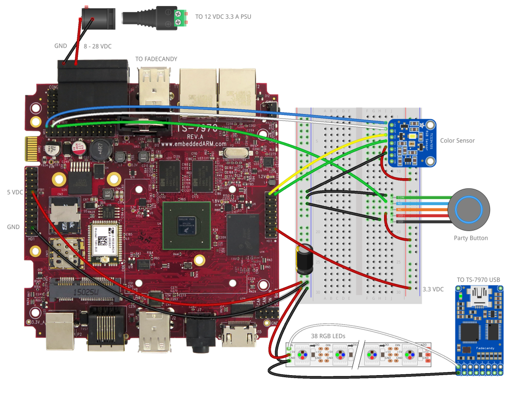 HD1 – 24 PIN
- Attaches to LED strip
- Pin 3 – Ground – Black
- Pin 15 – 5V Power – Red
HD2 – 24 PIN
- Attaches to RGB sensor and button
- Pin 2 – GPIO#64 (LED Enable) – Blue
- Pin 4 – GPIO#65 (Sensor Interrupt) – White
- Pin 6 – GPIO#66 (Button Interrupt) – Green
HD3 – 16 PIN
- Attaches to RGB sensor and button
- Pin 3 – 3.3V Power – Red
- Pin 15 – SCL (I2C Clock) – Green
- Pin 16 – SDA (I2C Data) – Yellow
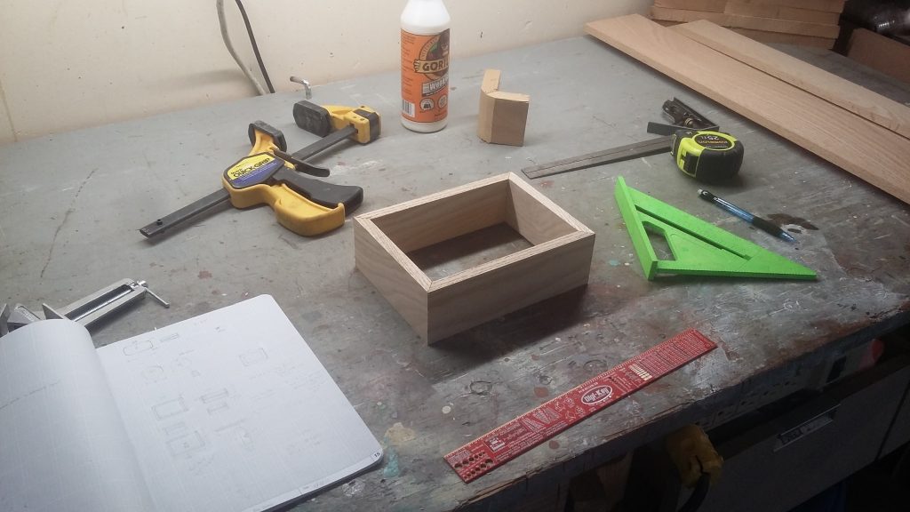
The box itself is made from oak hobby board purchased at a local hardware store. The mitered corners are glued together using some high-strength wood glue. The cap was spliced together using biscuits and edged with thin pieces of oak. Holes were drilled for the button, power adapter, and color sensor. For the rectangular color sensor PCB, a chisel was used to chip out a rectangular spot for the sensor to fit in. A ¼” thick and ¼” deep gap was routed into the middle of the box for the LEDs. A ½” thick, very shallow gap was routed into the middle as well for the diffuser material to sit on. A panel board was used for the bottom and the TS-7970 was mounted to it using custom wooden standoffs. Everything was rounded off and finished up on the bench router before sanding and staining the final product. The result was a very nice, travel-ready, oak box with detachable lid.
Software
 First off, let’s acknowledge how awesome the open source community is. Most of the legwork was already completed and packaged up for use with Python, including GPIO sysfs interface with interrupt support, TCS34725 support, and plenty of FadeCandy examples which work with Open Pixel Control (OPC). The only thing that was left to do was figure out how to use the Twisted reactor used with the GPIO sysfs interface code for handling interrupts. Admittedly, this did add a layer of complexity to the code which took a little while to comprehend, but once the learning curve is overcome, it’s not a bad way to go.
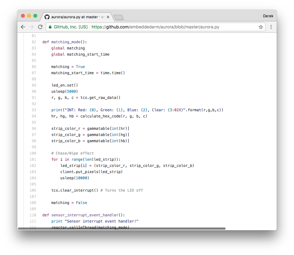
Now, let’s talk about the source code, located at https://github.com/embeddedarm/aurora. The main file is aurora.py, which utilizes a bunch of different libraries including:
- Adafruit TCS34725 – Uses smbus for I2C communication and provides a bunch of handy functions for interfacing with the color sensor.
- Python Sysfs GPIO – Provides a bunch of handy functions for interfacing with the GPIO pins that are brought out using the Linux GPIO sysfs interface. Includes interrupt support by using Twisted.
- Open Pixel Control (OPC) – Sends pixel values to an Open Pixel Control server, in our case FadeCandy, to be displayed.
- FadeCandy Server – A separate process running in the background which receives instructions from OPC and lights up the RGB LED strip.
- Pillow – Used to process images used for party (party.jpg) and chill (chill.jpg) modes.
Don’t worry, this won’t be a deep dive. Instead, we’ll discuss a few highlights of the code. As mentioned, we’re using the Twisted reactor to handle GPIO interrupt events, threading, and provide our main while loop via LoopingCall(main). The program starts with the call to reactor.run(). We use a bunch of global variables to keep track of the different states we’re in, including party, chill, or matching. We do this as a simple way to break out of the thread, mainly because there’s no other easy way to stop a threaded processes in Python.
For example, let’s say we’re chilling in our display_image(‘chill.jpg’) thread, which will last until the for loop has finished processing the image top to bottom only to be called again in a forever loop by our main looping call. Then, somebody comes along and presses the party button. This fires a system event for the GPIO interrupt and sets the global variables to break out of the chill loop so we can start the party loop. Same sort of thing for the matching mode when somebody places a color swatch above the color sensor.
Before calling the main loop, we initialize the GPIO pins, color sensor, OPC client, and event triggers.
First, we setup our GPIO pins:
Controller.available_pins = [LED_EN, RGB_INT, PTY_BTN]
led_en = Controller.alloc_pin(LED_EN, OUTPUT)
sensor_int = Controller.alloc_pin(RGB_INT, INPUT, sensor_interrupt_fired, BOTH)
button_int = Controller.alloc_pin(PTY_BTN, INPUT, button_pressed, FALLING)
The LED_EN (LED Enable) output pin controls the LED mounted on the color sensor, which is normally on. We only want it to turn on when we’re ready to color match. The two interrupt pins, sensor interrupt and button interrupt, are set up as interrupts with callback functions.
Next, the color sensor gets initialized and the interrupt pin and tolerances are set:
tcs = Adafruit_TCS34725.TCS34725()
tcs.set_persistence(TCS34725_PERS_10_CYCLE)
tcs.set_interrupt_limits(0x0002, 0xFFFF)
tcs.set_interrupt(True)
What we’re saying here is, set the interrupt pin if the clear color is outside the limits of 0x0002 (very dark) to 0xFFFF (max light) in a period of 10 readings.
Then, we setup our OPC client.
client = opc.Client('localhost:7890')
client.put_pixels(black)
client.put_pixels(black)
We set the client to connect to localhost, port 7890, served by the Fadecandy server, fcserver. This is what drives the addressable RGB LEDs of the NeoPixel strip. To start, we want to make sure all pixels are black.
For debugging, it’s handy to have a signal handler to help cleanly kill off the program when Ctrl+C is hit on the keyboard.
signal.signal(signal.SIGINT, signal_handler)
Next, we setup our system event triggers for the Twisted reactor.
reactor.addSystemEventTrigger('before', 'sensor-interrupt', sensor_interrupt_event_handler)
reactor.addSystemEventTrigger('before', 'button-interrupt', button_interrupt_event_handler)
We can then call, for example, reactor.fireSystemEvent(‘button-interrupt’), and the callback function button_interrupt_event_handler() will be called.
Finally, we set up and start our main looping call and fire up the reactor to kick everything off.
lc = LoopingCall(main)
lc.start(.1)
reactor.run()
Closing Remarks
Overall, this was an incredibly fun and rewarding project, combining two passions of woodworking and computer engineering into one end result. That end result being an attractive, out of the ordinary product that will grab attention while showing off a really neat sensor and some of the capabilities of our TS-7970.
There’s certainly room for expansion in the future as well, like adding a microphone and speaker and interfacing with Google Voice Actions or Amazon Alexa Voice Service to make a voice-controller home appliance and music box. Control the color of the lights by speaking to it or set up the lights to dance to the music it plays. Add other sensors to the box, like a gesture sensor, to come up with other clever things, like controlling lights or thermostats in your IoT connected smart home.
I do hope you enjoyed this project and will share it. I’m anxious to hear your thoughts, so be sure to leave a comment below. Until next time, party on!
Sources
- https://github.com/embeddedarm/aurora
- https://github.com/adafruit/Adafruit_Python_TCS34725
- https://github.com/derekstavis/python-sysfs-gpio
- https://python-pillow.org/
- https://learn.adafruit.com/chameleon-scarf/code
- https://github.com/scanlime/fadecandy
- http://github.com/zestyping/openpixelcontrol
- http://twistedmatrix.com/trac/
Materials
Here’s a detailed list of everything needed to build this project. Not including the cost of the SBC or shipping, this project costed approximately $157.42, and that’s if you’re starting from scratch. Most will have the necessities like bread boards, wiring, and solder. Some will have spare stain, poly, glues, and wood for the box build.
- TS-7970 Single Board Computer – $272.00
- Adafruit Mini Skinny NeoPixel Digital RGB LED Strip – 60 LED/m – $24.95
- FadeCandy – Dithering USB-Controlled Driver for RGB NeoPixels – $24.95
- RGB Color Sensor with IR filter and White LED – TCS34725 – $7.95
- Rugged Metal Pushbutton with Blue LED Ring – 16mm Blue Momentary – $4.95
- Panel Mount 2.1mm DC barrel jack – $2.95
- Male DC Power adapter – 2.1mm plug to screw terminal block – $2.00
- USB Mini-B Cable – 6″ – $1.95 – For connecting the FadeCandy driver board.
- 3x 24 Position Rectangular Socket Connector IDC Gold – $0.68 ea. – Somewhat fragile. I’d recommend ordering extras.
- 16 Position Rectangular Socket Connector IDC Gold – $0.36 ea. – Somewhat fragile. I’d recommend ordering extras.
- Conn Header Vert 24 Pos Gold – $0.52 – To solder to proto board for easy disconnect.
- Breadboard – $4.95 – For quick testing and prototyping.
- SparkFun Snappable Protoboard – $7.95 -Any protoboard would work, but this is handy to snap to size.
- Electrolytic Decoupling Capacitors – 1000uF/25V – $0.35 – One of these is recommended to protect NeoPixel strip from surge of power.
- Hook-Up Wire – Assortment (Stranded, 22 AWG) – $16.95 -I’d recommend a smaller gauge wire for the IDC connectors.
- Jumper Wires – Connected 6″ (M/F, 20 pack) – $1.95 -For quick testing and prototyping with the breadboard.
- Solder Lead Free – 100-gram Spool – $7.95
- 2x Oak Hobby Boards – ~$8.25 ea. – ½” thick, 2 ½” wide, 36” long ought to do it. Couldn’t find it online, but it exists in the store.
- Acrylic panel (Home Depot PN#340-453) – $10.98 – For diffusing the LEDs, you’ll only need a very small amount of this. Try finding damaged stock and get a discount. I got it for 50% off because of a broken corner.
- DAP Weldwood 3 fl. oz. Original Contact Cement – $4.95 – For adhering the LED strip to the wood.
- Loctite 2-In-1 Seal & Bond Adhesive Caulk, Clear, 5.5-oz. Tube – $3.29 – For adhering the diffuser.
- Minwax 8 oz. Wood Finish Cherry Oil-Based Interior Stain – $4.78
- Minwax 8 oz. Satin Fast-Drying Polyurethane – $6.48
- Gorilla 18 fl. oz. Wood Glue – $5.97 – A very good bonding glue to avoid the use of nails in the box build.