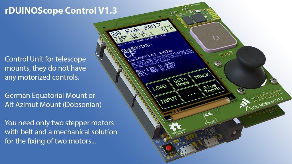
Dessislav Gouzgounov @ hackaday.io build an Arduino Due based, open source, goto telescope controller.
The initial idea was to create cheap and easy to build alternative of commercially available GOTO hand controllers, but in a better, feature rich way. In the heart of the system is the rDUINOScope Software, some 2500 rows, controlling all HW components and handling communication with external devices (Stellarium, SkySafari and others) .
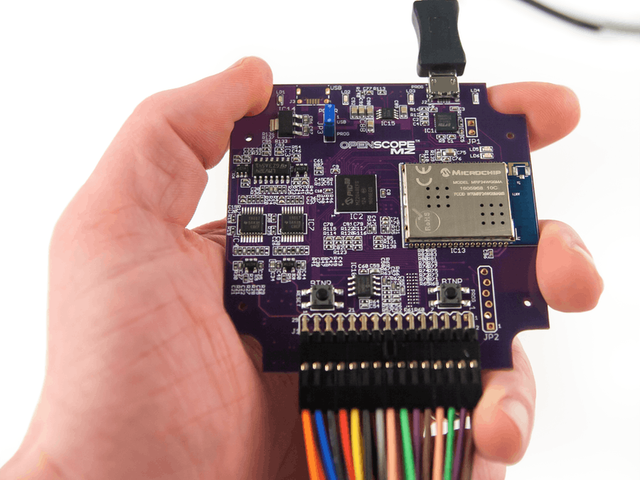
This project will show how to use your OpenScope MZ in LabVIEW. by Austin Stanton @ hackster.io:
In this tutorial, we will go over how to connect an OpenScope MZ to LabVIEW. To do so, I will be walking you through some example VIs that I made. These examples allow you to access the oscilloscope and Wavegen/DC power supply functions of the OpenScope as well as the GPIO pins and the Logical Analyzer.
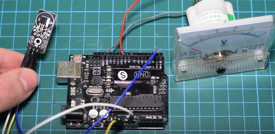
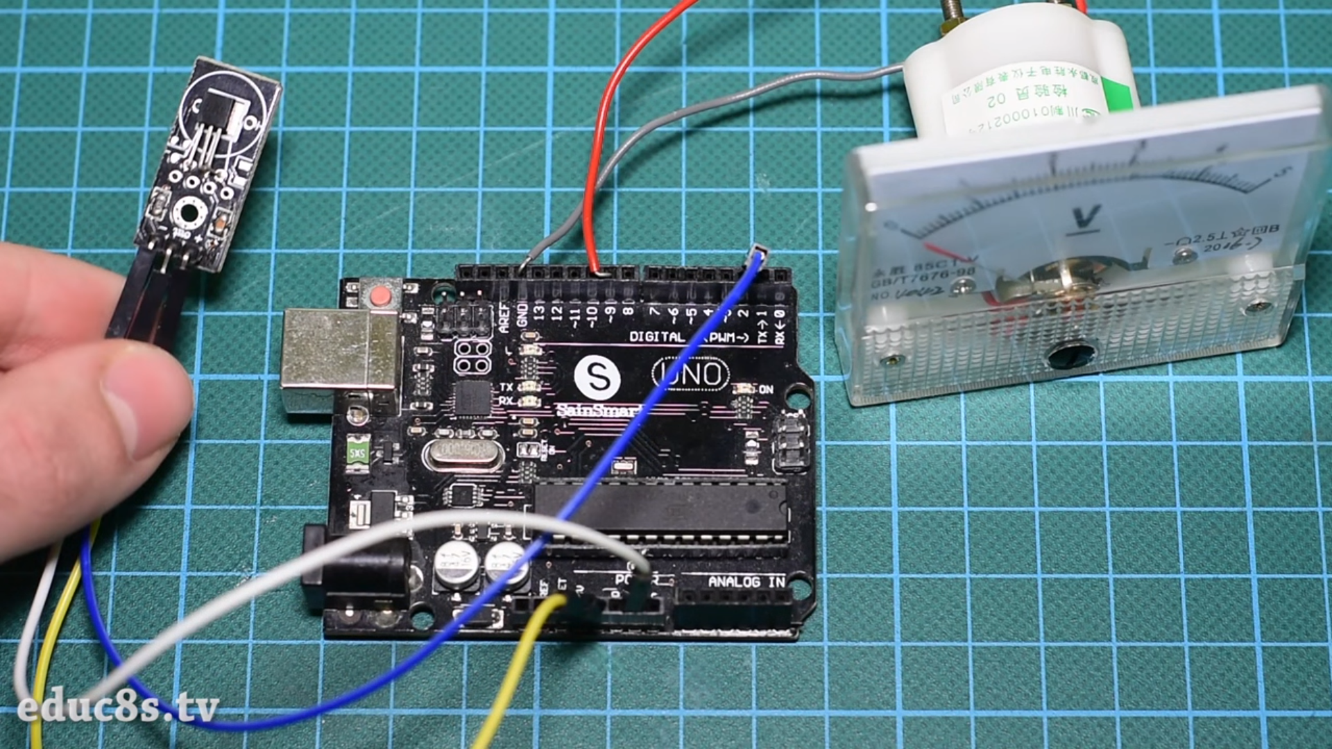
Sometimes, it is necessary to add a temperature indicator into your projects. Therefore, in this tutorial you will learn how to hack your analog Voltmeter and convert into an analog Thermometer using Arduino and a DS18B20 temperature sensor.
Arduino Analog Thermometer With DS18b20 Module – [Link]
Sometimes, it is necessary to add a temperature indicator into your projects. Therefore, in this tutorial you will learn how to hack your analog Voltmeter and convert into an analog Thermometer using Arduino and a DS18B20 temperature sensor.
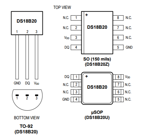
DS18B20 Module
In the first place, the Maxim DS18B20 digital thermometer provides 9-bit to 12-bit Celsius temperature measurements and has an alarm function with nonvolatile user-programmable upper and lower trigger points. Also, the DS18B20 communicates over a 1-Wire bus that by definition requires only one data line (and ground) for communication with a central microprocessor. In addition, the DS18B20 can derive power directly from the data line (“parasite power”), eliminating the need for an external power supply.
In fact, each DS18B20 has a unique 64-bit serial code, which allows multiple DS18B20s to function on the same 1-Wire bus. Thus, it is simple to use one microprocessor to control many DS18B20s distributed over a large area.
Fortunately, the circuit is so simple. At the beginning, connect the DS18b20 pin with the (-) sign to Arduino GND, the pin with (+) sign to 5V and the signal pin to digital pin 2, in order to start sensing the temperature.
Secondly, in order to control the voltmeter we connect the positive side to digital pin 9 (one of the PWM pins) and the negative to GND. Afterward, to change the labels of voltmeter to a Celsius thermometer, just download the photo in the attachments and print it out!
source: educ8s.tv
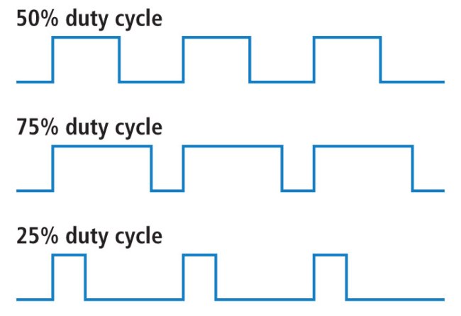
Pulse Width Modulation
In a nutshell, Pulse Width Modulation, or PWM, is a technique for getting analog results with digital means. Therefore, instead of writing high to the digital pin in PWM, we can send a pulse. Accordingly, some digital pins of Arduino UNO support PWM and you can recognize them by this signal (~) printed beside.
The Code
First of all, you need to add “DallasTemperature” library to your Arduino IDE, since it is a library that supports Maxim temperature ICs including our DS18B20.
The code consists of three main ideas:
Reading the temperature from the sensor.
Converting the temperature into a PWM value
Showing the value on the thermometer
First, in the setup we will read the temperature from the sensor. Then, we will pass it to the PWM function to convert the acquired value into a PWM value within the range of 0 to 255. This can be done inside the function with the help of “map” function. Next, we will write it into pin 9 to be shown on the voltmeter.
However, you can assign your preferable minimum and maximum temperature degrees, but you should notice: the smaller the gap between those two values, the bigger the resolution of the thermometer.
Let’s have a look at the code:
//Written by Nick Koumaris
//info@educ8s.tv
//educ8s.tv

#include <OneWire.h>
#include <DallasTemperature.h>

#define ONE_WIRE_BUS 2

OneWire oneWire(ONE_WIRE_BUS);
DallasTemperature sensors(&oneWire);

int MIN_TEMP = 16;
int MAX_TEMP = 28;

void setup() {

pinMode(9,OUTPUT);
Serial.begin(9600);
sensors.begin();

}

void loop() {

  float temperature = getTemperature();
  int voltage = temperatureToPWM(temperature);
  analogWrite(9,voltage);
  delay(500);
}

float getTemperature()
{
  float temperature =0;
  sensors.requestTemperatures(); // Send the command to get temperatures
  temperature = sensors.getTempCByIndex(0);
  Serial.println(temperature);
  return temperature;
}

int temperatureToPWM(float temperature)
{
  float temp=0;
  float voltage = 0;
  temp = temperature*10;
  voltage = map(temp,MIN_TEMP*10,MAX_TEMP*10,0,250);
  return voltage;
}
Finally, this tutorial is made by educ8s.tv channel, and you can find the tutorial video below:
So it’s the time to witness the birth of a new certification for IoT industry. As security and data privacy in IoT platforms and products are two of the main concerns for developers and end-users, the new certificate discuss these concerns and even more. IoT is yet to have such certificate, as best of my knowledge, to pave the road to standardize the rules of openness and privacy in IoT. Although the term of IoT certification is already there, and some companies can do security test for your IoT products and certificate it, but nothing seems to analogy to certificate like open source hardware certificate, where anyone meets the principals, can use the OSH mark on his product.
Image courtesy of IoT.do
The new certification IoTMark was the output of a meetup hosted on June 16th 2017 in UK. This meetup gathered over 60 participants from UK and Europe. Specifically, a 22-page-long document was the output from this meetup. This document contains the principles of the certificate:
…
The supplier of this product or service MUST be General Data Protection Regulation (GDPR) compliant.
This product SHALL NOT disclose data to third parties without my knowledge.
I SHOULD get full access to all the data collected about me.
….
Interoperability
…
Have an open platform API [MUST]
Provide comprehensive platform API documentation [MUST]
…
The preparation for the certificate didn’t finish yet, where The folks behind this certification will finalize it and register the mark by December 2017.
Don’t forget to have a look at the full document here. Who knows; You could use it in your next product. It’s really worth to give it a bid!
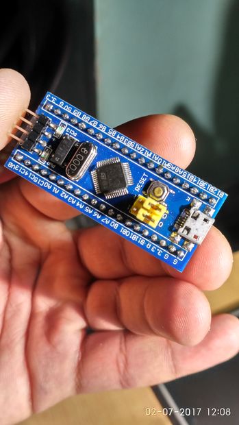
HardiqV@ instructables.com build an alternative board to Arduino using STM 32 series of mcus.
We love the Arduino board and it’s prototyping platform . It makes the complete prototyping process smooth and enjoying with the help of it’s add on such as Arduino IDE and a huge community support.But sooner or later you will find that the specifications provided by the arduino boards is not enough . And then the problem arises about which board should we use so that our desires are fulfilled.Also How easy is to use a non arduino board . After a good research I found that the STM 32 is perfect fit.
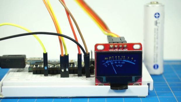
techn0man1ac@ instructables.com build a nice VU meter using Arduino and an OLED display.
Hello, instructable. Today I will tell you how to make a simple digital VU meter (sound level meter) using Arduino and OLED displays and 2 resistors by yourself (DIY). The device is quite simple, for beginners it will be a rewarding experience.
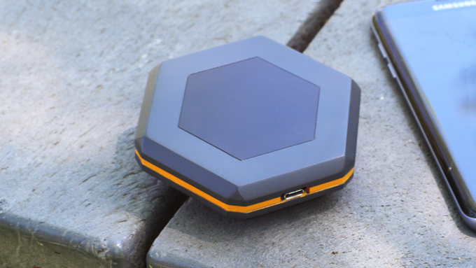
At Sonnet Labs, a group of avid outdoor enthusiasts aim to democratize mobile communication with technologies that enable smartphones to send text messages, image data, and GPS locations without Internet connectivity, cellular coverage, or satellite reception.
No need for cellular grid with Sonnet
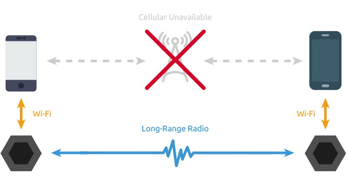
Therefore, they launched their product, Sonnet, the smartphone walkie-talkie! Sonnet is a wireless device that brings the long-range wireless communication capability of the 2-way radio (walkie-talkie) to smartphones. In addition, it enables device-to-device data transfer through low-power, long-range radio frequencies dependently on cellular grids and infrastructures.
Accordingly, Sonnet can connect wirelessly to any smartphone. Also, it allows sending data up to many miles in distance to other smartphones that already are using Sonnet.
More features to come…
Sonnet uses mesh networking in order to reach users out-of-point relaying on sending data privately through other users in area. This data travelling through Sonnet is already end-to-end encrypted with AES. At the same time, the Sonnet Wi-Fi connection is protected with WPA/WPA2.
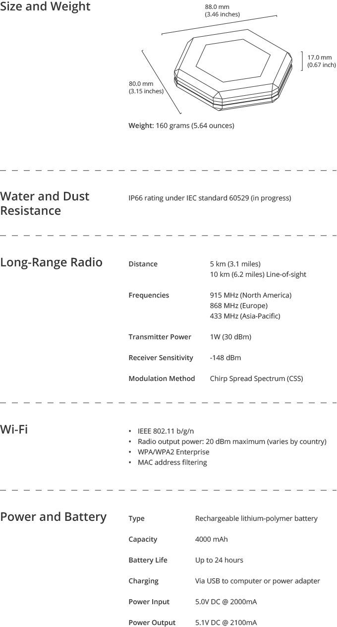
It also has the ability to charge your phone. Thanks to the 4000mAh battery capacity, Sonnet can charge your smartphone through its USB port.
Moreover, you don’t need to install software in your smartphone. It is enough to have an access to the app through your browser. The team tailored this feature to allow users who don’t have internet access to use the device easily.
Above all, one of the amazing features included is SOS mode. In case of emergencies. you can press the panic button. Next, Sonnet will send your GPS location and your message to all users in range.
Full specifications of Sonnet below:
In conclusion, Sonnet is the wireless device that enables you send instant messages, voice recordings, image data and GPS coordinates even if you don’t have cellular coverage or Internet access.
Sonnet is now live on a Kickstarter campaign and has already achieved 290% of its required funds. The campaign still has 28 days to go, where you can pre-order two pair of Sonnet for $89! Also check the official website for more details.
andersDX has added a round AMOLED (Active Matrix OLED) display to its range for wearable and instrumentation applications, complementing the circular PMOLED and touchscreen modules that it already offers.
1.3” circular AMOLED modules only 0.6mm thick – [Link]
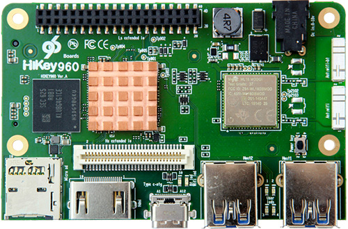
A development platform for the Android open source project (AOSP) has been created by Huawei. The ARM-based hardware is part of the Linaro open source collaborative engineering organization developing software for the ARM ecosystem.
Recently, Huawei has launched the HiKey 960 96Boards development platform to provide access to the latest ARM mobile technology for AOSP developers. Fortunately, You can find this new board listed on the 96Boards website and is available through global distribution channels.
In fact, initial software support for the board is provided in the AOSP source tree based on the Android Common Kernel using the Linux 4.4 kernel release. Meanwhile, Linaro and Huawei are also working on the Linux 4.9 based Android Common kernel and maintaining support for the Kirin 960 SoC in the mainline kernel.org tree, allowing for the availability of multiple Linux distributions for this board in the future.
In addition, Huawei has released the source code with Linux and other open source libraries and programs for their Huawei Mate 9 / Mate 9 Pro and Huawei P10 / P10 Plus models powered by Hisilicon Kirin 960 processor. You can the source from Huawei open source page.
Full specifications of Hikey 960
SOC: Kirin 960 octa-core CPU
CPU: 4x Cortex-A53 cores to 1.8 GHz, 4x Cortex-A73 cores to 2.4 GHz
GPU: Mali-G71 MP8 GPU
Software: AOSP with 4.4 AOSP common kernel
Storage: 32GB UFS 2.0 flash storage, MicroSD card
Display interface: HDMI 1.2a up to 1080p plus 4-lane MIPI DSI
USB: 1 x USB 2.0 type C OTG port, 2 x USB 3.0 type A host ports
Connectivity: Dual-band 802.11 b/g/n/ac WiFi and Bluetooth 4.1 with on board antennas
Camera: 1x 2-lane MIPI CSI, 1x 4-lane MIPI CSI
IO extended interface: 40 pin low speed expansion connector +1.8V, +5V, DC power, GND, 2x UART, 2x I2C, SPI, I2S, 12x GPIO, 60 pin high speed expansion connector 4L MIPI DSI, 2L+4L MIPI CSI, 2x I2C, SPI (48M), USB 2.0, PCIe Gen2 on M.2 M Key connector
MISC: 4x user LEDs, LEDs for WiFi & Bluetooth, Power button
Power supply: 12V/2A power supply recommended, 8V-18V/2A via 4.75/1.7mm power barrel (EIAJ-3 Compliant)
Dimensions: 85mm x 55mm
At this point, Hikey 960 is available for $239 on Amazon (USA), Seeed, Lenovator and many other stores.
“The HiKey 960 delivers on the goal of 96Boards to provide access to the latest ARM technology to the developer community, with support for the latest Huawei mobile SoC featuring high performance ARM Cortex-A73 cores coupled with the latest generation of ARM Mali GPU technology.” – George Grey, CEO of Linaro