ERASynth, An Arduino-Compatible RF Signal Generator

A young startup based in Istanbul has launched a crowdfunding campaign to bring its RF Signal Generator “ERASynth” into mass production. ERA Instruments is specializing in creating solutions in the areas of analysis, modelling, design and development of Communcation, RADAR and SIGINT systems.

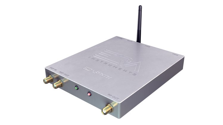
ERASynth is a portable analog signal generator that generates RF frequencies from 250 kHz to 15 GHz. The output signal is produced using an advanced multiloop PLL architecture to minimize the phase noise and spurious. This clean signal can be used as a stimulus source for RF testing, an LO source for down-conversion or up-conversion, a clock source for data converters, and as a test signal source for software defined radio (SDR).

ERASynth Features & Specifications

  • Architecture: Multiloop Integer-N PLL driven by a tunable reference. No fractional-N or integer boundary spurs
  • Frequency Range:
    • ERASynth: 10 MHz to 6 GHz
    • ERASynth+: 250 kHz to 15 GHz
  • Amplitude Range: -60 to +15 dBm
  • Phase Noise: typical phase noise @ 1 GHz output and 10 kHz offset. -120 dBc/Hz for the standard version and -125 dBc/Hz the plus version.
  • Frequency Switching Time: 100 µs
  • Reference: Ultra-low noise 100 MHz VCXO locked to a ±0.5 ppm TCXO for standard version and ±25 ppb OCXO for the plus one.
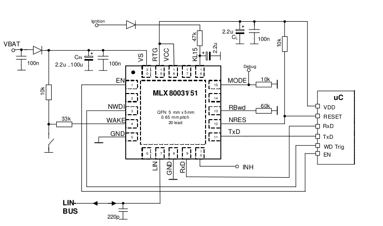
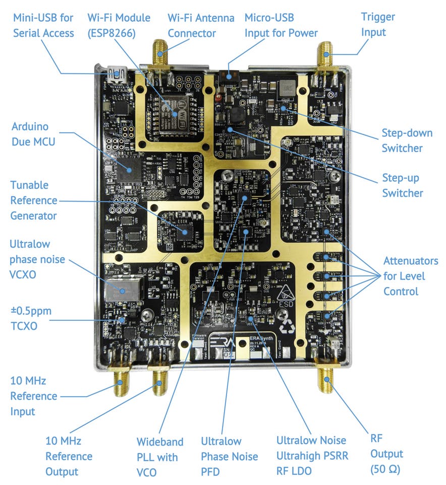
  • MCU: Arduino Due board with BGA package Atmel Microcontroller (ATSAM3X8EA-CU)
  • Interfaces:
    • Wi-Fi interface for web-based GUI access
    • Serial-USB (mini USB) for serial access
    • Micro USB for power input
    • Trigger Input (SMA) for triggered sweep
    • REF In (SMA) for external reference input
    • REF Out (SMA) for 10 MHz reference output
    • RF Out
  • Dimensions: 10 cm x 14.5 cm x 2 cm
  • Weight: < 350 g (12.5 oz)
  • Power Input: 5 to 12 V
  • Power Consumption:
    • < 6 W for ERASynth
    • < 7 W for ERASynth+
  • Enclosure: Precision-milled, nickel-plated aluminum case
  • Open Source: Schematics, embedded Arduino code, Web GUI source code, and RS-232 command set

ERASynth is only 10 x 14.5 x 2 cm sized and it is consuming less than 7 Watts. It can be powered by a cell phone power-bank. Inclusion of an on-board Wi-Fi module and an open source web GUI makes ERASynth ideal for portable applications. Also its price make it affordable by everyone including makers, students, universities, research labs, and startups.

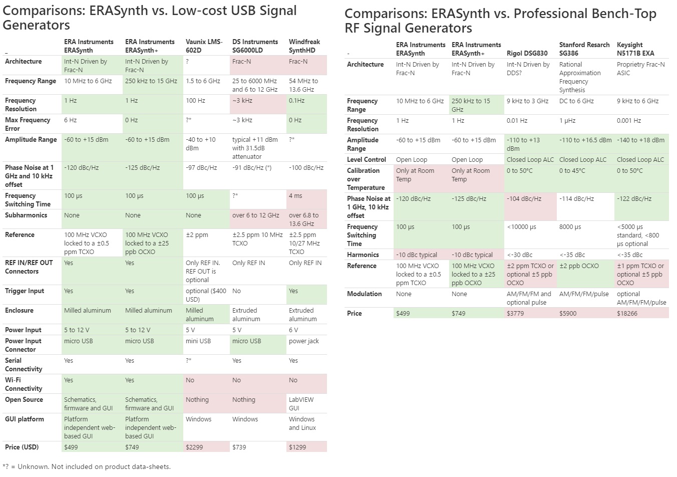
Compared with other low cost USB signal generators, ERASynth provides better features in many factors. It also delivers similar functionality of the professional RF signal generator with lower price. The tables below demonstrate the comparison.

The crowdfunding campaign on Crowd Supply will be closed by tomorrow, they raised about $35,000 of $25,000 goal. You can order your ERASynth for $500 and ERASynth+ for $750. More technical details are available on the campaign page.

Low-profile antennas can be mounted on metal surfaces

Julien Happich @ eedesignnewseurope.com discuss about a new low-profile 2.4GHz antenna that can be mounted on metal surfaces:

Antenova is shipping its first 2.4GHz antenna from its new Reflector series. The Zenon has been engineered to operate without de-tuning on metal surfaces or where the product housing is mainly metal.

The Reflector antennas are formed of two layers, one electrically isolated from the other, so as to provide RF shielding to the second layer. This means that the antenna can be placed on any kind of material and it will radiate effectively in the direction pointing away from the base material.

Low-profile antennas can be mounted on metal surfaces – [Link]

‘Tips Book for Makers’: a free download at element14

Julien Happich @ eedesignnewseurope.com presents a new book for makers from element14:

The element14 community provides support and inspiration through a combination of articles, design challenges, roadtests and the power of close to half a million global members with their combined experienced and knowledge.  This  tips book brings together hints and tips from the element14 community team, top members and friends from the Raspberry Pi Foundation, BeagleBoard.org and The Ben Heck Show to provide inspiration for makers looking to get started, or for inspiration with a project.

‘Tips Book for Makers’: a free download at element14 – [Link]

Mongoose OS Operating System for Connected Devices

Another OS for IoT applications called Mongoose OS. Like the other OS’s for IoT, Mongoose OS has some security features like:

  • Microchip ECC508A crypto chip support.
  • Supporting mbedTLS library from ARM.
  • Implementation of file system encryption and full SPI-flash encryption on ESP32.

Mongoose implements the API for: HTTP, WebSocket, MQTT and CoAP; for both client and server and with a rich API and a tiny footprint. Moreover, it integrates with Amazon AWS IoT service, Google IoT Core and Adafruit IO online service.

Talking about the SDK; Mongoose prefers to use native SDKs instead of building them from scratch by extending the original ones. The current supported microcontrollers are ESP32, ESP8266, STM32, TI CC3200. You can develop your code in C or JavaScript using mJS engine (part of Mongoose OS).

For device management and firmware building Mongoose uses a tool called mos. This tool works in Windows and Linux as a command line interface or a web UI.

In the video below there is an example of running a built-in web server using ESP WiFi module.


Last but not least, Mongoose supports the following hardware interfaces: Bitbang, GPIO, I2C, NeoPixel, SPI and UART. It can also performs remote management for the device such as: file system (list, get, put and remove), configuration, I2C, GPIO and OTA

An example of upgrading the firmware over the air (OTA) is explained in the video below :


Display Arduino analog input using LabVIEW

Zx Lee shared detailed instructions of how to display the Arduino measurements using LabVIEW:

To get started, I will explain what is actually going on in Arduino. In this project, I am using an Arduino Nano to acquire signals and send the data to PC. As mentioned earlier, two analog input channels (A0 & A1) will be used to measure input signals. To ensure an accurate measurement is performed at fixed sample rate, the Arduino is configured to wait the predefined interval before taking a measurement and send to PC serially. The concept used is similar to the BlinkWithoutDelay example in Arduino. The benefit of using this method is that there is a while loop that always checks if it has crossed the desired interval. If it is reached, it will take the measurement, else it will skip and you can make it to work on other task.

Display Arduino analog input using LabVIEW – [Link]

LIN Protocol — One Wire Protocol for Automotive Applications

With the host of protocols available in electronics interfaces, choosing a protocol is a hard job. Some protocols are designed for long distance and reliable communication applications such as RS-485. Others are used for low cost and short range communication such as I2C, and so on.

The backbone car’s network is the Controller Area Network (CAN). CAN is reliable and adopted widely in automotive industry but it’s expensive to embed CAN interface in all aspects of the car’s sub-system. As a cheap alternative, today’s protocol LIN, is designed for low cost and multi-nodes automotive networks. LIN can be used to communicate with non-critical sub-systems such as: door-lock driver and window motors. Moreover, LIN is implemented to be a one wire interface.

LIN stands for Local Interconnect Network. According to the official LIN manual, the main properties of the LIN bus are:

  • single master with multiple slaves concept.
  • low cost silicon implementation based on common UART/SCI interface hardware, an equivalent in software, or as pure state machine.
  • self synchronization without a quartz or ceramics resonator in the slave nodes.
  • deterministic signal transmission with signal propagation time computable in advance low cost single-wire implementation.
  • speed up to 20 kbit/s.
  • signal based application interaction.

The LIN topology consists of one master and several slaves. The master provides the header which consists of a break and sync pattern (0x55) followed by an identifier.

The 0x55 Synch byte helps the slaves to be synchronized with the master clock. All messages are initiated by the master with unique ID; A slave will reply according to a given message identifier.

The identifier specifies the frame type which can be one of the following:

  • Unconditional frame
  • Event triggered frame
  • Sporadic frame
  • Diagnostic frames
  • User-defined frames

The nodes are typically microcontrollers, but as LIN is designed for automotive applications in the first place, some specialized transceivers can be added to the nodes such as Melexis MLX80030 which is basically a level shifter with some add-ons like low drop voltage regulator with some protection features since the available supply voltage in cars are mostly a spiky 12v.

Note: From the schematic above you may see that the MLX80031 has split the one wire (LIN BUS) to RX and TX for the microcontroller.

When it comes to software development, there is a standard API for LIN bus (slave and master) implemented in C language.

To know more about LIN protocol please refer to Hackaday article and to the official LIN manual.

SYNTHETIC SENSORS, All-In-One Smart Home Sensor

In the era of Internet of Things, we wanted most of our home appliances to become smart. But currently, smart devices may cost much more than their offline counterparts and they often do not communicate with each other. Trying to overcome these limitations, A Ph.D student invented a way to turn entire rooms into smart with a single low-cost device called “Synthetic Sensors“.

Gierad Laput, is a Ph.D. student of computer-human interaction at Carnegie Mellon University. His research program explores novel sensing technologies for mobile and wearable computing, smart environments, and the Internet of Things.

Synthetic Sensor is a general purpose sensor that is powered directly from a wall socket and tracks ambient environmental data to monitor an entire room. It removes the need to attach additional hardware to each of home appliances.

We explore the notion of general-purpose sensing, wherein a single, highly capable sensor can indirectly monitor a large context, without direct instrumentation of objects. Further, through what we call Synthetic Sensors, we can virtualize raw sensor data into actionable feeds, whilst simultaneously mitigating immediate privacy issues. We use a series of structured, formative studies to inform the development of new sensor hardware and accompanying information architecture. We deployed our system across many months and environments, the results of which show the versatility, accuracy and potential of this approach.

The device uses machine learning to recognize the events that happen in the room, like recognizing a particular sound pattern as taking a paper towel, but it cannot monitor when the roll may need to be changed. However, by using a “second order” sensors, the devices can capture counts and send notifications of the need to replenish. This capability can be scaled to an unlimited degree giving consumers highly specific and applicable feedback.

Developers can use the recognized events as triggers for other IoT applications. For example, one could use “left faucet on” to activate a room’s left paper towel dispenser and automatically schedule a restock when its supply runs low.

The Synthetic Sensor is still in prototyping phase, you can learn more about it by visiting its website and read the research paper. Watch this video to see Synthetic Sensors in action:

EAGLE Autorouter, When & How To Use

Designing a PCB layout is a work of engineering art, includes placing components and routing them through different layers. So when you assign the same job for different engineers, each one would make it in his own way. But sometimes when working on a complex design some help may be necessary to finish the work. Autodesk EAGLE provides an autorouter feature which may assist you in many cases.

The autorouter is a useful tool that creates many routing variations for the current component placement. However, it is not a completely replacement of manually routing method. It can help you in specific situations to augment your abilities, not replace them.

When to use the autorouter?

There are three main uses of the autorouter:

  • Optimizing Placement
    While there is no rule for placing the components of the circuits, you need to evaluate your placement to ensure that you can route all parts. Autorouter completion result could be used as an indicator of your parts placement, if it was 85% or greater this means you did a good job. If not, consider pushing your parts around.
  • Discovering Bottlenecks
    You can also use the autorouter to identify bottlenecks and other critical connection points that you might have missed when placing your components. Maybe you packed a couple of ICs too close together. Your autorouter can show you where you might need to leave more space between components.
  • Getting Inspired
    When you are stuck on a section and don’t know how to route your parts, then you can call the autorouter to see how it takes care of the job, then try routing that same spot yourself with your new perspective. You might just find a strategy for your traces that you didn’t see before your autorouter gave it a try.

Using EAGLE Autorouter

Now when you find yourself stuck on some area or you feel that you need to optimize your placement or discover the bottlenecks, it is time to launch the autorouter. Follow these steps to know how it works:

  1. Open your PCB layout (.brd) file from your Autodesk EAGLE Control Panel.
  2. Select the Autorouter tool on the left-hand side of your interface to open the Autorouter Main Setup dialog.
  3. There’s quite few settings here that you can adjust:
    You’re in complete control of the autorouter setup with settings for effort, CPU threads, and routing directions.
    • Preferred direction: if you need a specific direction of the route, like vertical or horizontal, select it for each layer or you can set it to Auto. N/A means that the autorouter will not use this layer.
    • Effort: this option defines how the autorouter will work, higher effort will take more time and will provide more more routing variances.
    • Number of threads: how many threads of the CPU you want the autorouter to use? This surely will affect the time it takes to finish.
      After selecting your settings, press the Continue button.
  4. Within the Routing Variants dialog, you’ll see a list of all the routing variations the autorouter will attempt. Select the Start button to begin the autorouting process.
    Eagle Autorouting with five potential routing variations
    Autorouting on a low effort mode produced five potential routing variations that the autorouter will attempt.
  5. Once the routing is complete, select the Evaluate button, and you’ll see your completion percentage in the bottom-left corner of the interface.

If you want to unroute your board you can use the Undo (Ctrl + Z), or use the RIPUP command. Just type RIPUP ; in the command line and all of your routed traces will convert back to airwires.

To learn more about routing and autorouting you can read this tutorial, it is a part of series about Autodesk EAGLE features and how to use it. You can also view the previous tutorial about placing components.

2.7V to 38V/500 mA low noise buck-boost charge pump

Graham Prophet @ eedesignnewseurope.com discuss about Linear’s low noise buck-boost converter LTC3246, able to produce 3.3V, 5V or ADJ regulated with an input range of 2.7V to 38V :

LTC3246 is a low noise buck-boost charge pump with integrated watchdog timer capable of up to 500 mA of output current. It uses multimode switched capacitor conversion to maintain regulation over a 2.7V to 38V input voltage range and produces a regulated 3.3V, 5V, or externally adjustable (2.5V to 5V) output.

2.7V to 38V/500 mA low noise buck-boost charge pump – [Link]

PD Buddy Sink – USB Power Delivery for everyone

Clayton G. Hobbs @ hackaday.io published some details of his project, a USB power delivery board. He writes:

USB Power Delivery is a cool standard for getting lots of power—up to 100 W—from a USB Type-C port. Being an open standard for supplying enough power to charge phones, laptops, and just about anything else under the sun, USB PD is poised to greatly reduce the amount of e-waste produced worldwide from obsolete proprietary chargers. Unfortunately, like all USB standards, it’s quite complex, putting it out of reach of the average electronics hobbyist.

PD Buddy Sink – USB Power Delivery for everyone – [Link]

TOP PCB Companies