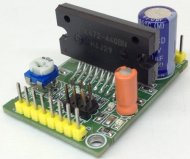
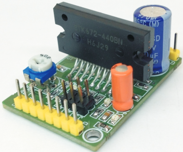
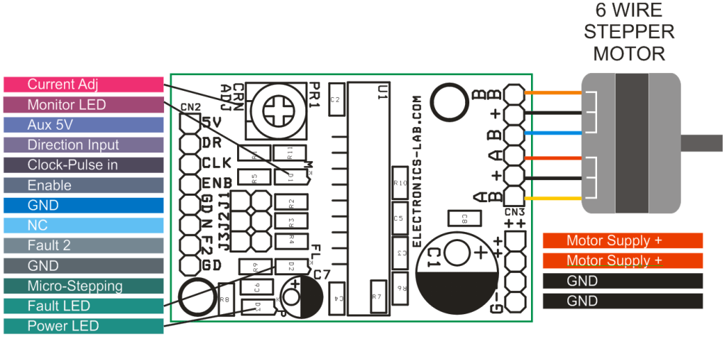
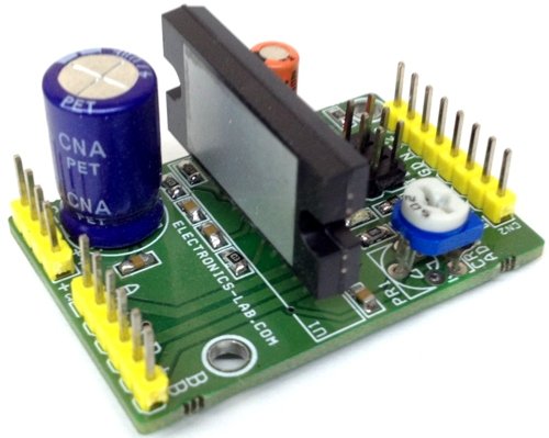
Compact Unipolar stepper motor driver can drive unipolar motor up to 3.5A and supply range 10 To 50V DC. This compact board is based on STK672-440BN IC from ON semiconductor. The STK672-440BN is a hybrid IC for use as a unipolar, 2-phase stepper motor driver with PWM current control with Micro-stepping.
Note: This Board can work with motor supply up to 36V DC, for 50V DC Supply Remove IC U2 LM317, and provide 5V Logic supply from external source. Default Enable pin is High for normal operations, pull down 0 to disable the operations, for internal Power on Reset R7 is 0E , C4 can be omit or its fine as it is.
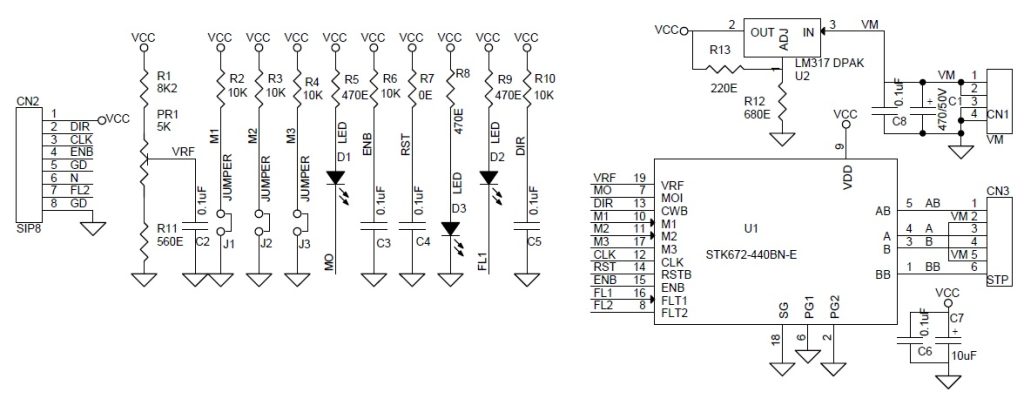
D1 LED : Excitation Monitor ( Motor Pulse Indicator)
D3 LED : Power LED
D2 LED : Fault Indicator When Over Current, Over Heat, and Motor wires open
Built-in motor terminal open detection function, (output current OFF).
Overcurrent detection function, (output current OFF).
Overheat detection function (output current OFF).
FAULT1 signal (active low) is output when any of motor terminal open, overcurrent or overheat is detected.
The FAULT2 signal is used to output the result of activation of protection circuit detection at 3 levels.
Built-in power on reset function
A micro-step sine wave-driven driver can be activated merely by inputting an external clock.
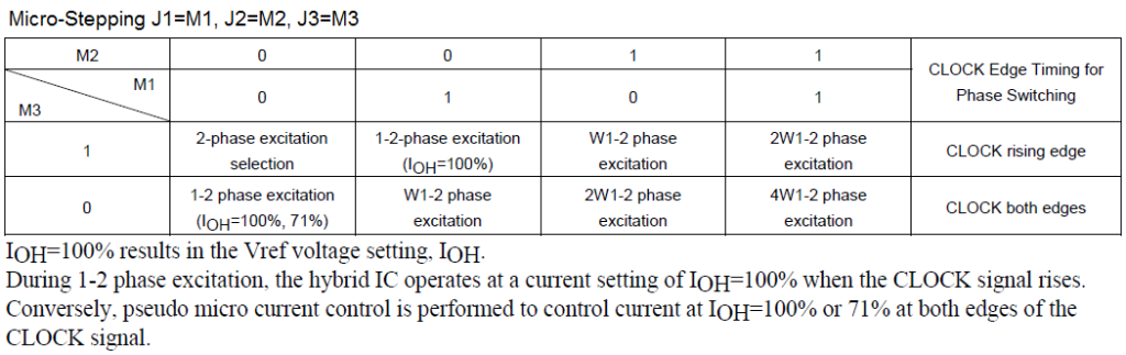
External pins can be used to select 2, 1-2 (including pseudo-micro), W1-2, 2 W1-2, or 4W1-2 excitation.
The switch timing of the 4-phase distributor can be switched by setting an external pin (MODE3) to detect either the rise or fall, or rise only, of CLOCK input.
Phase is maintained even when the excitation mode is switched.
Incorporating a current detection resistor (0.122Ω: resistor tolerance 2%),
Motor current can be set using Trimmer Potentiometer ( V Ref Range 0.2V-1.8V)
The ENABLE pin can be used to cut output current while maintaining the excitation mode
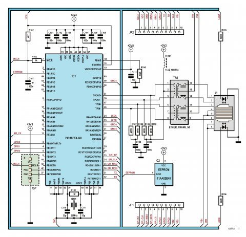
rs-online.com have published an advanced webserver project based on PIC18F67J60 microcontroller.
An Internet connection would be a valuable addition to many projects, but often designers are put off by the complexities involved. The ‘NetWorker’, which consists of a small printed circuit board, a free software library and a ready-to-use microcontroller-based web server, solves these problems and allows beginners to add Internet connectivity to their projects. More experienced users will benefit from features such as SPI communications, power over Ethernet (PoE) and more.
NetWorker – an advanced web server with a microcrontroller – [Link]
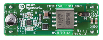
maximintegrated.com power supply experts have a reference design of a 24V to 12V flyback converter.
Maxim’s power supply experts have designed and built a series of isolated, industrial power-supply reference designs. Each of these power supplies efficiently converts 24V into useful voltage rails at a variety of power levels. Every power rail is isolated with a readily available transformer from multiple, global vendors, providing for quick, convenient transformer selection. Each design has been tested for load and line regulation, as well as efficiency and transient performance. As with all Maxim reference designs, the BOM, schematics, layout files, and Gerber files are all available. In addition, boards are available for purchase; most boards feature through-hole pins for immediate board placement and accelerated prototyping.
Isolated 24V to 12V 10W Flyback Power Supply – [Link]
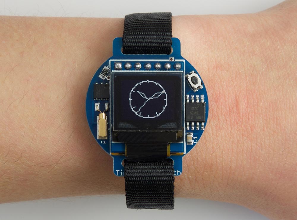
This is the third in my series of minimalist watches based on the ATtiny85. This version displays the time by drawing an analogue watch face on a miniature 64×48 OLED display. It uses a separate crystal-controlled low-power RTC chip to keep time to within a few seconds a month, and puts the processor and display to sleep when not showing the time to give a battery life of over a year.
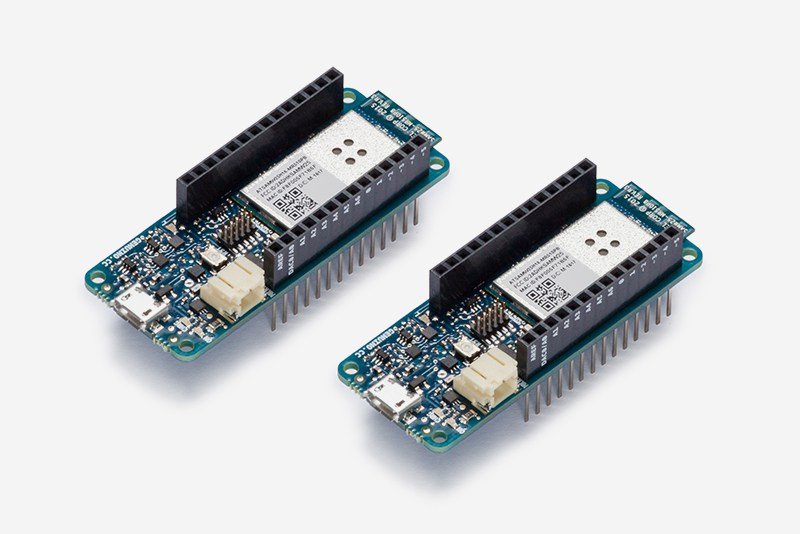
A getting start guide to program Arduino MKR1000 in Python:
The MKR1000 is described as a powerful board that combines the functionality of an Arduino Zero (already supported by Zerynth) and the connectivity of a Wi-Fi Shield, with a Cryptochip for secure communication. The design also includes a Li-Po charging circuit that allows the Arduino MKR1000 to run on battery power or external 5V, charging the Li-Po battery while running on external power.
Getting started with Python and Arduino MKR1000 for secure IoT projects – [Link]
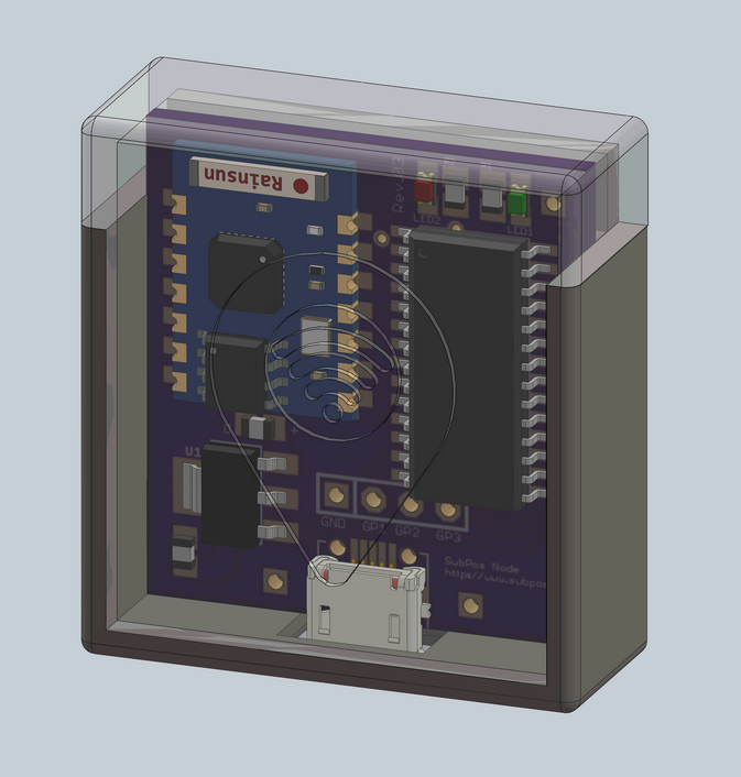
A “dataless” Wi-Fi positioning system that can be used anywhere GPS can’t. Blecky @ hackaday.io writes:
The SubPos Wi-Fi Positioning System is an indoor positioning system that can be used in various environments such as metro lines, shopping malls, carparks, art galleries or even conference centers; essentially anywhere GPS doesn’t penetrate. It could also be integrated into an array of IoT enabled devices, from access points to Wi-Fi enabled light-bulbs.
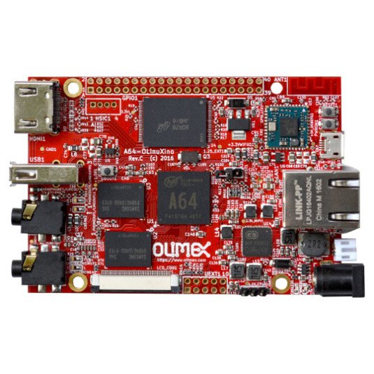
A64-OLinuXino OSHW board is released by Olimex Ltd. It’s an open source hardware board that runs Linux and Android. Entirely designed with open source software CAD tools and source files are available on github. Schematic is here.
Features
A64 Cortex-A53 64-bit SoC from Allwinner
AXP803 PMU with Lipo charger and step-up
1 or 2GB or DDR3L @672 Mhz
0 / 4 or 16GB of industrial grade eMMC
SPI Flash in SO8 package with hardware WP (not assembled)
USB-OTG and USB-HOST
HSIC connector (not assembled)
Gigabit Ethernet
BLE/WiFi module
HDMI and MIPI display connectors
microSD card
Debug console serial connector
Audio In and Out
LCD display connector
GPIO 40 pin connector (not assembled)
UEXT connector (not assembled)
5V power jack
Dimensions: 90×62.5 mm
For the moment they have three models:
1G0G with 1GB RAM, no Flash, no WiFi/BLE
1G4GW with 1GB RAM, 4GB eMMC and WiFi/BLE
2G16G-IND with 2GB RAM, 16GB eMMC with industrial grade components -40+85C
The optional connectors and SPI Flash etc may be assembled upon request for small fee. The price of the board is 50 EUR.
A64-OLinuXino board with 64-bit Cortex-A53 processor – [Link]
In July 2015, Intel and Micron Technology announced a new technology for memory and storage solutions called “3D XPoint™ technology“. It is a new category of nonvolatile memory that addresses the need for high-performance, high-endurance, and high-capacity memory and storage.
Now Intel had produced its Optane™ technology that provides an unparalleled combination of high throughput, low latency, high quality of service, and high endurance. The new technology is a special combination of 3D XPoint™ memory media, Intel Memory and Storage Controllers, Intel Interconnect IP and Intel® software.
From system acceleration and fast caching to storage and memory expansion, Intel Optane delivers a revolutionary leap forward in decreasing latency and accelerating systems for workloads demanding large capacity and fast storage.
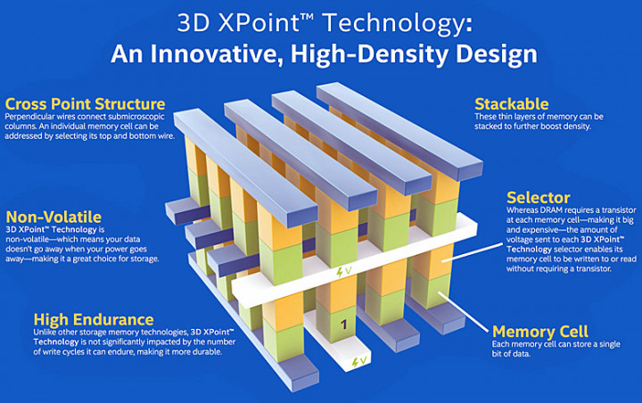
3D-Xpoint memory structure, Source: Intel Corp
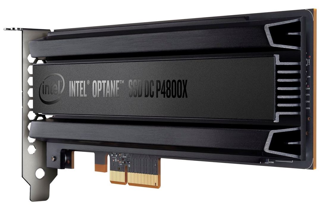
The first product with this technology is the Intel Optane SSD DC P4800X. It is a 375GB add-in card that communicates via NVMe over a four-lane PCIe 3.0 link, and it is available for $1,520 or $4.05 per GB.
Optane™ storage could be used in many sectors and domains. It will help healthcare researchers to work with larger data sets in real-time, financial institutions to speed trading, and retailers to identify fraud detection patterns more quickly. Optane™ technology can also be used at home to optimize personal computer for immersive gaming experience.
The 3D XPoint innovative, transistor-less cross point architecture creates a three-dimensional checkerboard where memory cells sit at the intersection of words lines and bit lines, allowing the cells to be addressed individually. As a result, data can be written and read in small sizes, leading to fast and efficient read/write processes.
Memory cells are written or read by varying the amount of voltage sent to each selector. This eliminates the need for transistors, increasing capacity and reducing cost. The initial technology stores 128Gb per die across two stacked memory layers. Future generations of this technology can increase the number of memory layers and/or use traditional lithographic pitch scaling to increase die capacity.
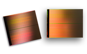
3D XPoint Technology Wafer
You can get more detailed information about 3D Xpoint and Intel Optane technologies through their official websites. You can also take a look at these two Intel P4800X reviews; Billy Tallis fromAnandTech and Paul Alcorn from Tom’s Hardware.
The LTC2063 is a single low power, zero-drift, 20kHz amplifier. The LTC2063 enables high resolution measurement at extremely low power levels. Typical supply current is 1.4μA with a maximum of 2μA. The available shutdown mode has been optimized to minimize power consumption in duty-cycled applications and features low charge loss during power-up, reducing total system power.
The LTC2063’s self-calibrating circuitry results in very low input offset (5μV max) and offset drift (0.02μV/°C). The maximum input bias current is only 20pA and does not exceed 100pA over the full specified temperature range. With its ultralow quiescent current and outstanding precision, the LTC2063 can serve as a signal chain building block in portable, energy harvesting and wireless sensor applications.