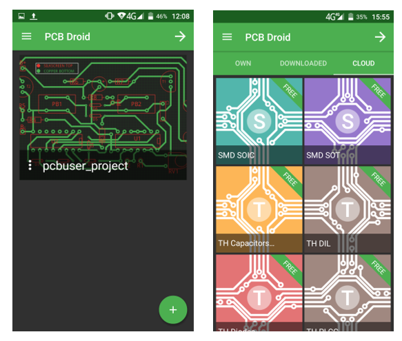
The applications available nowadays serve our everyday life well. Would it be the need of our entertainment, business life or lifestyle. However, there is one special field where we could face a serious shortcoming and it is the engineering field. I’ve come across a demand through forums specialized in electronics for a mobile application, designing printed circuits on your mobile device.
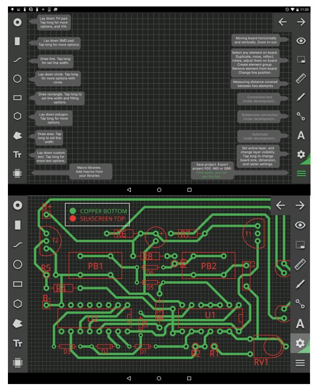
The goal was to create an application, which can be used as a designer tool for printed circuits and exporting those into different formats in an Android and Windows 10 environment. The consumption of these mobile devices is a fraction of their desktop sidekicks and an app such makes designing easier, even in your daily commute. This realization gave birth to PCB Droid application. As an electronic hobbyist as far as I’m concerned others engaged in DIY electronics usually don’t utilize the possibilities and professionalism of these programs. In practice, PC printed circuits designers are using circuit diagrams as an input. Hobbyists pretend to prefer designer programs where they can draw the marginal strips themselves and adjust them on the printed circuits. PCB Droid doesn’t require any kind of previously made circuits diagrams. The parts can be drawn onto the printed circuit by the user starting from the basic elements to the most complex components.
PCB Droid – First Mobile PCB Designer App – [Link]
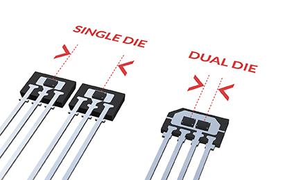
Graham Prophet @ eedesignnewseurope.com discuss about Melexis magnetic latch and switch sensors. He writes:
Melexis (Tessenderlo, Belgium) has introduced a range of new magnetic latch and switch sensors that feature two silicon dice in the same package, yielding highly reliable devices, which are aimed at automotive applications including transmission, power steering, braking and locks/latches.
Dual die, Hall effect, latch and switch sensor is accurate & redundant – [Link]
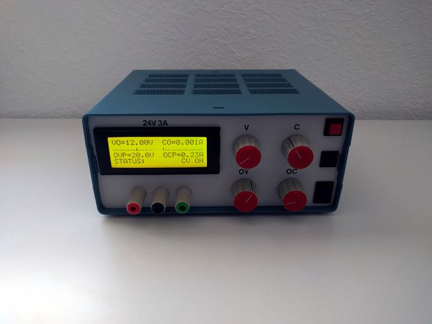
danielrp @ instructables.com build a nice power supply for his lab. He writes:
From my point of view one of the best ways to get started in electronics is to build your own laboratory power supply. In this instructable I have tried to collect all the necessary steps so that anyone can construct his own.
All the parts of the assembly are directly orderable in digikey, ebay, amazon or aliexpress except the meter circuit. I made a custom meter circuit shield for Arduino able to measure up to 36V – 4A, with a resolution of 10mV – 1mA that can be used for other projects also.
Linear Lab Power Supply with digital meter – [Link]
Sometimes it may be necessary to use a display while making a hardware project, but the size and the type of the display may vary according to the application. In a previous project, we used a 0.96″ I2C OLED display, and in this project we will have an I2C 20×4 character display.
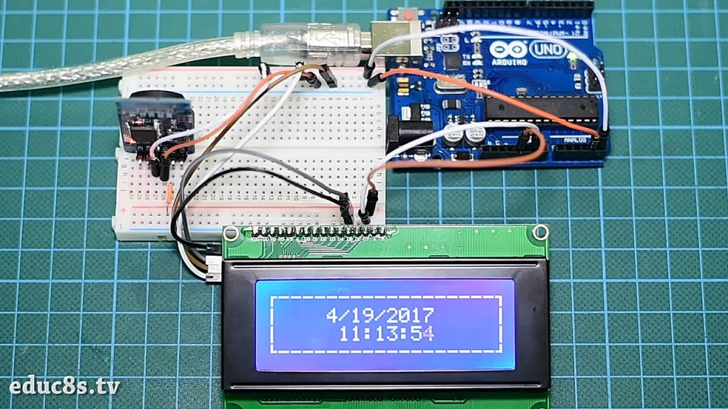
This tutorial will describe how to use 20 x 4 LCD display with Arduino to print a real-time clock and date.
Real Time Clock On 20×4 I2C LCD Display with Arduino – [Link]
Sometimes it may be necessary to use a display while making a hardware project, but the size and the type of the display may vary according to the application. In a previous project, we used a 0.96″ I2C OLED display, and in this project we will have an I2C 20×4 character display.
Project Parts
This tutorial will describe how to use 20 x 4 LCD display with Arduino to print a real-time clock and date.
20 x 4 Character LCD Display Module
This liquid crystal display has 4 lines, 20 character in each line and cannot be used to display graphics. The main feature of this display that it uses I2C interface, which means that you will need only two wires to connect with Arduino. At the back side of the screen there is a small PCB soldered in the display, this circuit is a serial LCD 20 x 4 module and it also has a small trimpot to adjust the contrast of the LCD.
Display’s backlight is blue and the text is white. It is fully compatible with Arduino and has 5V input voltage. Its I2C address could be 0x27 or 0x3F. You can get it for about $7 from Bangood store.
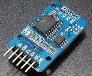
RTC maintains seconds, minutes, hours, day, date, month, and year information. Less than 31 days of the month, the end date will be automatically adjusted, including corrections for leap year. The clock operates in either the 24 hours or band / AM / PM indication of the 12-hour format. Provides two configurable alarm clock and a calendar can be set to a square wave output. Address and data are transferred serially through an I2C bidirectional bus.
This RTC module operates at input voltage range between 3.3V and 5.5V, so it can be connected with 3.3V or 5V pins. It is available on Banggood store for about $2.
Connecting the LCD with Arduino UNO
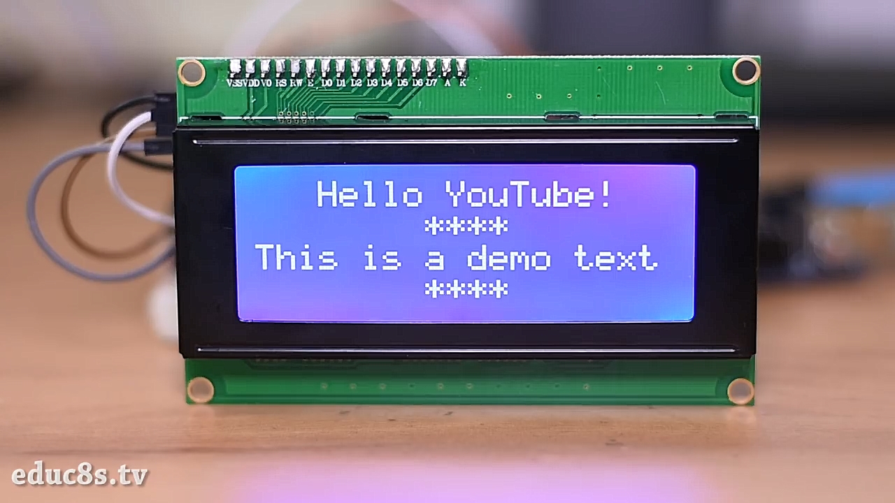
At first we will connect the LCD with Arduino to display some text and to learn how it works.
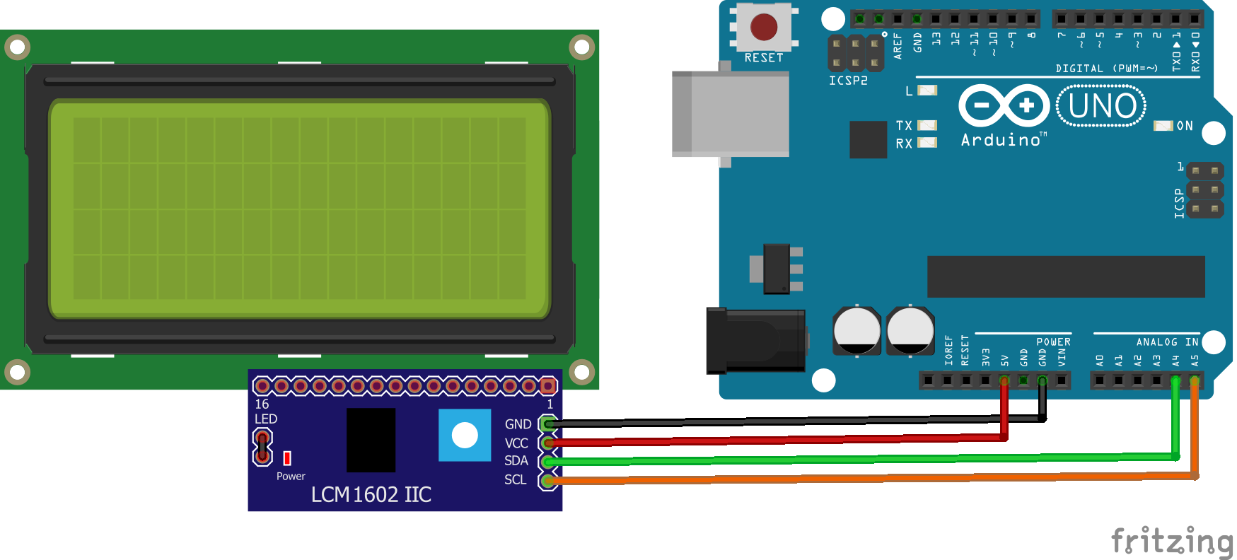
The Circuit
Connect the GND with Arduino GND, VCC with 5V pin on Arduino, SDA with A4 pin, and finally SCL with A5 pin.
The Code
First we need to download the library of the display, which includes all required functions to configure and write on the display. You can find it here.
Unzip the library and add it to the Arduino libraries folder, then run Arduino IDE and copy the following code. The first two lines are to include both of I2C and LCD libraries.
lcd.setCursor(3,0) will set the cursor of the LCD in the specified location, the first argument for the column and the second for the row starting form 0.
lcd.print(” “) will print the given text at the current cursor position, be careful that the overflowed characters will be discarded.
//Written by Nick Koumaris
//info@educ8s.tv
//educ8s.tv

#include <Wire.h>
#include <LiquidCrystal_I2C.h>

LiquidCrystal_I2C lcd(0x27, 2, 1, 0, 4, 5, 6, 7, 3, POSITIVE);  // Set the LCD I2C address

void setup()
{
  lcd.begin(20,4); // Initialize LCD
  lcd.setCursor(3,0); // Set the cursor at the 4th column and 1st row
  lcd.print("Hello YouTube!");
  lcd.setCursor(8,1);  // Set the cursor at the 9th column and 2nd row
  lcd.print("****");
  lcd.setCursor(0,2);  // Set the cursor at the 1st column and 3rd row
  lcd.print("This is a demo text");
  lcd.setCursor(8,3);  // Set the cursor at the 9th column and 4th row
  lcd.print("****");
}

void loop()
{

}
Printing Date & Time on The LCD
Now we will use the RTC module with the LCD to print current date and time, each of them in a line with a dashed border around them.
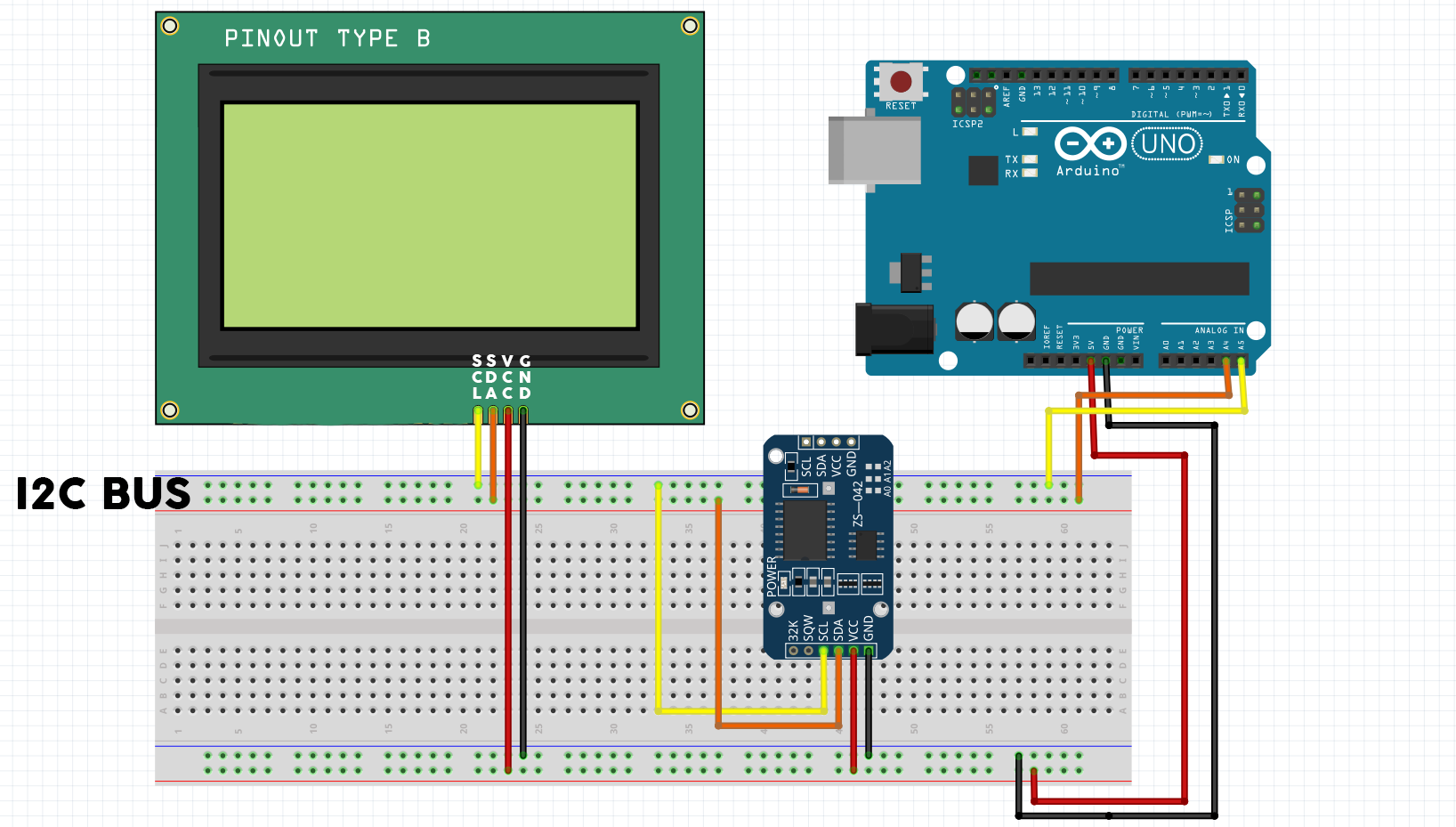
The Circuit
Here we will use a small breadboard to connect the RTC module and display with the Arduino’s I2C pins (A4 and A5). The SCL pins are connected with analog 5 pin and the SDA pins with analog 6 pin. The top rail of the breadboard used as I2C bus and the bottom one is power bus.
Connect both the display and the RTC module to 5 V and GND pins, and now the circuit is ready.
The Code
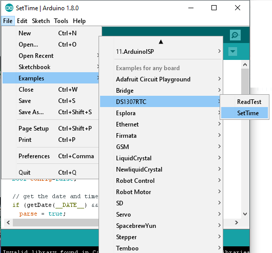
Before we start we have to download RTC library and set its time. The required library is available at github. Download it and extract it into Arduino libraries folder, then open Arduino IDE and from examples choose ‘setTime’ from DS1307 library. Finally upload it while the RTC module is connected with Arduino, and it will set its time as the computer time.
In addition to setup and loop function, we will create four other functions to organize the code. As the corners and vertical lines of the frame are special characters, we have to create them manually. So we will use a function to create them and another one to print them on the LCD.
Inside the loop function the time will be read from the real time clock module and the printed to the LCD using a custom function for each of time and date.
Now, let’s describe each part of code:
At first, we have to include the three libraries, I2C, LCD, and RTC and set the LCD address. Inside the setup function the display is initialized, then we will call createCustomCharacters() function and print them.
Each character can be 5-pixel long in width and 8-pixel in height. So to create a custom character we need to create a new byte. We need 5 characters, the vertical line and the four corners. The yellow pattern shows you how the character will be displayed on the LCD.
Inside createCustomCharacters() function, we called lcd.createChar(#, byte array) function. The LCD supports up to 8 custom characters numbered from 0 to 7. It will assign the index in the first argument to the character given by the byte array. To print this character we can use lcd.write(byte(#)) function.
Now after preparing our characters we can now print the frame.
This function is very simple, it uses lcd.setCursor(#,#) to move the cursor and lcd.print(“”) to print the given string. The function will print the top and bottom horizontal lines, then printing other custom characters.
As we discussed earlier, the loop function will get the current time and date every second and refresh them on the display. First we defined a time element “tm” which has current time data, then if the time is correct and the RTC module working fine the time and date will be printed.
We can add some instructions so, if the DS1307 is stopped or there is a circuit error,we can light a LED to indicate the problem. The loop will wait for 1 second before starting the next iteration.
void loop()
{
   tmElements_t tm;

  if (RTC.read(tm)) {
    printDate(5,1,tm);
    printTime(6,2,tm);

  } else {
    if (RTC.chipPresent()) {
      //The DS1307 is stopped. Please run the SetTime
    } else {
      //DS1307 read error! Please check the circuitry
    }
    delay(9000);
  }
  delay(1000);
}
PrintTime function uses three arguments, the column and line where it will print the time, and the time element. lcd.print(tm.Hour) will print the hour, then if the minutes and seconds are less than 10 we will add 0 to the left. And the same method is used to print the date.
Now everything is ready, upload the code to your Arduino and enjoy watching your new clock. You can find the full Arduino sketches and libraries in the attachment below.
This tutorial is made by educ8s.tv channel, and you can find the tutorial video below:
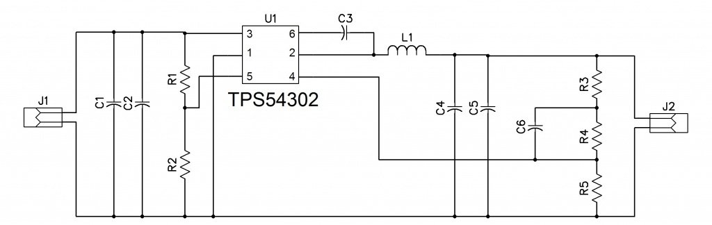
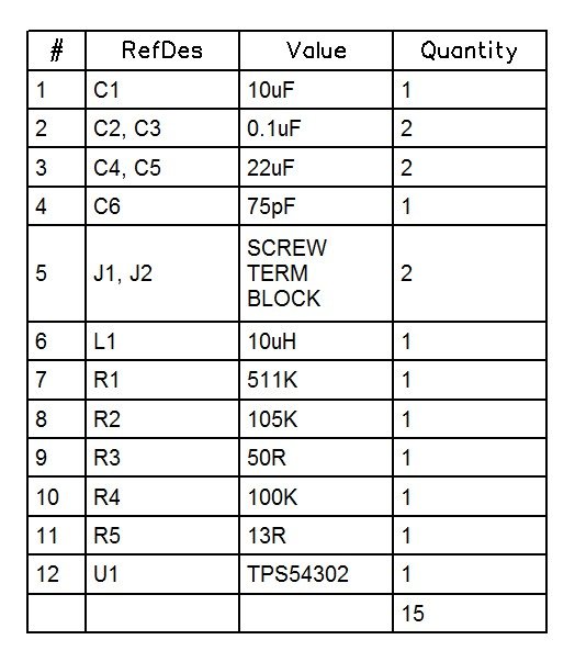
This circuit is based on TPS54302, a high efficient buck converter from Texas instrument. The input range for this circuit varies between 4.5V to 28V and it can produce an output voltage of 5V. Over voltage protection and over current protection are the two major advantages of this device.
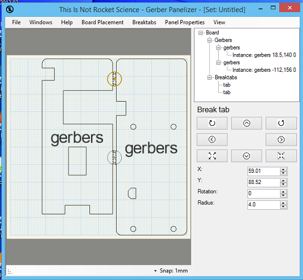
Arsenijs over at Hackaday.io explains how to panelize PCBs using GerberPanelizer on Windows. He writes:
This tutorial was done on Windows. Authors claim it could also be used on Linux by using Mono, but I haven’t tried and don’t understand a lot about Mono to see what could be done. I am switching to Linux nowadays, so I’d be very grateful to anybody that’d make instructions on how to launch it, however – and I’m sure other fellow Linux-wielding engineers will be grateful, too =)
This is the GitHub issue describing steps to launch it on Linux, half-successfully (thanks to @jlbrian7 for figuring this out
Panelization – using GerberPanelizer on Windows – [Link]
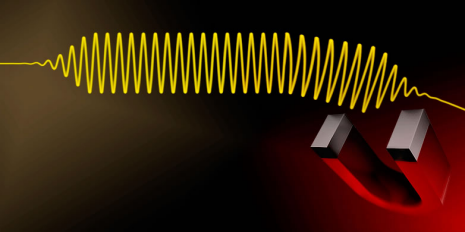
Photons became a hot research topic due to their important role in holding data across long distances. Starting from the fact that photons are insensitive to magnetic fields which concludes to their disability to process data, a group of researchers from the ETH (Eidgenössische Technische Hochschule) in Zürich are trying to make photons controlled with electric fields by giving them some electrical charge.
Visualisations: Colourbox / Montage Josef Kuster)
Photons or Polaritons?
They are using polaritons in their approach to build this artificial magnetic field. Polaritons are hybrid particles consist of coupling a photon with an electric dipole. When photons enter a material, the electrons allow themselves to be moved by the light waves or ‘polarize’, they form polaritons – coupled light and polarization waves, or excitons. Meaning that they could convert photons into polaritons. Packing excitons with them as a luggage, we can now steer polaritons indirectly by the magnetic fields.
“The combined effect of magnetic and electric fields on polaritons then leads to a gauge potential”, says Hyang-Tag Lim, a post-doctoral researcher in Imamoğlu’s laboratory.
Researches are comparing the gauge potential to a tiltable lifting platform. For example, when trying to lift a vehicle, the potential energy will change, but the vehicle won’t move. However, once we tilt the platform, a difference in height along the platform happens and the vehicle will move. Thus, a gauge potential will result in an effective magnetic field only if it varies in space.
The researchers are now looking for ways to strengthen gauge potentials. Researchers had published this researchers in the scientific journal Nature Communications, you can have a look at the research here.


 Before we start we have to download RTC library and set its time. The required library is available at