In the past, I’ve always seen small circuits of copper with no silk screen or solder mask on top of it and as a PCB designer I have always the question in my mind: What is it for? — I’ve never needed them before!
As I can find them in Arduino’s PCBs as well, I decided to open the design file and investigate more about these marks. They are called: Fiducial marks.
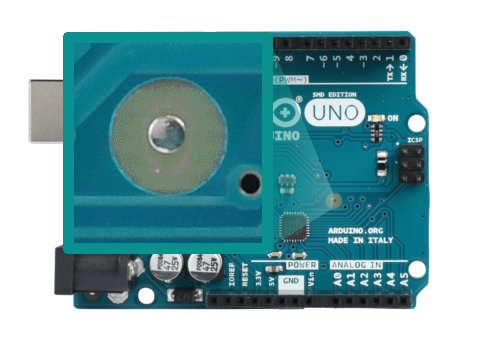
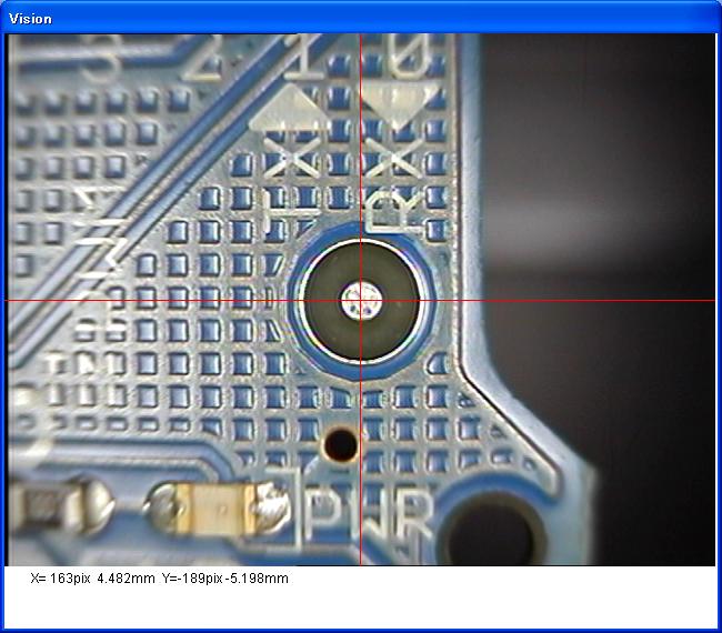
Fiducial Mark in Arduino UNO PCB. Original Image Courtesy of reichelt
Fiducial Mark is a circuit solder mask with a round bare copper in the center. The copper diameter is smaller than the solder mask. As the name may imply; these marks are used by assembling machines as points of reference, and they should be placed in any PCB side that has SMD components.
No restrict rule about how many or where theses marks should be placed. But according to the reference, it’s good to position two fiducial marks on opposite corners of the PCB, and it’s advisable to put a mark near the packages with small pitch like BGA, QFN and QFP.
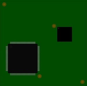
Image Courtesy of pcb-3d
When it comes to size of fiducial marks, it depends on the used assembly machine. The mark dimensions could be 3.2mm of solder mask opening diameter and 1.6mm diameter of bare copper or 2mm of solder mask opening diameter and 1mm diameter of bare copper.
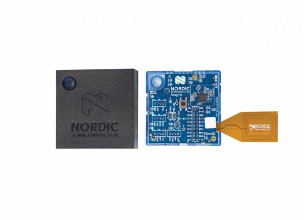
Graham Prophet discuss about Nordic Semiconductor’s nRF52832 Bluetooth low energy System-on-Chip (SoC).
Based on Nordic Semiconductor’s nRF52832 Bluetooth low energy System-on-Chip (SoC), this development kit incorporates nine different sensors plus a microphone and speaker, and enables app developers to configure, test, and demonstrate Bluetooth low energy IoT devices linked to mobile apps and Cloud platforms without needing RF firmware coding skills or development tools
Build mobile & IoT apps without hardware or firmware development – [Link]
Taking a look at what other people do in a certain aspect can give you an insight and an indicator in your own journey. Maybe IoT is one of the cutting edge technologies with rapid changes year after year, if not month after month.
About 700 developers answered Eclipse foundation IoT developer survey. The survey covers a lot of topics:
Key IoT concerns.
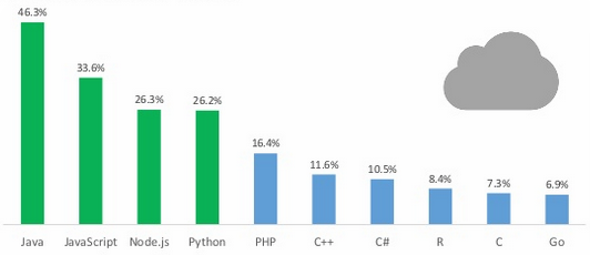
Top IoT programming languages.
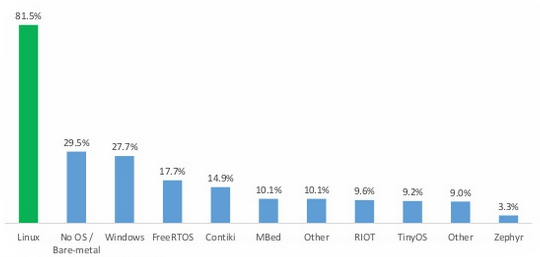
Top IoT Operating Systems and Distros.
Cloud platforms for IoT.
Growth of new connectivity technologies.
Key Trends.
According the the survey, security is the main concern for IoT developers in terms of data encryption and communication security.
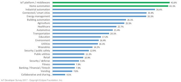
Middleware, home automation, industrial automation, smart cities, energy management, building automation, agriculture, healthcare, automotive and transportation are the top 10 in IoT industry.
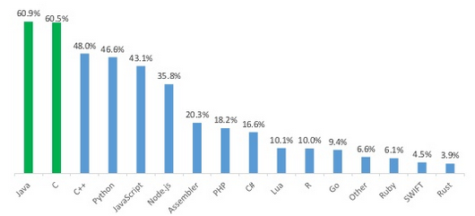
Regarding the language used by the majority of developers to build IoT solutions, C is still dominant in constrained devices followed by C++, and Java for gateway devices followed by Python.
according to the survey, constrained devices mostly have ARM Cortex M3 or M0 while Intel X86_64 and ARM Cortex v7-A are for gateway devices.
When it comes to IoT web platforms, Java, Javascript, Node.js, Python and PHP are the top five languages.
Speaking about operating systems, some of the developers use bare-metal approach; they don’t use any OS or RTOS, while most of the others use Linux. It worth to mention that the new RTOS Zephyr seems to be adopted by some developers.
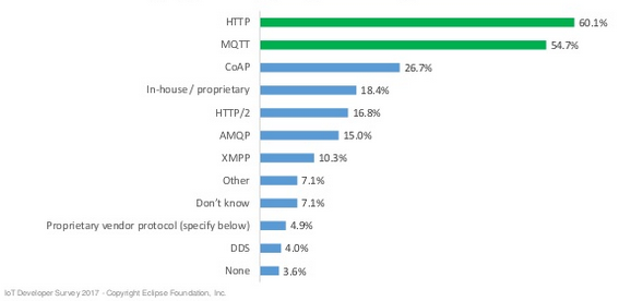
Last but not least, IoT messaging protocols is an important part of IoT development and it seems that HTTP, MQTT, CoAP, in-house (proprietary) and HTTP/2 are the top 5 messaging protocols in the survey.
The full version of the survey is available on Sildshare. Similar survey was made in 2015 and 2016.
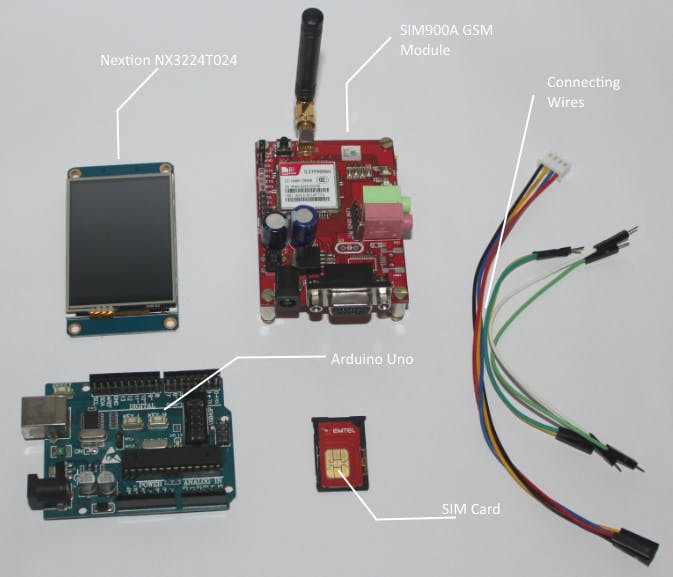
Avishek Hardin at Arduino Project Hub designed a lightweight mobile using a GSM module, an Arduino UNO, and a Nextion touch screen display. The lightweight mobile has the following features:
Make calls
Receive calls
Send SMS
Receive SMS
Delete SMS
In this project, he uses a GSM SIM900A module to establish the cellular communication. The GSM SIM900A is an all-in-one cellular module that lets you add voice, SMS, and data to embedded projects. It works on frequencies 900/1800MHz and uses the RS232 standard to communicate with MCUs. Baud rate of this module is adjustable from 9600 to 115200 through specific AT Commands.
This GSM mobile features a Nextion touch display to take input from the user and visualize the GUI. Its easy-to-use configuration software (Nextion Editor) allows you to design your own interfaces using GUI commands. All GUI data is stored in Nextion display instead of the master MCU. Thus, lots of program space in MCUs can be saved efficiently and it makes the development procedure effortless. The Nextion displays communicate with microcontrollers over UART which is supported by a wide range of MCUs.
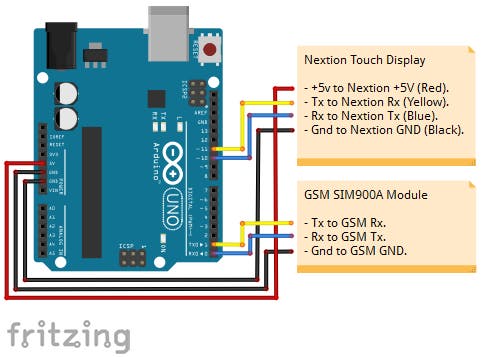
Connect the Nextion display and the GSM module with your Arduino using following instructions:
Nextion +5V to Arduino VDD_5v.
Nextion RX to Arduino pin 11
Nextion Tx to Arduino pin 10
Nextion GND to Arduino GND_0v.
GSM Rx to Arduino pin 1
GSM TX to Arduino pin 0
GSM GND to Arduino GND_0v.
Wiring Diagram of Arduino-based GSM mobile
Program The Nextion Display
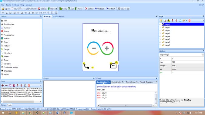
First of all, you need to design an HMI file using Nextion Editor. This editor allows you to design the interfaces using plug-and-play components like text, button, progress bar, pictures, gauge, checkbox, radio box, and much more. You can set codes and properties for each of these components later.
Design GUI using Nextion Editor
In this project, 8 different pages are used to design the GUI. All the icons used are easily available on the internet. Icons are resized and modified using an open source tool paint.net. Touch events like press and release are also covered when components are touched. More information on Nextion display commands can be found on this wiki page.
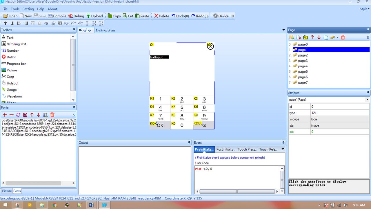
Designing dial pad using Nextion Editor
Steps To Upload
Load the .HMI file into the editor. Link to the Github repository is here.
Compile the .HMI file (just under the menu bar).
Go to File > Open build folder > Copy the .tft file > Paste into SD card. Note: make sure the SD card is formatted to FAT32.
Once copied, insert the SD card into the Nextion display and then turn the power on.
Wait for the .tft to upload.
Power off the Nextion, securely remove the SD card and then again power on the display.
Now you should see your new interfaces on the Nextion Display.
Program The Arduino
The Arduino is the brain of this project. It takes input from the Nextion display, sends commands to GSM module to create the cellular connection, and shows information on the display. This project does not use any Nextion library due to lack of documentations and difficulties to understand. Moving on without using libraries seems tough but it is really not.
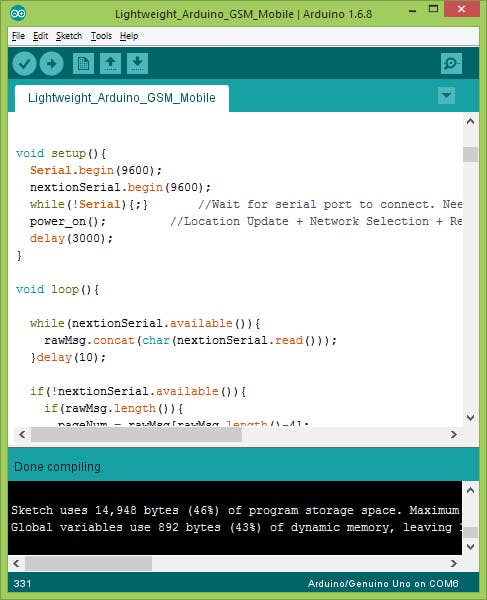
The code can be found on the Github repository. Simply download it and upload to the Arduino board using the Arduino IDE. If you are using some other board than Arduino UNO, then don’t forget to select that specific board in Arduino IDE before uploading.
Editing the Arduino sketchcompile and upload the sketch using Arduino IDE
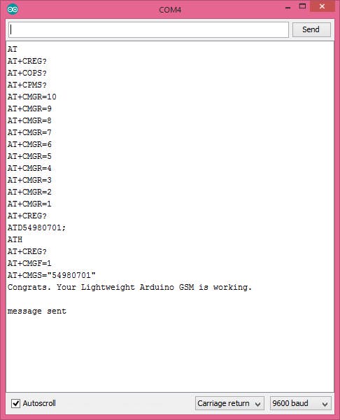
Open the Serial Monitor, you should see the AT command log for each event triggered from the Nextion Display.
Serial Monitor shows the AT command log
Important Note
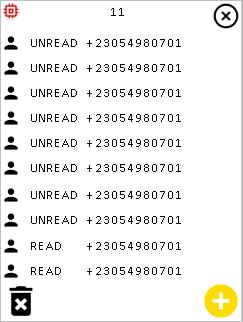
By default, the GSM module has an SMS buffer size of 20. Unfortunately, this Arduino-based mobile cannot display all the 20 messages at once on the Nextion display as it gives a buffer overflow while compiling the Nextion code. Hence, the Nextion display is programmed to show maximum 10 messages at once. If 10 or more SMS are present on the GSM buffer, the Low memory warning icon will be displayed on the Nextion display.
SMS log showing received messages on Nextion display
Video
Watch the demonstration video to understand how this Arduino-based lightweight GSMmobile works.
XOD is a new visual programming language for microcontrollers launched now. Pronounced [ksəud], this programming language idea was inspired by vvvv, a hybrid visual/textual live-programming environment for easy prototyping and development which is designed to facilitate the handling of large media environments with physical interfaces, real-time motion graphics, audio and video that can interact with many users simultaneously.
Like Code, But Better
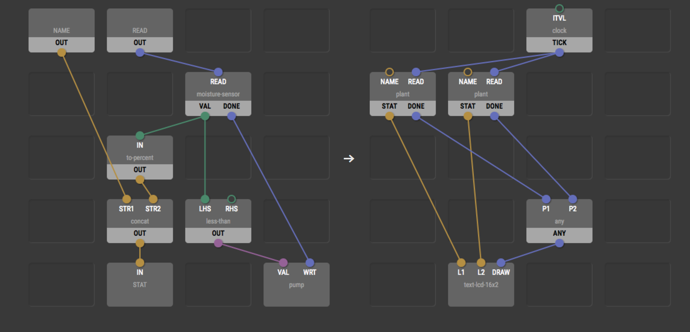
The basic unit of this language called node, a block that represents either some physical device like a sensor, motor, or relay, or some operation such as addition, comparison, or text concatenation. Each node has its inputs, outputs, and a function. Once you link the nodes together you will define a behavior. XOD will protect you from creating programs don’t compile, by making sure all nodes linked will give the behavior desired.
“If it links, it’s likely going to work“.
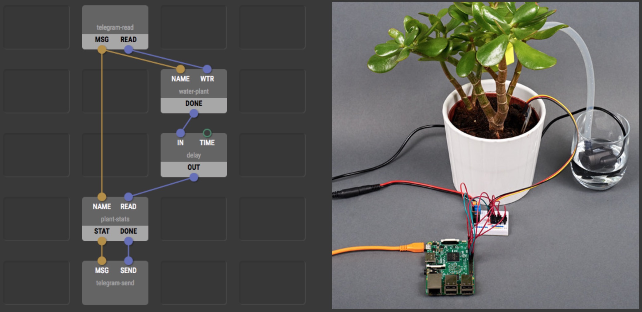
Fortunately, you won’t need Firmata or another controller PC to export the code that suits your platform. XOD will export for you the needed native code and run it directly. It is already compatible with Arduino, Raspberry Pi and other popular development boards.
XOD gives you the possibility to build your own nodes by merging some nodes together, making it simpler and faster. You can share these nodes with the community and search for trendy ones too once the platform is live.
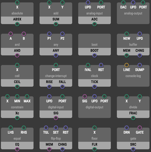
XOD includes plenty of nodes in their platform. The team believes they are good enough to start your projects just like normal programming!
27 days left for Alpha version although you can still get early access to the XOD private alpha by signing up at www.xod.io!
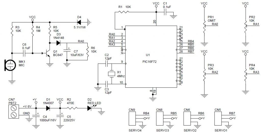
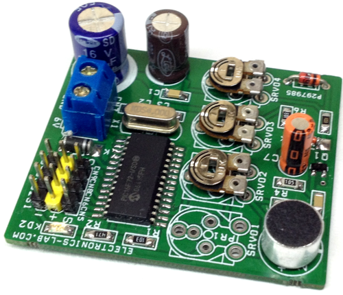
This project is designed for Animatronics and Puppeteer applications, however it can be used in other applications like sound responsive toys, robots etc. Especially this project helps to move the jaw or mouth of animatronics creature.
The project moves RC servo once receives any kind of sound. Rotation angle depends on sound level, more the sound level more the movement. Movement of the servo is proportional to sound level.
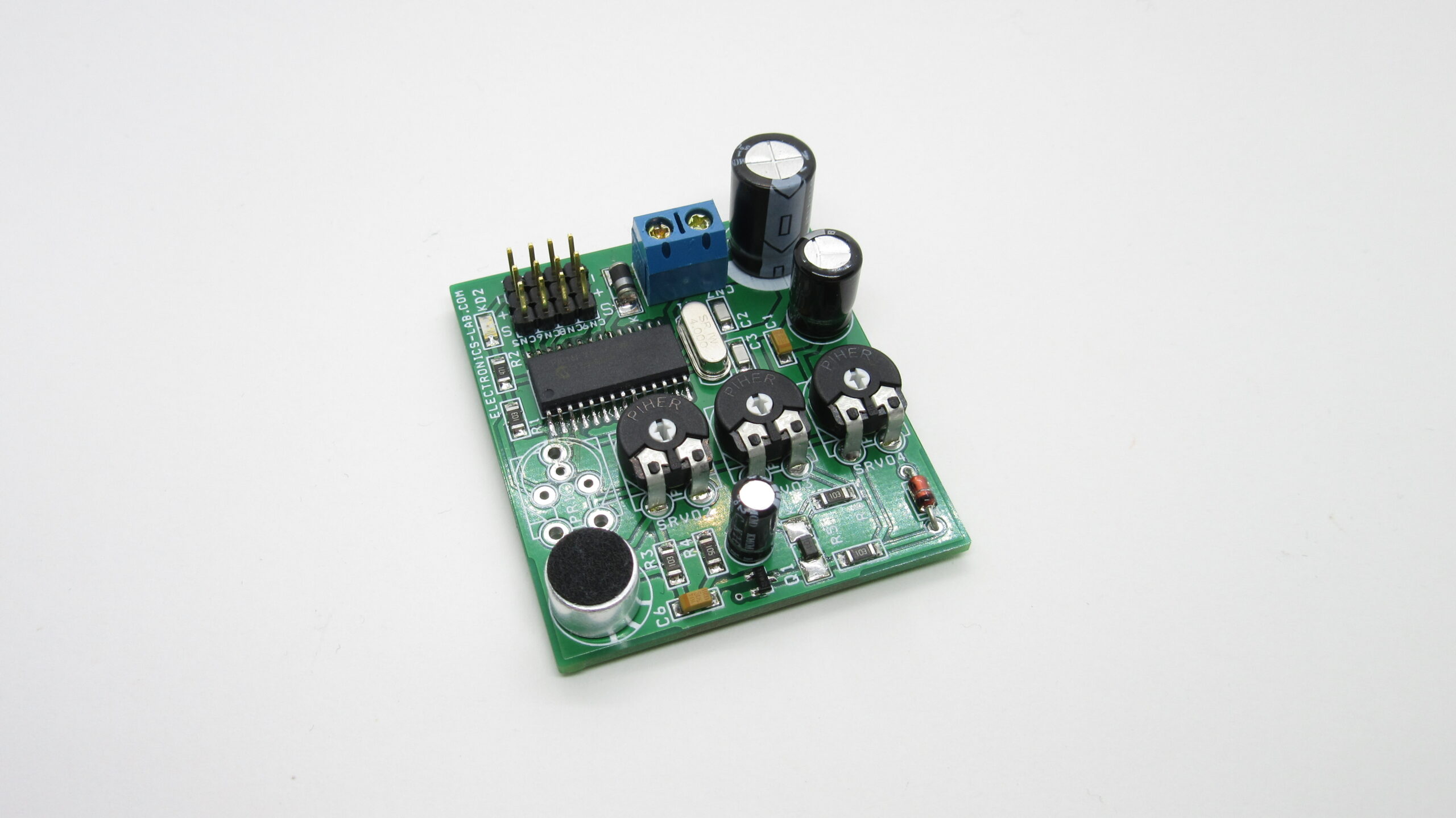
Circuit has 4 channel servo drivers, First channel is driven by sound, and rest 3 RC servos controlled by on board trimmer potentiometer, these 3 channels helps to drive other movement of animatronics figure.
Sound Received by microphone is convered to DC voltage, PIC16F72 microcontroller converts DC voltage into RC PWM signal. Circuits works with 6V DC , advisable to use battery for low jitter.
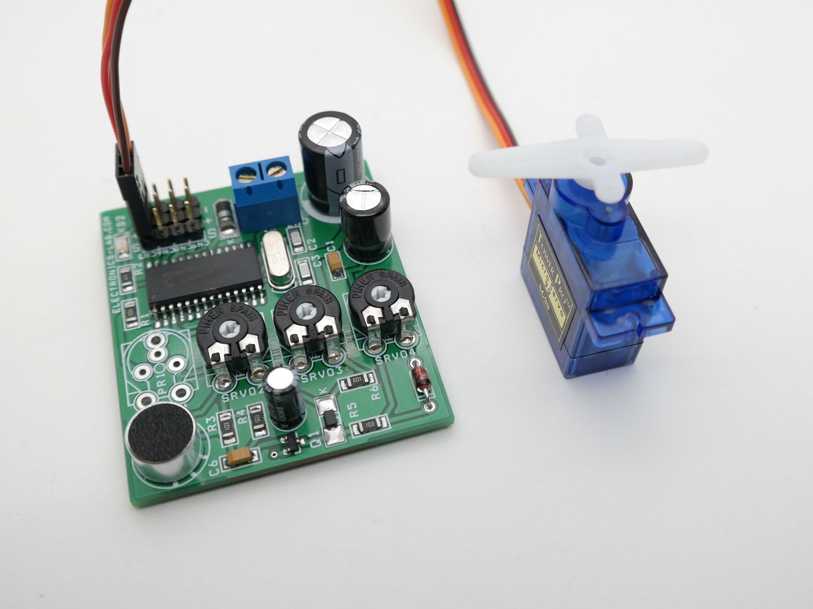
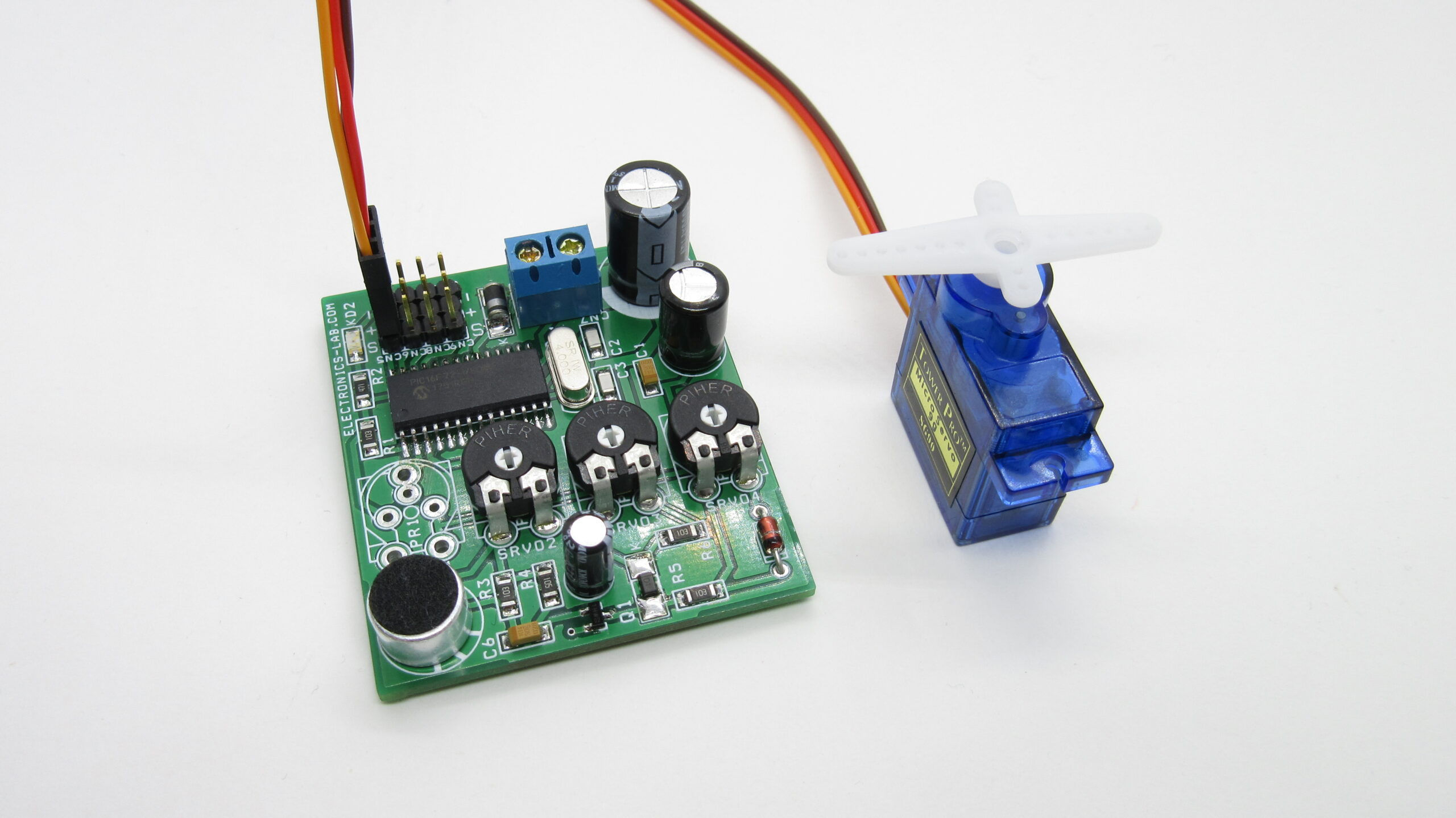
This project is designed for Animatronics and Puppeteer applications, however, it can be used in other applications like sound-responsive toys, robots, etc. Especially this project helps to move the jaw or mouth of an animatronic creature.
The project moves the RC-servo once receives any kind of sound. The rotation angle depends on the sound level, the more the sound level more the movement. The movement of the servo is proportional to the sound level.
The circuit has 4 channel servo drivers, the First channel is driven by sound, and the rest 3 RC servos are controlled by the onboard trimmer potentiometer, these 3 channels help to drive other movements of the animatronics figure.
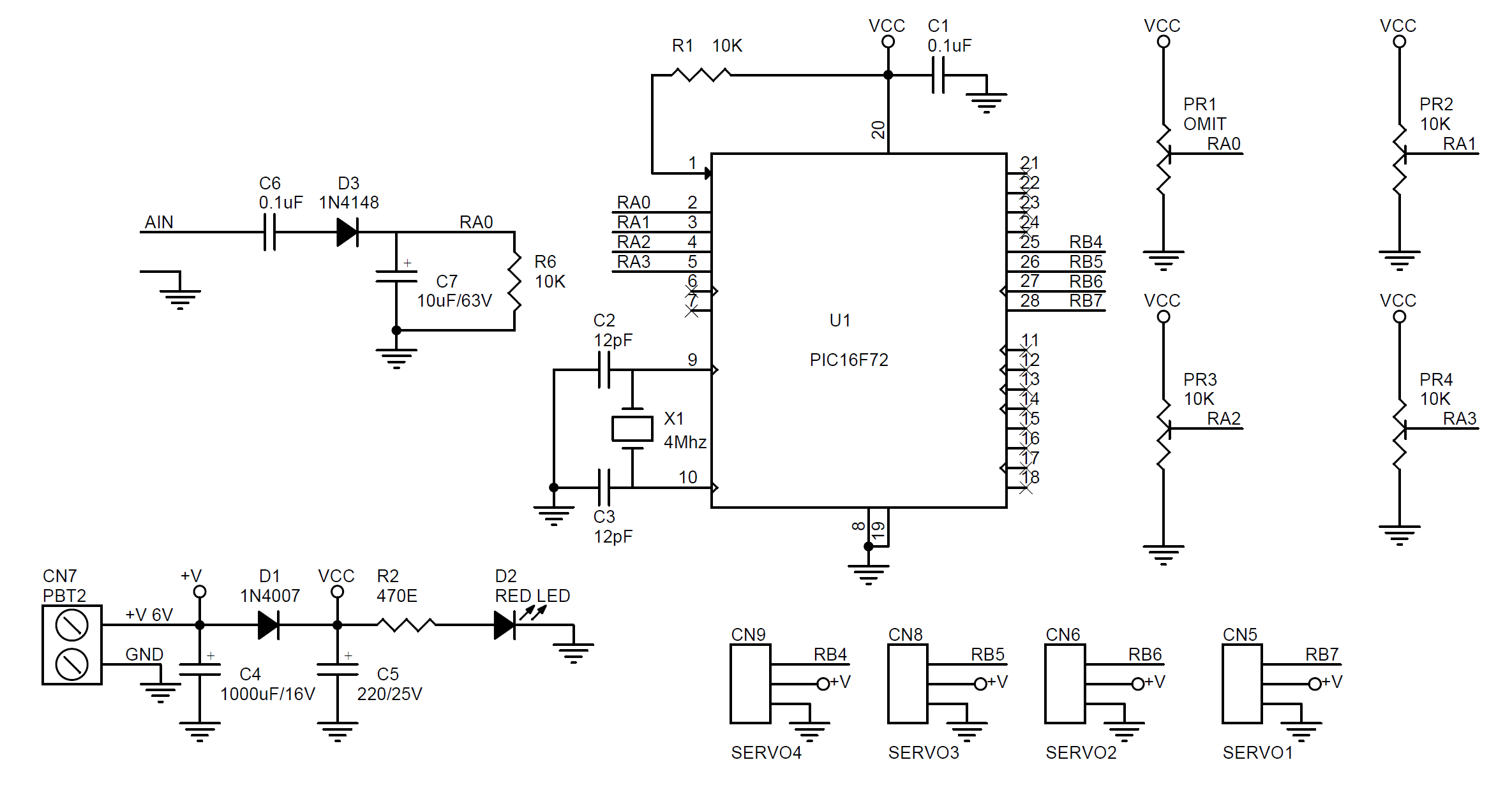
Sound Received by the microphone is converted to DC voltage, PIC16F72 microcontroller converts DC voltage into the RC PWM signal. The circuit works with 5V DC and it is advisable to use a battery for low jitter.
If you want to drive the input with a direct audio signal remove R3 (10K) and microphone and feed audio to C6, we would advise using a potentiometer (10K to 20K) before feeding audio to C6 to adjust the input level. If the audio source is from the headphones output you can remove Q1 and feed audio to the anode of D3. Refer to “Schematic with Analog Audio input” below.
As Internet of Things (IoT) devices are optimized for lower power consumption and affordability, most of them have poor computing resources. As consequence, these devices are more vulnerable to hacking attacks. The good news is there are several options for using cryptography to make it difficult for hackers to gain access to IoT devices of your smart connected home.
Cheap IoT devices that have little protection or no protection at all can be hacked to flood websites with high traffic and shut the servers down. As “things” are increasingly getting connected to the “internet”, chances are that hackers may have the water or electricity shut off, security system disabled, and even worse – they can cause loss of human life by attacking medical devices.
So, what is the solution? Well, the answer is, “Authentication and Encryption using embedded cryptography”. Now we shall discuss these methods of securing IoT devices from cyber attacks.
Secured Internet Of Things
Authentication
For the IoT, authentication works in both directions. An IoT device ensures that it is interacting with an authorized gateway and cloud service, and the cloud service (remote server), in turn, verifies it is working with an authentic IoT node. Only when both the sender and the receiver are sure that they’re dealing with “real” client/server, they proceed further and exchange confidential information. This authentication is done by using a hashing algorithm and shared secret keys to generate a tag known as a message authentication code (MAC). This MAC address is compared with a locally stored address.
Now, it’s clear that effectiveness of the authentication process depends on the strength of the MAC, and the MAC address itself depends on the strength of the hashing algorithm, the length of the key used, and whether the key is shared secretly and stored securely. The current state-of-the-art hashing algorithm for cryptographic purposes is SHA-256 with 256-bit keys. That means if the key is unknown, it will take 2^256 attempts to crack it.
The generated key must be shared over a secure channel to prohibit hackers from cracking it by sniffing the packets. The key can also be shared over an insecure channel using Diffie–Hellman key exchange method. Another important task is to store the key securely. It’s highly recommended not to store the key in the same place along with other application data.
Encryption
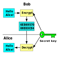
AES is the accepted encryption method to encrypt and decrypt messages using digital keys. Symmetric key cryptography uses the same key to encrypt and decrypt the message. So it’s vital to keep the key secret. Asymmetric key cryptography uses the combination of a shared, public key and a private key which is kept secret locally. Asymmetric key cryptography is more useful and safer to use over insecure channels. But, this method is too much computationally expensive. That means it requires more computing resources to deal with asymmetric key cryptography.
Symmetric key encryption
A typical IoT device may not have enough computational strength to encrypt and decrypt all the data with asymmetric key cryptography. Rather this method can be used to create a secure channel only for sharing symmetric keys that encrypt/decrypt all messages.
To make the data exchange more secure, dedicated authentication chips and cryptographic co-processors can be used. This technique makes embedded systems more power efficient and in the long run, it’s the best thing to do.
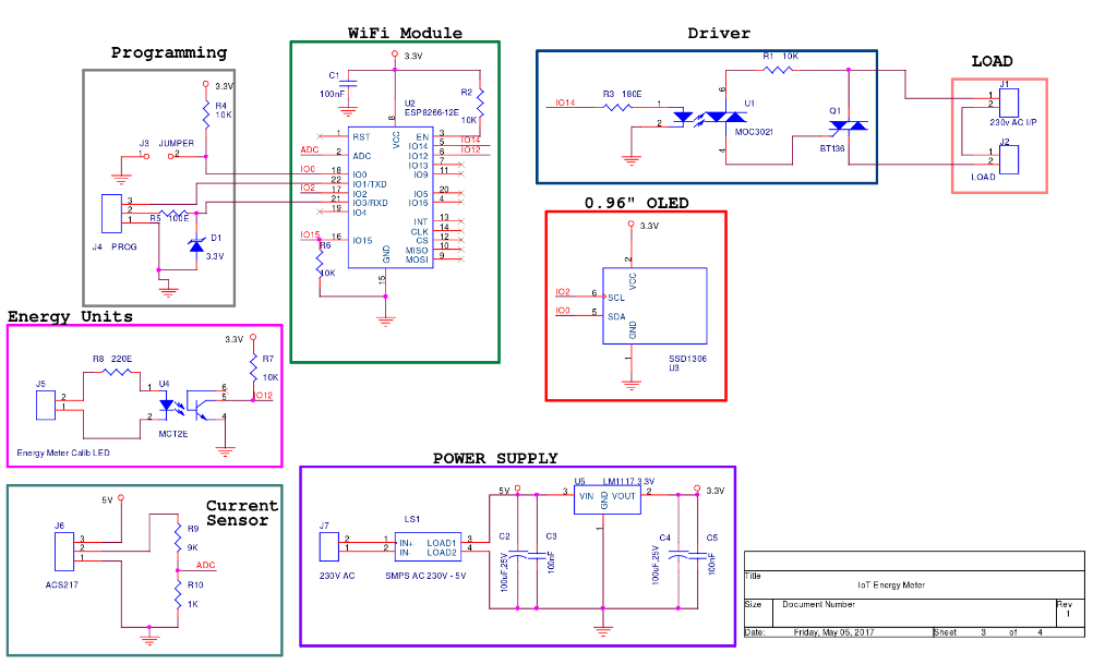
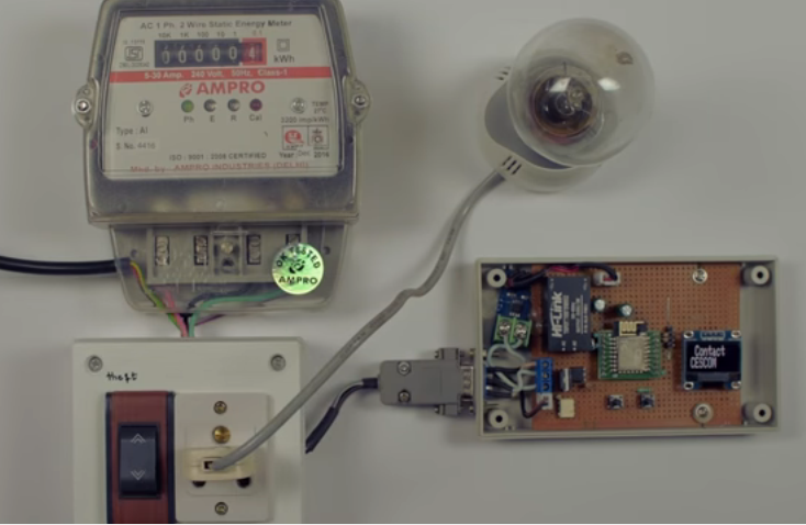
The concept behind this project is straightforward. A wire from the blinking LED of the power meter is connected to an interrupt pin from ESP8266 to count blinks (KWh) and then upload it to ThingsSpeak IoT platform to present data live online and to analyze it later.
To detect tampering, he used ACS712 AC current sensor module and connected its output (analog output) to an ADC input from ESP8266; If data from the sensor shows power consumption while no blinking form the LED is detected then a theft warning status will be issued.
The firmware, written in Arduino C, can be downloaded from Github.
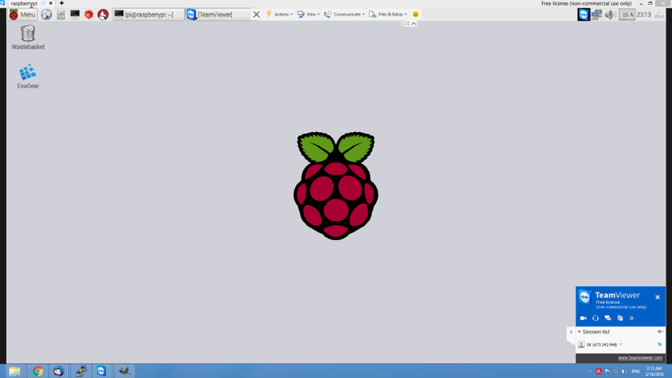
Sometimes while building a Raspberry Pi based project, it may be difficult to connect a screen, mouse and keyboard each time you want to edit something. If the Raspberry Pi is connected to a network, then running a remote desktop on it could be a good solution.
Remote Desktop Protocol (RDP) is a proprietary protocol developed by Microsoft, which provides a user with a graphical interface to connect to another computer over a network connection. In this article, you will find three different methods to run remote desktop on your Raspberry Pi.
Method 1: Using TeamViewer
TeamViewer is a proprietary computer software package for remote control, desktop sharing, online meetings, web conferencing and file transfer between computers. It is available for Microsoft Windows, Mac OS X, Linux, Chrome OS, iOS, Android, Windows RT, Windows Phone 8 and BlackBerry operating systems. It is also possible to access a machine running TeamViewer with a web browser.
ARM-based devices such as Raspberry Pi don’t have a TeamViewer version, but there is still a way to run it using ExaGear Desktop. It allows you to run Intel x86 application on ARM-based Mini PC.
Follow these steps to install and use TeamViewer on your Raspberry Pi:
Get you copy of ExaGear Desktop and install it. You can order it through the official website for $27 for Raspberry Pi 2 and $33 for Raspberry Pi 3.
Enter the guest x86 system using the following command:
$ exagearStarting the shell in the guest image /opt/exagear/images/debian-8-wine2g
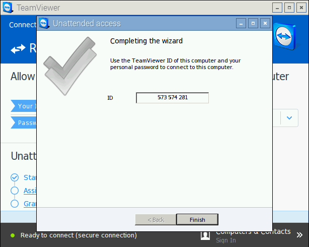
Run TeamViewer from Raspberry Pi start menu, and setup static password for remote connection. Go to connection menu, select setup unattended access and enter a name for your Raspberry and a password. Once you are finished your Raspberry Pi ID will appear.
Now download and install TeamViewer on your desktop and run it from start menu. Enter the Raspberry Pi ID in the “Partner ID” field and press connect button. A pop-up window will ask you for the password. Enter it and the remote session will open in a new window.
Method 2: Using VNC
Virtual Network Computing (VNC) is a graphical desktop sharing system that uses the Remote Frame Buffer protocol (RFB) to remotely control another computer. It transmits the keyboard and mouse events from one computer to another, relaying the graphical screen updates back in the other direction, over a network.
You can install VNC directly on your Raspberry without any additional software, follow these steps to install and prepare VNC:
Install VNC server on Raspberry using this command:
$ sudo apt-get install tightvncserver'
Start VNC server by typing “$ vncserver” on the terminal. At the first start it will ask you to enter a password which will be used to access Raspberry Pi remotely.
Get and save your Raspberry Pi IP address using this command
$ sudo ifconfig
and search for string like this (inet addr: 192.168.1.110)
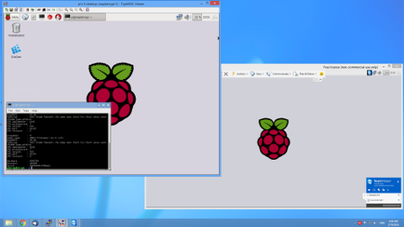
Run TightVNC Client from the start menu. In Remote Host field enter: IP address of Raspberry, colon, 1. It should be like this ‘192.168.1.110:1’ and press Connect. You are now connected to your Raspberry Pi.
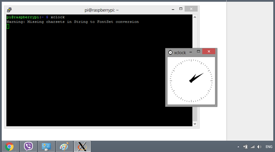
Method 3: Using ssh + X11 forwarding
Secure Shell (SSH) is a cryptographic network protocol for operating network services securely over an unsecured network. The best known example application is for remote login to computer systems by users.
X11 is the X Window System which allows you to run software on a UNIX/Linux server in a Windows-like way such that you can use your mouse to click around in it. The secure way to do this is to forward your X11 packets through your ssh connection which automatically sets your DISPLAY environment variable for you. On the configuration menu, select X11 under SSH and check “Enable X11 forwarding”.
Login to Raspberry Pi and run GUI of a program.
This tutorial is made by Eltechs, the company of ExaGear. You can visit the original post for more detailed steps and information.


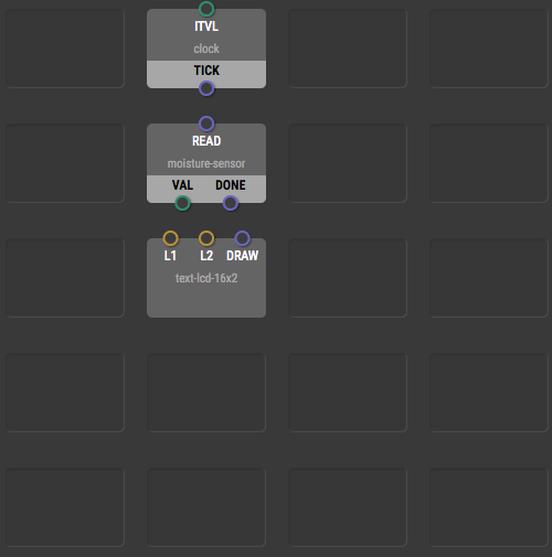 sensor, motor, or relay, or some operation such as addition, comparison, or text concatenation. Each node has its inputs, outputs, and a function. Once you link the nodes together you will define a behavior. XOD will protect you from creating programs don’t compile, by making sure all nodes linked will give the behavior desired.