Rui @ randomnerdtutorials.com tipped us with his latest tutorial. He writes:
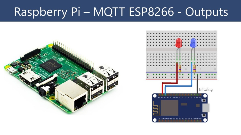
In this project you’ll create a standalone web server with a Raspberry Pi that can toggle two LEDs from an ESP8266 using MQTT protocol. You can replace those LEDs with any output (like a relay that controls a lamp).
Raspberry Pi Publishing MQTT Messages to ESP8266 – [Link]
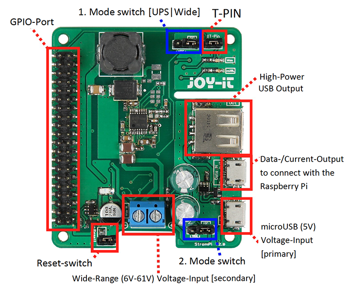
It seems evident that the Raspberry Pi and its clones have filled an enormous hidden need. The digital performance of such micro-computers is exceptional as long as they are used without any special dependence on power requirements, that is to say near an electrical outlet with power! Faced with the vagaries of the analog world, these tiny cards that fit in the palm of your hand are not as beefy as that. Their dependence on their power supply has highlighted a new need, well identified by the manufacturer JOY-iT. StromPi, their adaptable uninterruptible power supply (UPS) mini card lets you use a Raspberry Pi under conditions of unusual or unstable power, without taking up much space, and without risk of data loss in case of a power cut.
Two working modes are offered:
UPS (uninterruptible power supply), i.e. no break power
WIDE, which allows an extended range of input voltage
With the following characteristics
wide range of DC input voltage, from 6 V to 61 V in WIDE mode
5 V power input on microUSB connector
maximum USB output current of 3 A
very low standby current
(in UPS mode): 20 to 80 μA (that’s between 175 mAh and 700 mAh per year)
(in WIDE mode): 3 to 7 mA
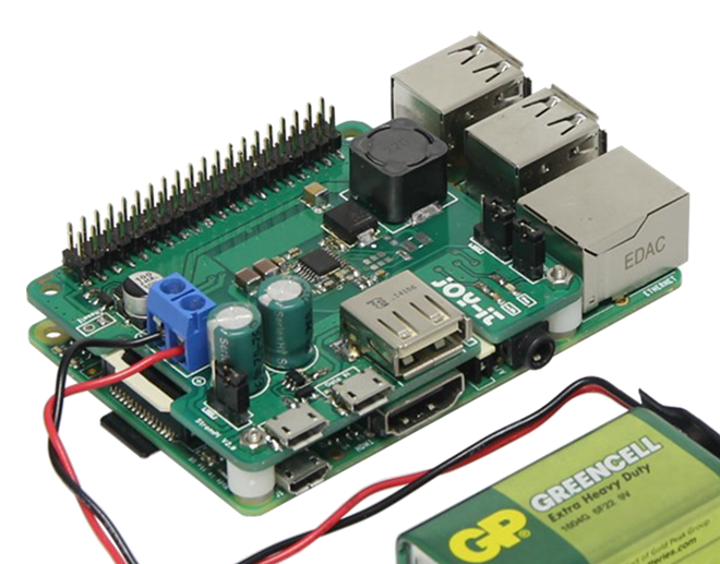
In the case of loss of power, the StromPi backup power card not only starts the process of data backup before the Pi is switched off, but it can also guarantee startup once the power is restored (this function may be deactivated with a jumper strap).
When that happens, you can even select to be informed by an email sent by the Raspberry Pi program (which you can download).
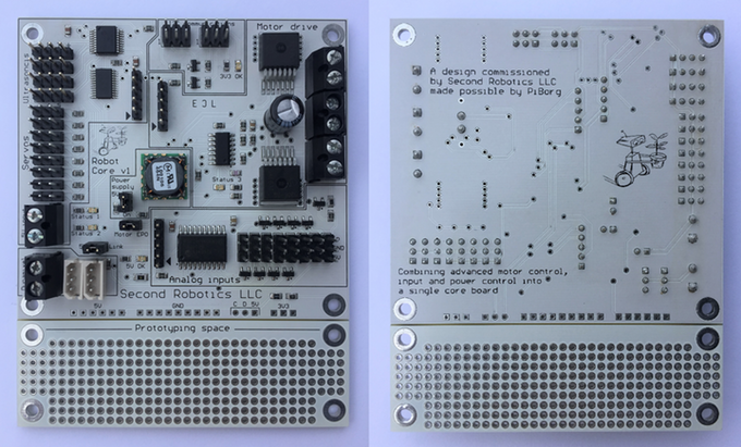
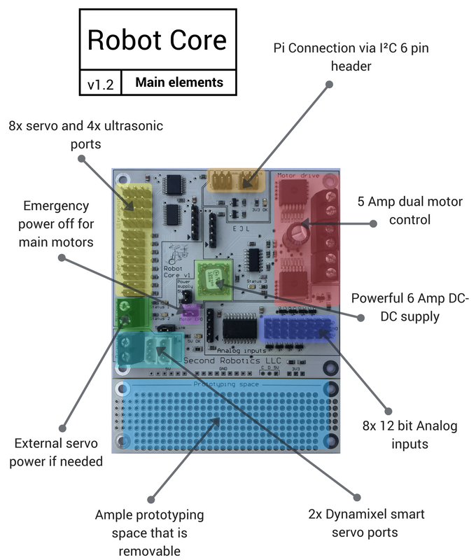
The Robot Core, which is a robot control board for the Raspberry Pi and Arduino, brings many different elements into one awesome package. It allows you to efficiently control motors, servos, and read sensor data without needing 3-4 additional boards to hookup. Several Robot Core boards can be connected together in a linear series to add even more functionality.
The Robot Core board
Robot Core uses I²C (Inter-Integrated Circuit) to communicate with Raspberry Pi. I²C is a widely used serial computer bus invented by Philips Semiconductor. It is a very easy-to-use two-wire bus that your Pi has no difficulty talking with. A built-in level shifter ensures compatibility to both 3.3 volt and 5 volts I²C buses. The Robot Core supports all Raspberry Pi boards (the past and present versions) and some Arduino boards also.
Now, let’s talk about the technical details.
Software Support:
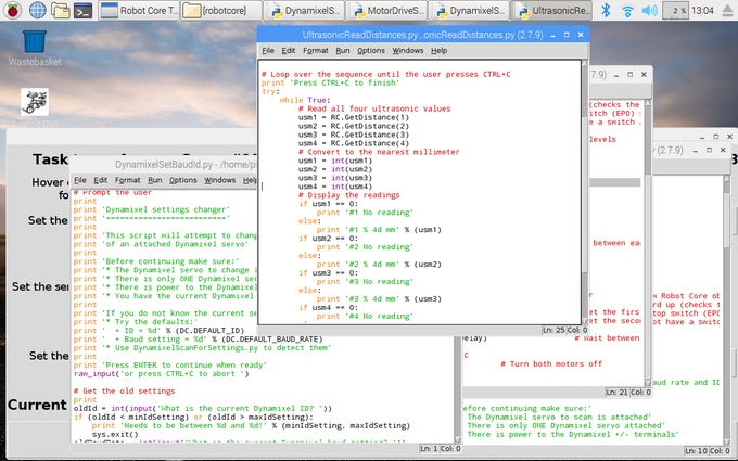
The board has software provided in the form of libraries and python example programs to get you started fast. Thanks to Second Robotics for making the software Open Source. All required resources will be available in July 2017. Currently, available links are – Drivers and Libraries, Support Documents.
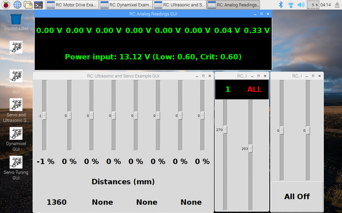
Software for The Robot CoreThe Robot Core Python Script
Motor Drive:
This board provides up to two 5 Amp continuous load DC motor outputs that can be used as a pair to drive a single stepper motor. The Robot Core’s built in safety protection prevents overheating and detects the motor failure.
Servo Control:
The Robot Core can set servos to exact position with the help of 16 bit PWM signal. It has eight ports for both analog and digital conventional servos. You can tune each servo using software-based GUI tuning method and also set their start-up positions individually.
Two ports are provided for connecting Dynamixel servos. Connecting multiple Dynamixel servos at the same time is supported. All functionalities are accessible by simple low-level commands. Many example python codes are available there to get started with Dynamixel servos.
Ultrasonic Sensors:
You can connect up to 4 ultrasonic sensors (HC-SR04) with the board. Given libraries convert measured distance into millimeter. The Robot Core board can provide filtered outputs with higher accuracy or raw outputs with greater speed, the choice is yours.
Analog Input:
Up to 8 12-bit analog inputs are supported for sensors or feedback. Each input has a range of 0-5V and the board also provides protection from exceeding the input limits. The additional analog reading for main power voltage lets you monitor supply voltage in real-time. The Robot Core has configurable warnings for low power.
Power:
The range of input voltage is 6.4v to 14v. An onboard DC-DC regulator is there for generating 5 volts, capable of providing 6 Amps current to the load. Optional separate power supply inputs for servos and for Dynamixel servos are also present.
Other Technical Information:
Clear on-board labeling. Each port and screw terminal has its pins labeled.
Prototyping space for adding more functionality. This space removable to make the board smaller.
Easy to access voltage rails.
Access to the Raspberry Pi I²C at 5V logic level.
Status LEDs are for main power voltage, DC motor status, and script controllable status.
Robot Core board details
Application Of The Robotcore Board:
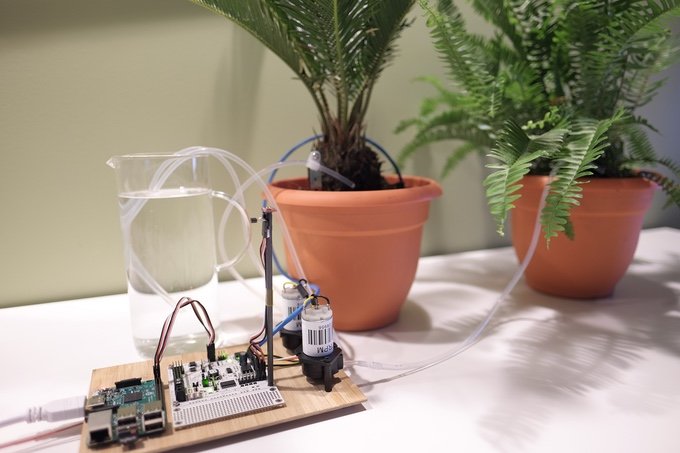
The Robot Core is an all-in-one solution for many projects. One can do pretty much any autonomous and/or robotics projects with this board. The possibilities are endless. Below are just some example projects:
A smart plant monitoring system that reads ambient light, temperature, plant moisture, and even uses two water pumps to water two different plants.
Using a single board, you can build a 2 wheeled robot with a ring of 8 analog ultrasonic sensors and a strong Dynamixel smart servo arm.
With an IMU (Inertial Measurement Unit) tied into the I²C bus, you can create a two-wheeled self-balancing robot.
Build a biped walker robot with sensors to navigate based around the board and a Pi using powerful servos or Dynamixel smart servos.
Make an automated greenhouse. Have analog sensors for light, temperature, carbon dioxide, moisture, water leaks, and also control two water pumps.
One of the talks in the “Embedded Linux Conference 2016” was about best practices to optimize C for microcontrollers. This talk deserves to be mentioned to Electronics-lab readers.
The presenter Khem Raj worked on Comcast’s (broadcasting and cable television company) reference design kit for STB, Gateway and IoT platforms.
We will cover some important points that have been suggested by the presenter:
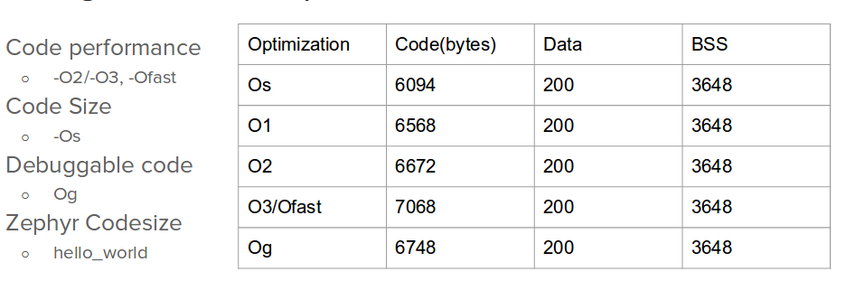
Optimization Levels
Optimization in compilers in general (GCC is the one in Khem’s case) has different levels (5 Levels: Os, O1, O2, O3 and Og). Os is for size optimization while O1, O2 and O3 are for performance.
Optimization Levels – From Khem’s slides
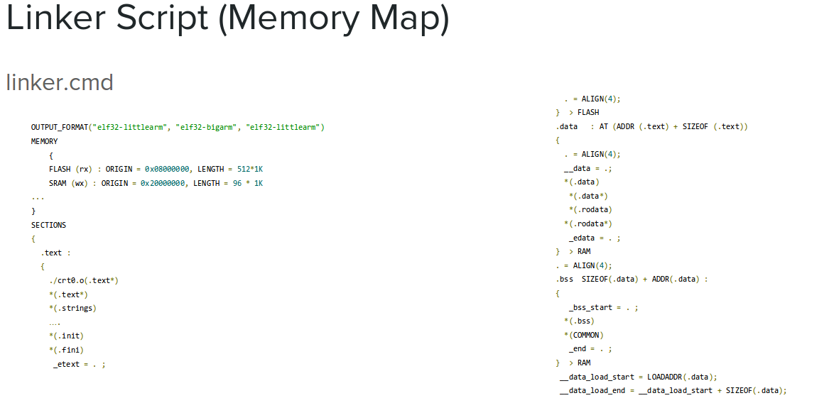
Linker
Linker which is an important tool in microcontrollers’ software toolchain, is mentioned in Khem’s talk.
Linker script is written in the linker command language and controls the memory layout of the output file (what goes where). Moreover, Linker can output a map file which is very useful when you want to track down references to symbols in the MCU memory.
Linker Script File – From Khem’s slides
Objdump
GNU GCC has a collection of binary tools; they are called (binutils); and objdump is one of them. It interleaves your assembly code with source code so you can do disassembling using it.
Variables
Talking about best practices with variables. If the concept of local, global, volatile, const and static are blurred for you, then watching this presentation will clarify them besides other important terms.
Khem also mentioned special integer types in C99; they are “fast” and “least” types. So you can allocate your variable like that:
Fixed width unsigned 8 bit integer uint8_t
Minimum width unsigned 8 bit integer uint_least8_t
Fastest minimum width unsigned 8 bit integer uint_fast8_t
To ensure portability of your code, Khem advised to use portable datatypes using uint{8,16,32,64}_t type declaration. This avoids effects of changing size of int type across different processors (compilers).
Using global and local variables is another concern. Khem advised to use local variable as much as possible. Global variable needs to be loaded from memory and stored back every time it is used. So if you use a global variable in a loop you will have multiple loading and storing operations.
Khem’s presentation has other tips about: array subscript Vs. pointer access, loop increments Vs. loop decrements and other stuff. Make sure to watch the presentation, all of it! Slides
Redux (London UK) has followed earlier announcements of its surface-wave-based haptics technology with a version specifically targeted at the smartphone, with which it aspires to “kill off smartphone micro-speakers”.
Screens become speakers, smartphones can lose micro-speakers – [Link]
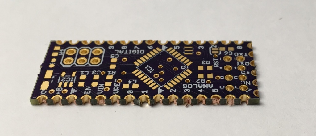
Castellations are small plated edges, typically used for making circuit boards into small pcb modules. These are often seen on wireless modules, such as the ESP8266-12E.
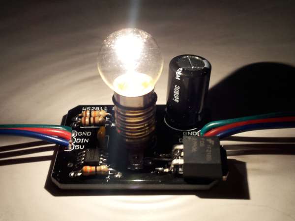
Michael wrote an article on controlling a bunch of lamps individually with WS2811 drivers and Arduino. [via]
I simply used the same technology as LED strips to allow communication between lamp modules. LED strips have RGB LEDs with an embedded driver chip which uses PWM (pulse width modulation) to control the duty cycle on the red, green, and blue LEDs. This combined LED/chip is called WS2812 or WS2812B. On older LED strips, the driver chip was not embedded into the LED itself, but was a separate chip called WS2811. These standalone driver chips are somewhat obsolete now which means they are cheap! I got 50 of them on eBay for $5.00. Since these modules use the same technology as LED strips, the same code can be used. Adafruit’s NeoPixel library is a very simple way to control LEDs, so we can control each lamp easily. The lamp is controlled by the “blue” pin on the WS2811 so that is the value to set.
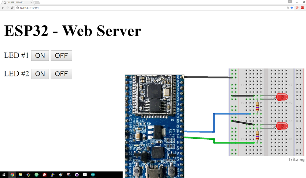
Rui @ randomnerdtutorials.com tipped us with his latest project. He writes:
In this project you’ll create a standalone web server with an ESP32 that can toggle two LEDs using the Arduino IDE programming environment. If you want to learn more about the ESP32 dev board, read my Getting Started Guide with ESP32.
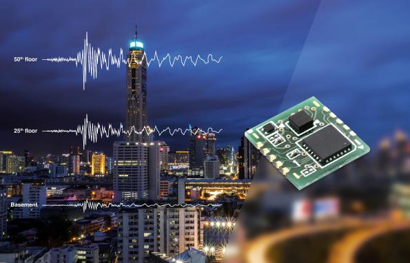
Graham Prophet @ eedesignnewseurope.com discuss about a new small seismic sensor from Omron:
Omron Electronic Components believes it has the world’s smallest class size seismic sensor, specifically designed to trigger the shutdown of potentially hazardous or easily damaged systems in the event of an earthquake.