Simple circuit indicates a low battery

@ edn.com writes:

The Design Idea in Figure 1 indicates a low-battery condition in an audio test instrument that is powered by four AA cells. As the instrument was otherwise an all-discrete design, this same approach seemed more in keeping with the spirit of the project than the use of a single-sourced integrated circuit.

Simple circuit indicates a low battery – [Link]

ESPurna-H, A Compact Open Source Hardware Wireless Power Wall Switch

Controlling your AC loads using wireless power switch is not a new concept. Several commercial products from several vendors can be found on the market such as Xiaomi’s Mi Smart Socket Plug, SAMSUNG’s SmartThings Power Outlet and Sonoff Pow WiFi Switch from ITEAD.

Using ESP8266 makes the building of a customized WiFi power switch more affordable especially if you start with Sonoff Pow WiFi Switch design and you use a special Arduino C firmware called ESPurna developed by Xose (tinkerman) which is an open source firmware for ESP8266 based wireless switches such as Sonoff POW and many others.

After Xose has built the software ــ ESPurna, he decided to build his own smart switch board to meet his special needs. ESPurna-H electronic design is very similar to Sonoff POW’s one; it uses ESP12 module as a controller and as WiFi transceiver.

ESPurna-H
ESPurna-H

AC power monitoring is done using HLW8012 IC which is also present in Sonoff POW. This IC monitors both voltage and current of the AC power, and output RMS voltage, current and active power encoded as a 50% duty cycle square wave where the frequency is proportional to the magnitude. I should mention that ESPurna supports interfacing with HLW8012. In addition AC load is enabled/disabled by using a 10A relay.

ESPurna-H uses HLK-PM01 AC-DC step-down power supply module. The 100-240 VAC input range so the board can be used anywhere in the world and the good performance made Xeos select this module.

HLK-PM01
HLK-PM01
HLK-PM01 Inside (Image Source ــ lygte-info.dk )

ESPurna-H has another option to enable/disable the relay using a capacitive touch switch using TTP223 module.

Xose designed the board with Eagle CAD and released the schematics, PCB layout and other hardware design files on Github.

Source: cnx-software

Exploring Eagle CAD ULPs #5 – Place50.ULP Place All Parts of The Board to The Position in The Schematic

Welcome to the 5th post of the “Exploring Eagle CAD ULPs” series. Each post will be about one  useful ULP in Eagle CAD.

“ULP” User Language Program is a plain text file which is written in a C­-like syntax and can be used to access the EAGLE data structures and to create a wide variety of output files. You can think about it as a plug-in for Eagle.

You can reach the posts published in this series using the following link.

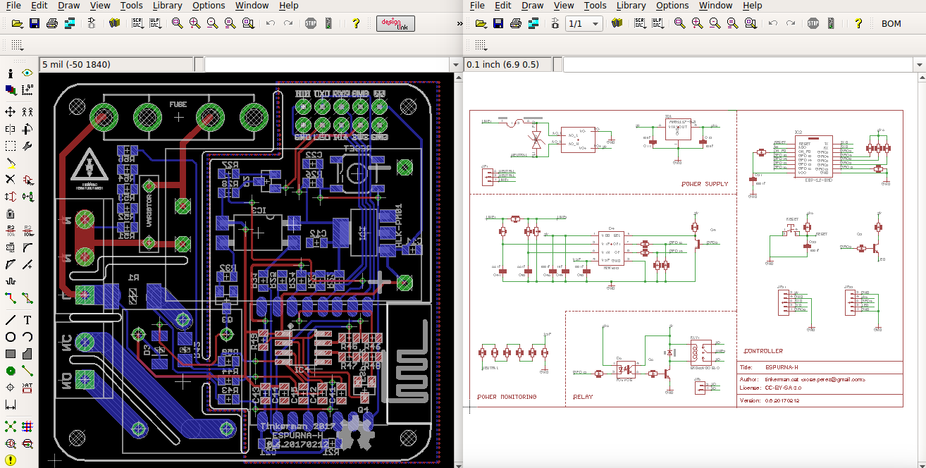
In this post, we will discuss an autoplacer ULP. Normally, Eagle CAD places parts in the board without any considerations to electrical connections, and there isn’t any built-in auto-placing tool in Eagle.

Without the help of ULPs, you will need to do this task manually by moving connected parts near to each other. However, some ULPs can solve this problem ــ manual placement is a time consuming task when the PC can help us !.

Place50 ULP has a simple and smart idea. It’s an autoplacer which places all parts of the board to the position in the schematic. To use this ULP first download it from Autodesk website to run it in schematic. Running this ULP from schematic editor will generate a script file in your home directory. Now open board editor and run the script file “place.scr”.

I made a little edit to the original ULP to make the script file be saved in the same directory of the project rather than the home directory. Download it from here.

ARM Compiler 6 With A Safety Package

Developed by ARM, the latest C/C++ compiler “ARM Compiler 6” had been announced with a safety package in a move to help developers to meet functional safety requirements.

ARM Compiler 6 is based on the modern LLVM framework and Clang technology, in close collaboration with processor and architecture projects to best utilize every new hardware feature. LLVM is a set of open-source components that allow the implementation of optimizing compiler frameworks. Clang is a compiler front end for LLVM, providing support for the C and C++ programming languages.

The ARM Compiler 6 comprises the following components:

  • ARM C, C++, and GNU assembly language compiler, armclang
  • ARM and Thumb assembler, armasm
  • ARM linker, armlink
  • ARM librarian, armar
  • ARM image conversion utility, fromelf
  • supporting libraries.

ARM Compiler enables you to build applications for the ARM family of processors from C, C++, or assembly language source. So, the ARM Compiler toolchain will be a safe option for you, whether you are a semiconductor company or you just like to know that you will be covered on your ARM projects no matter what.

“ARM Compiler is already widely used in functional safety. ARM engineering has built on that expertise and further tuned the compilation toolchain for an increasingly diverse range of safety-related applications across ARM Cortex-A, -R and -M processors.”

Tony Smith, the senior director of marketing with ARM’s Development Solutions Group.

The safety package will include the certificate and related reports from TÜV SÜD confirming that ARM Compiler 6 meets the highest tool qualification levels required by ISO26262, 61508, 62304 and EN50128. This means that you can begin developing safety-related applications with ARM Compiler 6 today, while we get the final safety artifacts ready for you.

10km ESP32 WiFi Using Directional Antenna

[Jeija] was playing with some ESP32s and in true hacker fashion, he wondered how far he could pull them apart and still get data flowing. His video answer to that question covers the Friis equation and has a lot of good examples of using the equation, decibels, and even a practical example that covers about 10km. You can see the video below.

Of course, to get that kind of range you need a directional antenna. To avoid violating regulations that control transmit power, he’s using the antenna on the receiving end. That also means he had to hack the ESP32 WiFi stack to make the device listen only on one side. The hack involves putting the device in promiscuous mode and only monitoring the signals being sent. You can find the code involved on GitHub (complete with a rickrolling application).

Of course, antennas are nothing new–look at all the Pringle can antennas we’ve seen in the past. However, the use of a long range receive-only module is interesting and we can see this technique having applications to remote drone video or telemetry and — of course — wardriving. If you don’t have a big boss antenna lying around, you might try some duct tape. If you want a more detailed refresher on decibels, we did that last month.

Source: Hackaday

MightyWatt: 70W Electronic Load for Arduino

Jakub designed and built a programmable electronic load for Arduino, the MightyWatt R3:

MightyWatt R3 is a programmable electronic load. That means you can use it for testing batteries, power supplies, fuel cells, solar cells and other sources of electrical power. You can also make a programmable power supply from a fixed-voltage power supply and MightyWatt R3 and use it for example as an intelligent battery charger.

MightyWatt: 70W Electronic Load for Arduino – [Link]

MPPT solar charger

Lukas Fässler from Soldernerd has been working on revised version of his MPPT Solar charger project:

Over the last few weeks I have been quite busy with my MPPT Solar Charger project. I’ve built up a first board and started writing firmware for it. Since the last version was not too different in terms of hardware I was able to re-use most of that code. But I hadn’t even touched on the whole USB stuff back then so there was still a lot of work to do. While the project is still far from being complete I am happy to say that I’ve made quite some progress. Most importantly, the new design seems to work well and so far I haven’t found any mistakes in the board layout. But let’s go through this step by step.

MPPT solar charger – [Link]

Raspberry Pi LCD Touchscreen Rotation

In this video, Circuit Basics walks us through the steps to change the screen rotation on an LCD touchscreen for the Raspberry Pi. Since there are separate drivers for the display and the touchscreen sensors, we need to change the orientation of both. It’s pretty simple to do, but a couple packages need to be installed first.

Raspberry Pi LCD Touchscreen Rotation [Link]

Using I2C SSD1306 OLED Display With Arduino

Sometimes it may be necessary to use a display when making a hardware project, but one confusing thing is the size of the display and the required pins to control it. This tutorial will show you how to use a small I2C OLED display with Arduino using only two wires.

The display used in this tutorial has a very small (2.7 x 2.8cm) OLED screen, that is similar to Arduino Pro Mini size, with 128 x 64 screen resolution. The OLED Driver IC is SSD1306, a single-chip CMOS OLED/PLED driver with controller for organic / polymer light emitting diode dot-matrix graphic display system. The module has only 4 pins, two of them are the supply pins, while the others are SCL and SDA, I2C protocol pins, which will be used to control the display.

Using I2C SSD1306 OLED Display With Arduino – [Link]

$10 Orange Pi 2G-IoT Competing With Pi Zero W

A new competitor to Raspberry Pi Zero W is just out! A new single-board computer by Orange Pi that is now available at AliExpress is competing against Pi Zero W, the Orange Pi 2G-IoT. Using this powerful SoC you can build a computer, a wireless server, games, musics and sounds, a speaker with Android, Scratch and a lot of other options since Pi 2G-IoT is open source.

The Orange Pi 2G-IoT has ARM Cortex-A5 32bit clocked at 1GHz with 256MB DDR2 RAM, 500 MB of on-board NAND storage to go along with an SD card slot for larger storage. It also has a CSI camera connector, WiFi, Bluetooth, an FM Radio and GSM/GPRS with a sim card slot on the bottom. It is pin compatible with Raspberry Pi’s almost standardized GPIO layout.

This $10 board is impressive especially the addition of GSM/GPRS, but it is not promised to kill other competitors in sales, even though it is a powerful little computer. Since the community of Raspberry Pi product is much more larger and more supportive, Orange Pi fails in engaging its audience with the products it makes.

Unfortunately, Orange Pi website is not updated yet to include its newest product. However if you are interested in getting one for yourself right now, head over to AliExpress to get your 2G-IoT for only $9.90 and to know more details.

Via Hackaday

TOP PCB Companies