Sometimes it may be necessary to use a display when making a hardware project, but one confusing thing is the size of the display and the required pins to control it. This tutorial will show you how to use a small I2C OLED display with Arduino using only two wires.
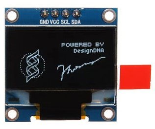
The display used in this tutorial has a very small (2.7 x 2.8cm) OLED screen, that is similar to Arduino Pro Mini size, with 128 x 64 screen resolution. The OLED Driver IC is SSD1306, a single-chip CMOS OLED/PLED driver with controller for organic / polymer light emitting diode dot-matrix graphic display system. The module has only 4 pins, two of them are the supply pins, while the others are SCL and SDA, I2C protocol pins, which will be used to control the display.
Using I2C SSD1306 OLED Display With Arduino – [Link]
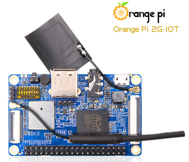
A new competitor to Raspberry Pi Zero W is just out! A new single-board computer by Orange Pi that is now available at AliExpress is competing against Pi Zero W, the Orange Pi 2G-IoT. Using this powerful SoC you can build a computer, a wireless server, games, musics and sounds, a speaker with Android, Scratch and a lot of other options since Pi 2G-IoT is open source.
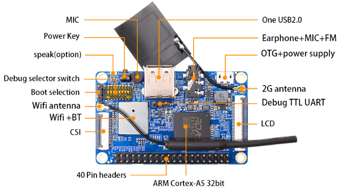
The Orange Pi 2G-IoT has ARM Cortex-A5 32bit clocked at 1GHz with 256MB DDR2 RAM, 500 MB of on-board NAND storage to go along with an SD card slot for larger storage. It also has a CSI camera connector, WiFi, Bluetooth, an FM Radio and GSM/GPRS with a sim card slot on the bottom. It is pin compatible with Raspberry Pi’s almost standardized GPIO layout.
This $10 board is impressive especially the addition of GSM/GPRS, but it is not promised to kill other competitors in sales, even though it is a powerful little computer. Since the community of Raspberry Pi product is much more larger and more supportive, Orange Pi fails in engaging its audience with the products it makes.
Unfortunately, Orange Pi website is not updated yet to include its newest product. However if you are interested in getting one for yourself right now, head over to AliExpress to get your 2G-IoT for only $9.90 and to know more details.
Sometimes it may be necessary to use a display when making a hardware project, but one confusing thing is the size of the display and the required pins to control it. This tutorial will show you how to use a small I2C OLED display with Arduino using only two wires.
Geekcreit 0.96 Inch I2C OLED Display Module
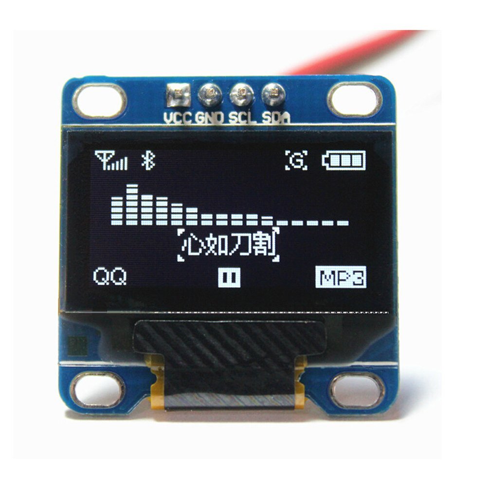
The display used in this tutorial has a very small (2.7 x 2.8cm) OLED screen, that is similar to Arduino Pro Mini size, with 128 x 64 screen resolution. The OLED Driver IC is SSD1306, a single-chip CMOS OLED/PLED driver with controller for organic / polymer light emitting diode dot-matrix graphic display system. The module has only 4 pins, two of them are the supply pins, while the others are SCL and SDA, I2C protocol pins, which will be used to control the display.
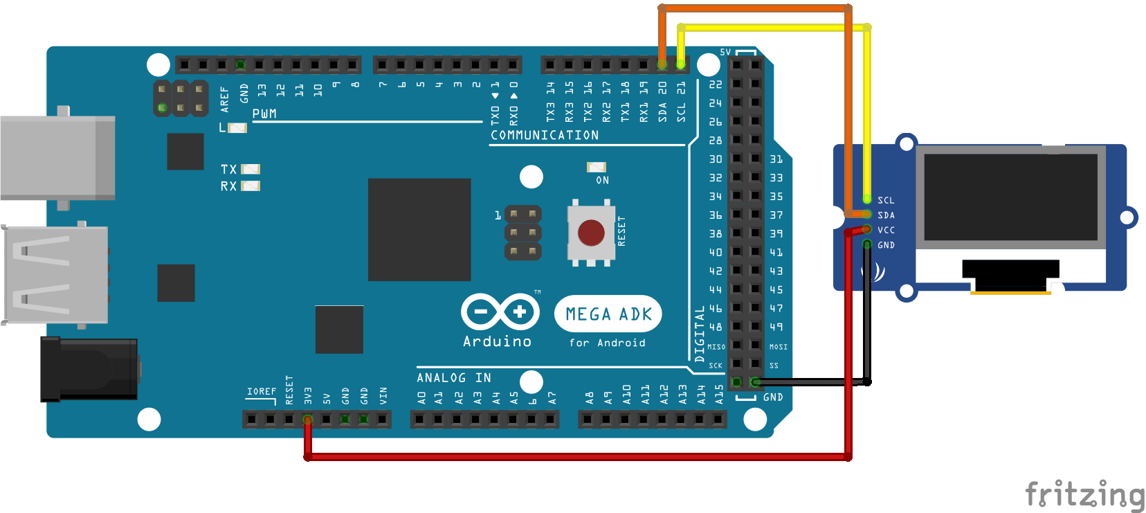
This OLED display module is full compatible with Arduino and has an input voltage range between 3.3V and 6V and it need less than 10 mA current, so it can be connected with 3.3V or 5V pins. It is available on Banggood store for about $5.5.
The circuit is very simple. First, connect the GND with Arduino GND, VCC with 3.3V or 5V on Arduino, SCL with SCL, and finally SDA with SDA pin. Upload the code and power on the Arduino.
I2C Protocol
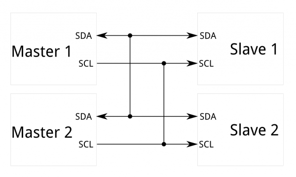
The Inter-integrated Circuit (I2C) Protocol is a protocol intended to allow multiple slave digital integrated circuits to communicate with one or more master chips. It is only intended for short distance communications within a single device, and it only requires two signal wires to exchange information.
Each I2C bus consists of two signals: SCL and SDA. SCL is the clock signal, and SDA is the data signal. The clock signal is always generated by the current bus master. Messages are broken up into two types of frame: an address frame, where the master indicates the slave to which the message is being sent, and one or more data frames, which are 8-bit data messages passed from master to slave or vice versa. Data is placed on the SDA line after SCL goes low, and is sampled after the SCL line goes high.
The Code
First of all you need to download two libraries:
Adafruit GFX library, this is the core graphics library, providing a common set of graphics primitives (points, lines, circles, etc.). It needs to be paired with a hardware-specific library.
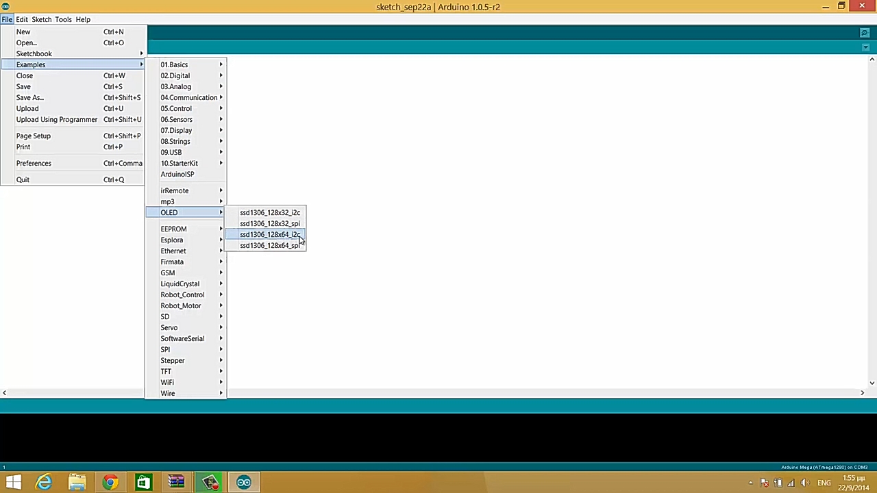
Unzip the two libraries and add them to the Arduino libraries folder, then run Arduino IDE and open the I2C exapmle from OLED library.
The only change you have to do is to change the I2C address of the display. Go to the setup function, and change the value on the display.begin function call from 0x3D to 0x3C. This is required because the 0x3D is the address of Adafruit OLED display, while the 0x3C is the address of the OLED display from Banggood.
After uploading the code to the Arduino, the screen will light up and start displaying lines, triangles, circles, and texts. You can use the function in the code to draw what you need.
This tutorial is made by educ8s.tv channel, and you can find the tutorial video below:
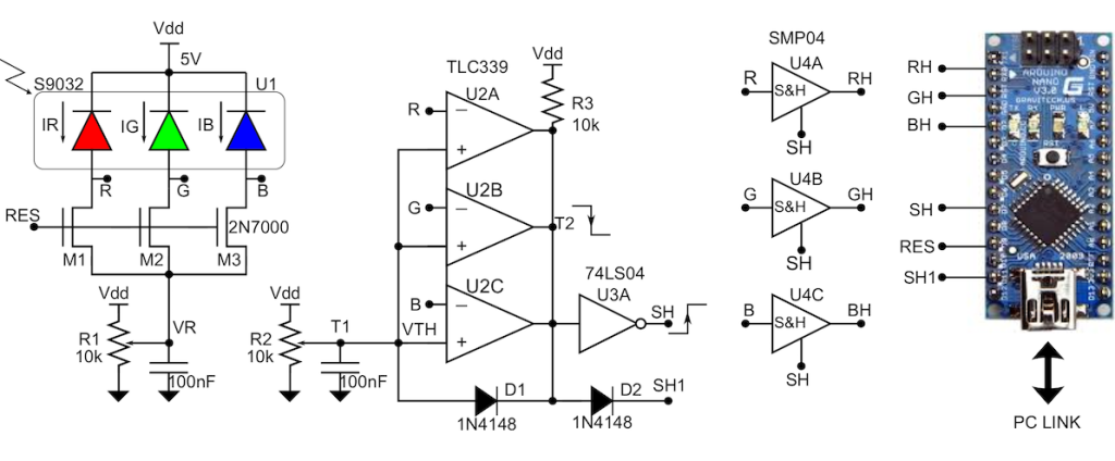
The Design Idea in Figure 1 is a color detector capable of generating an RGB triplet over a high dynamic range, a useful attribute for machine vision applications. The circuit implements auto-exposure control to achieve this. Thus, RGB values for a subject are invariant over a range of light intensity.
Color sensor achieves high dynamic range with auto exposure – [Link]
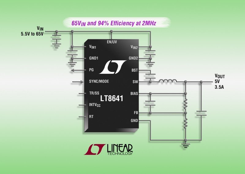
The LT8641 is a monolithic, constant frequency, current mode synchronous (external schottky diode is not necessary) step-down switching regulator. Its 3V to 65V input voltage range makes it ideal for 12V or 24V automotive and industrial applications. It delivers up to 3.5A of continuous output current and peak loads of 5A. Output voltages can be set in 0.81 to 64V range. [via]
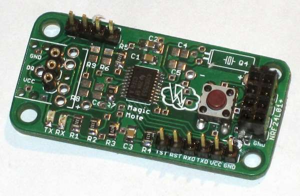
This is my first time designing a PCB for MSP430. I really like the NRF24L01+ booster pack but I would like something smaller to use for remote temperature sensors. With that in mind I’ve designed a 24.5 x 50 mm PCB (2 on a 5×5 cm prototype) featuring MSP430G2553 and an adapter for a 8-pin NRF24L01+ module using essentially the same pinout, with the intention of using the Spirilis library. There’s a jack socket to connect a 1-wire sensor (e.g. DS18B20), a 4-pin header to connect a temperature/humidity sensor (SHT22 or similar), a programming header that gives serial access, and 3 other general purpose I/O pins.
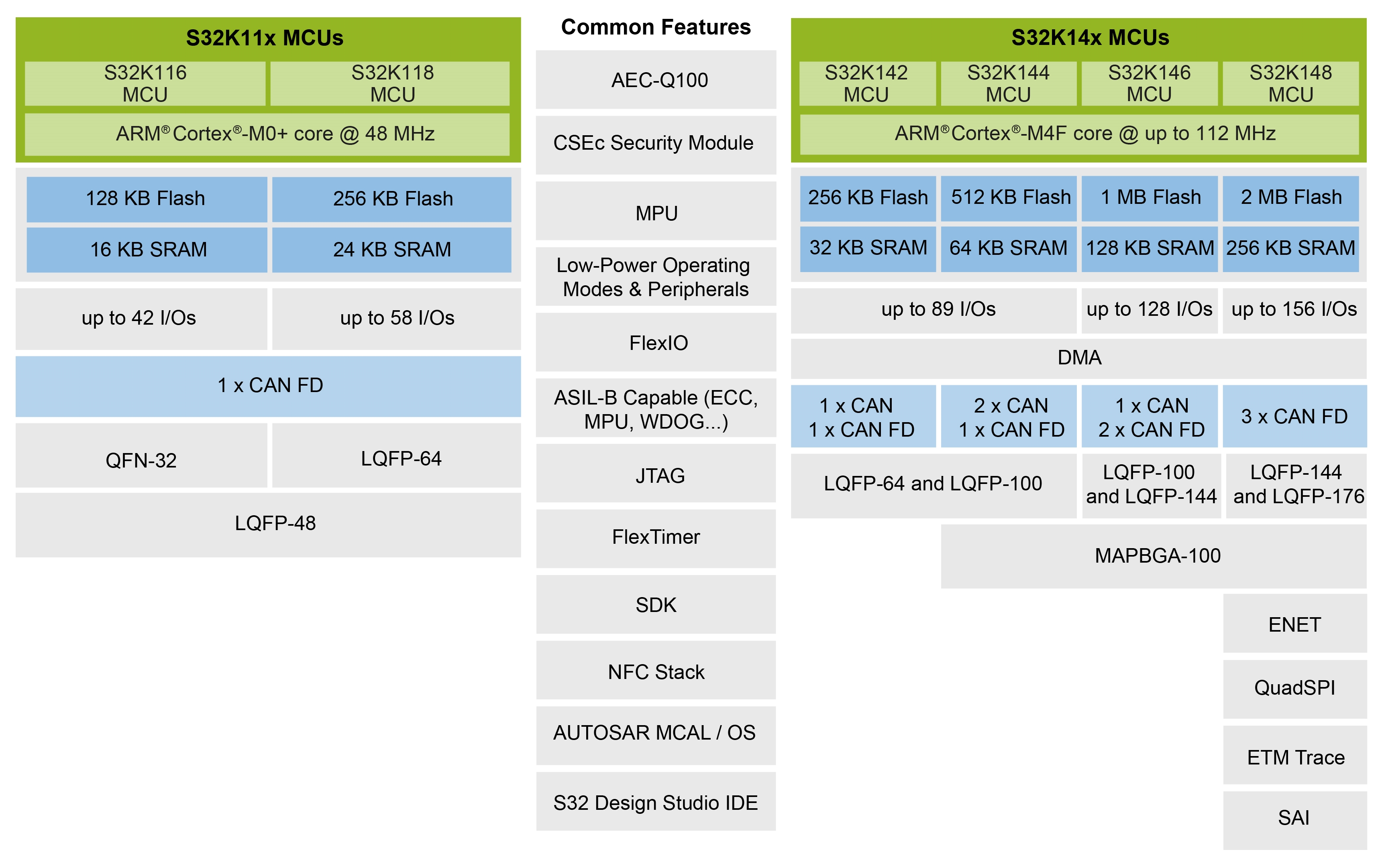
AUTomotive Open System Architecture (AUTOSAR) is a worldwide automotive consortium trying to create and establish an open and standardized software architecture for automotive electronic control units (ECUs). However, as is always the case with industry consortiums and standards, they are not endorsed by all interested parties, and, to complicate matters even more, not all applications require AUTOSAR.
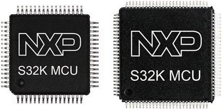
With this in mind NXP has launched its S32K1 family of scalable ARM Cortex-M devices together with a suite of automotive grade tools and software. Initially the family will span 128KB-2MB of flash memory. All family members include ISO CAN FD, CSEc hardware security, ASIL-B support and ultra-low-power performance. Check out the demo video.
Block Diagram
In applications where the use of AUTOSAR is not mandated, the S32K platform provides a path for self-development with a free-of-charge, pre-qualified, automotive-grade software development kit (SDK) that enables rapid prototyping with simple drag and drop functionality. For AUTOSAR applications, NXP’s MCAL and OS support has been expanded with new Complex Device Drivers (CDD) and a new S32K starter kit is available free of charge for evaluation.
You can learn more about NXP’s S32K1 product line and the suite of automotive-grade tools and software that support ARM Cortex-based MCUs at the official website.
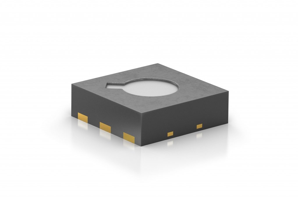
At this year’s Sensor+Test 2017 in Nuremberg (May 30 – June 1), Sensirion AG, the expert in environmental and flow sensor solutions, introduces the SGP – a siloxane resistant metal-oxide gas sensor with unprecedented long-term stability.
The SGP gas sensor is based on Sensirion’s multi-pixel platform, which integrates four gas sensing elements into a very small 2.45 x 2.45 x 0.9 mm3 DFN package featuring a fully calibrated air quality output signal. The unique combination of long-term stability and multi-pixel technology opens up new possibilities for environmental monitoring in smart home, appliances and Internet of Things applications. Thanks to its unique performance, the SGP allows the integration of metal-oxide gas sensors into mobile devices.
Sensirion solves long-standing stability problem in metal-oxide gas sensors – [Link]