Kionix (Ithaca, New York), part of the Rohm Group, has added the KXTJ3 3-axis low-cost accelerometer that offers the performance of a more expensive accelerometer in a 2 x 2 x 0.9 mm form factor. By Graham Prophet @ eedesignnewseurope.com
The company presents the device as a high performance and reliable accelerometer in a package that is sized and priced to be embedded in anything and everything, from toys, wearables, remote controls to the SmartHome and IoT.
3-axis accelerometer performs wake-up in consumer designs – [Link]
Arrow Electronics has introduced a new FPGA IoT Maker Board designed for end-to-end application development and optimised for cost. The Arrow MAX1000 board can be installed directly into a custom application or integrated on to a completely separate board.
It has been created for start-ups, universities or established equipment manufacturers who want a flexible, low cost FPGA platform for development, and the distributor can also supply customised variants.
At the heart of the maker board is a compact (11x11mm) Intel MAX10 FPGA with 8000 logic elements. This single chip includes integrated flash memory, a 1Msps 12bit ADC for analogue signals and a 3.3V power supply. Other features include embedded SRAM, DSP blocks, instant-on within milliseconds, and the ability to implement Intel’s NIOS II soft core embedded processor to perform microcontroller tasks. The board is equipped with an integrated Arrow USB-Blaster that enables the FPGA to be programmed directly from a PC and debugged using the free of charge Intel Quartus Prime Lite software.
The MAX1000’s power can be supplied as 5V from the USB port or via a separate pin. An Enpirion DC/DC converter with integrated coil then generates the 3.3V supply used on board. A MEMS oscillator provides the clock supply for the FPGA and the USB bridge. The low power, 3-axis acceleration sensor – also based on MEMS technology, can be used for position and motion detection, which are often required in IoT applications. External SDRAM can be used for storage of application data or as memory for the NIOS II processor.
Afroman reviews Siglent’s SSA3000X series spectrum analyzer and all the options. There is some RF information for beginners and usage experiments are also performed.
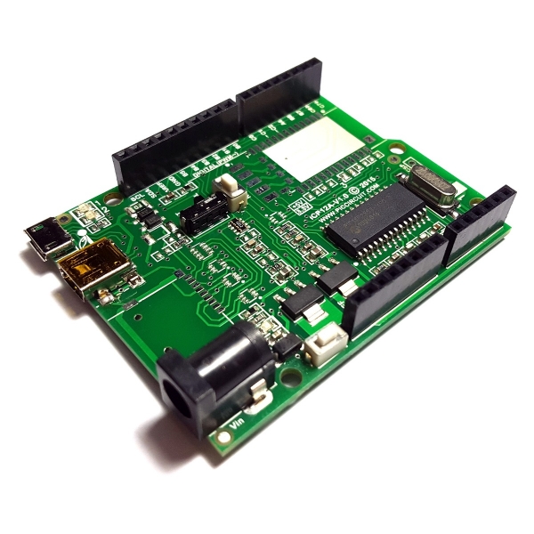
iCircuit Technologies had produced the iCP12A DAQduino, an Arduino-like development board for signals monitoring, data acquisition and circuit troubleshooting at 1mSec/Samples period.
The DAQduino board features a PIC18F2550 microcontroller with 14 digital I/O pins, two of them are PWM, and 6 input analog pins. With these IO ports, user can easily plug in different type of 3rd party boards with direct connection to USB port.
DAQduino has the same concept of the ICP12 usbStick with different shape and more I/O pins. Its PIC MCU is preloaded with Microchip’s USB HID bootloader that allows users to upload an application firmware directly through a PC’s USB port without any external programmer.
Features of iCP12A:
Arduino form connection, easy interfacing, high performance and user friendly device
Onboard with PIC18F2550 [Default] or PIC18F2553 28-Pin Flash USB PIC MCU
Excellent flexibility that allows user to expand the board features with plug and play modules
Peripheral Features:
19x IO Port (6x 10/12bit ADC pins, 2x 10 bit PWM/Freq/DAC pins)
Serial port emulation (UART Baud Rates: 300 bps to 115.2 kbps)
Supported operating systems (32bit/64bit): Windows XP ,Windows Vista, Windows 7, Windows 8, Windows 10, Linux, Mac OS X and Raspberry Pi
On board Female Mini USB and Micro USB Type B connector
Maximum Input Voltage: 15Vdc
With 500mA current output at VDD pin with over-current protection
20MHz oscillator
Green LED – power on indicator
2x LEDs (Green, Red) – status indicator
ICSP Connector – on-board PIC programming
Switch Mode Selection – Boot or Normal mode
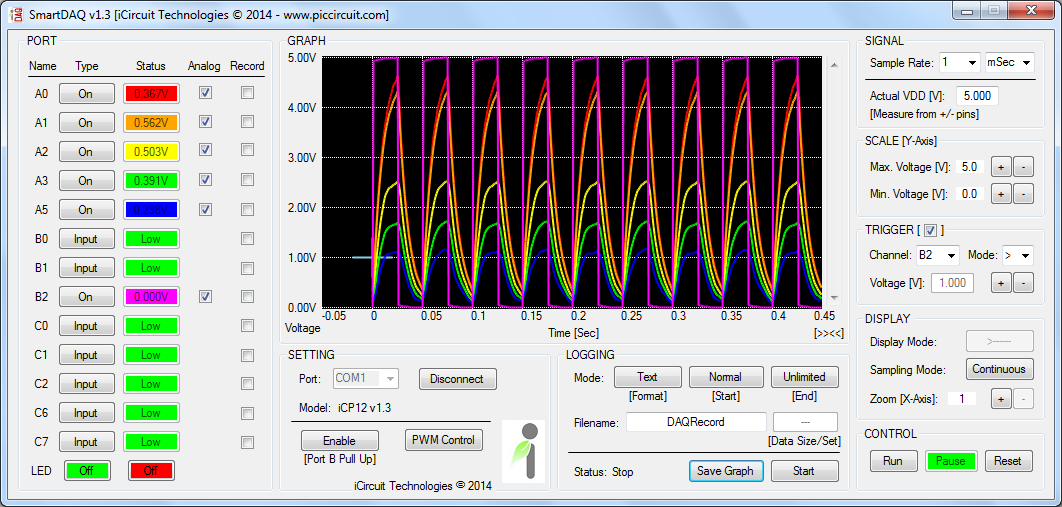
DAQduino board is shipped with a preloaded data acquisition firmware that emulates as a virtual COM port to PC. Thereafter, the communication between the PC and DAQduino is serial and through a miniUSB cable. The firmware also supports basic I/O control and data logging feature. They provide a PC application named SmartDAQ that communicates with the DAQduino and controls its I/O pins, PWM outputs, and record ADC inputs.
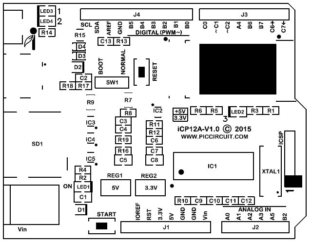
iCP12A DAQduino Layour
SmartDAQ has a very friendly GUI with real-time waveform displays for 6 analog input channels. The time and voltage axes scales are adjustable. SmartDAQ can log the ADC data in both text and graphic form concurrently. One can utilize this feature to construct a low-cost data acquisition system for monitoring multiple analog sensor outputs such as temperature, accelerometer, gyroscope, magnetic field sensor, etc.
Start Time: Normal, Once Trigger, 24-Hour Clock (Auto Run)
End Time: Unlimited, Data Size, 24-Hour Clock (Auto Stop)
SMARTDAQ1.4 Window
The DAQduino is available with the PIC18F2550 for $30, and with the PIC18F2553 for $39.9. You can order it through the official page where you can also get more details about iCP12A and its source files.
You can also see this product preview to know more about its functionality.
Our ‘common sense’ would say that when an object moves from point A to point B it necessarily has to also move through all the points between A and B. This is, however, not true for electrons in the quantum world, where these intuitive truths are not valid. Electrons can, for example appear on the first floor and then on the third floor – without ever putting a foot down on the second floor (insofar that electrons have feet, of course).
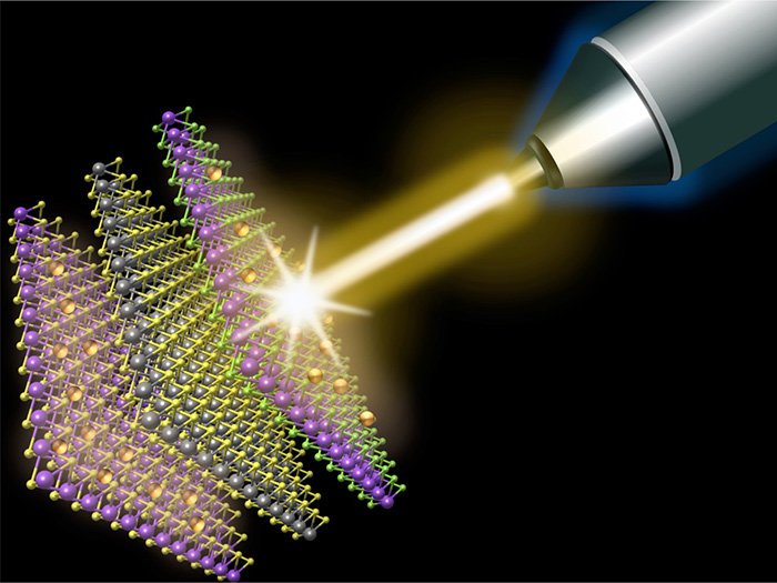
Exactly this counter-intuitive behavior has been observed by professor Hui Zhao and his colleagues in the Ultrafast Laser Lab of the University of Kansas. In the sample, which consists of three different, ultra thin layers, electrons move from the top layer to the bottom layer without ever having been observed in the middle layer. According to Zhao this efficient form of quantum electron transport could play a key role in so-called Van der Waals materials, which have their uses in solar panels and in electronics in general.
The sample that was the subject of the research comprises three layers of semiconductor materials (MoS2, WS2 and MoSe2), each with a thickness of less than 1 nm. These three materials react to light of different wavelengths (colors).
The researchers used a laser pulse with a duration of 100 femtoseconds to knock a few electrons from the topmost MoSe2 layer so that they were able to move freely. With a laser pulse of the correct color for the bottom MoS2 layer (which, thanks to the difference in path length of 0.3mm, arrives one picosecond later than the first pulse), the appearance of the electrons in the bottom layer could be demonstrated. It appeared that the electrons on average needed 1 ps to move from the top layer to the bottom layer.
With a third laser pulse the middle layer was monitored – but no electrons on their way from the top to the bottom were ever observed there. Apparently the electrons ‘jumped over’ the middle layer – a behavior that has also been confirmed through simulations by theoretical physicists at the University of Nebraska-Lincoln.
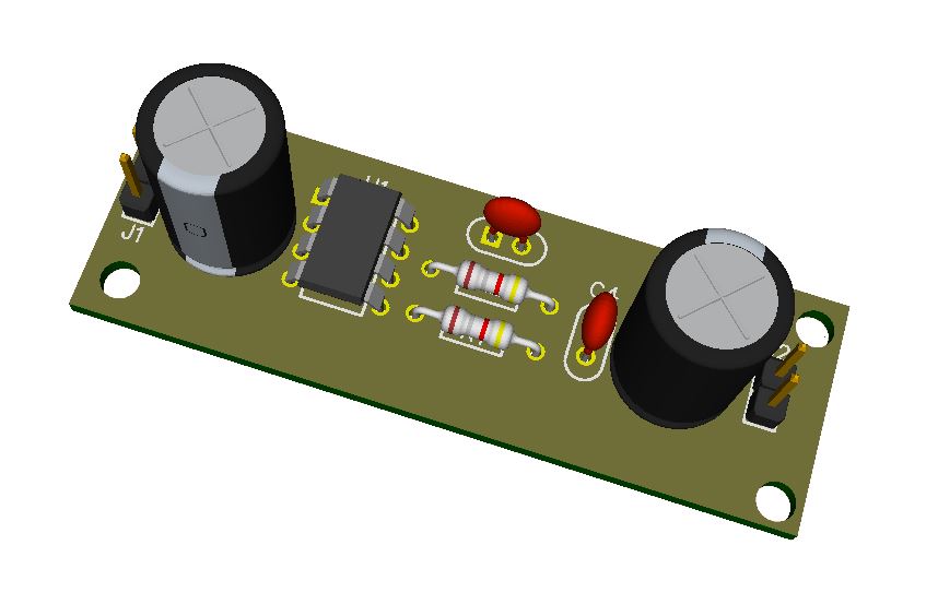
The circuit diagram presented here is about a negative voltage regulator. It is based on LT1054, which is a switched capacitor voltage converter with regulator from Texas instrument. This device has many advantages over other previously available switched capacitor voltage converters. It provides higher current and has lower voltage losses.
Open Panzer Project is an attempt to create open source versions of all electronics used in RC tanks today, with professional quality and features. The goal of this project is to expand the hoppy and to improve everyone’s experience of RC tanking corner, which will speed-up its growing.
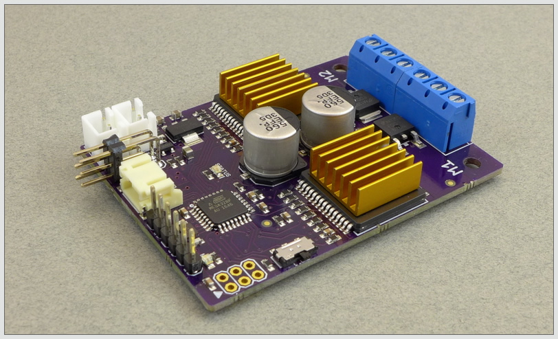
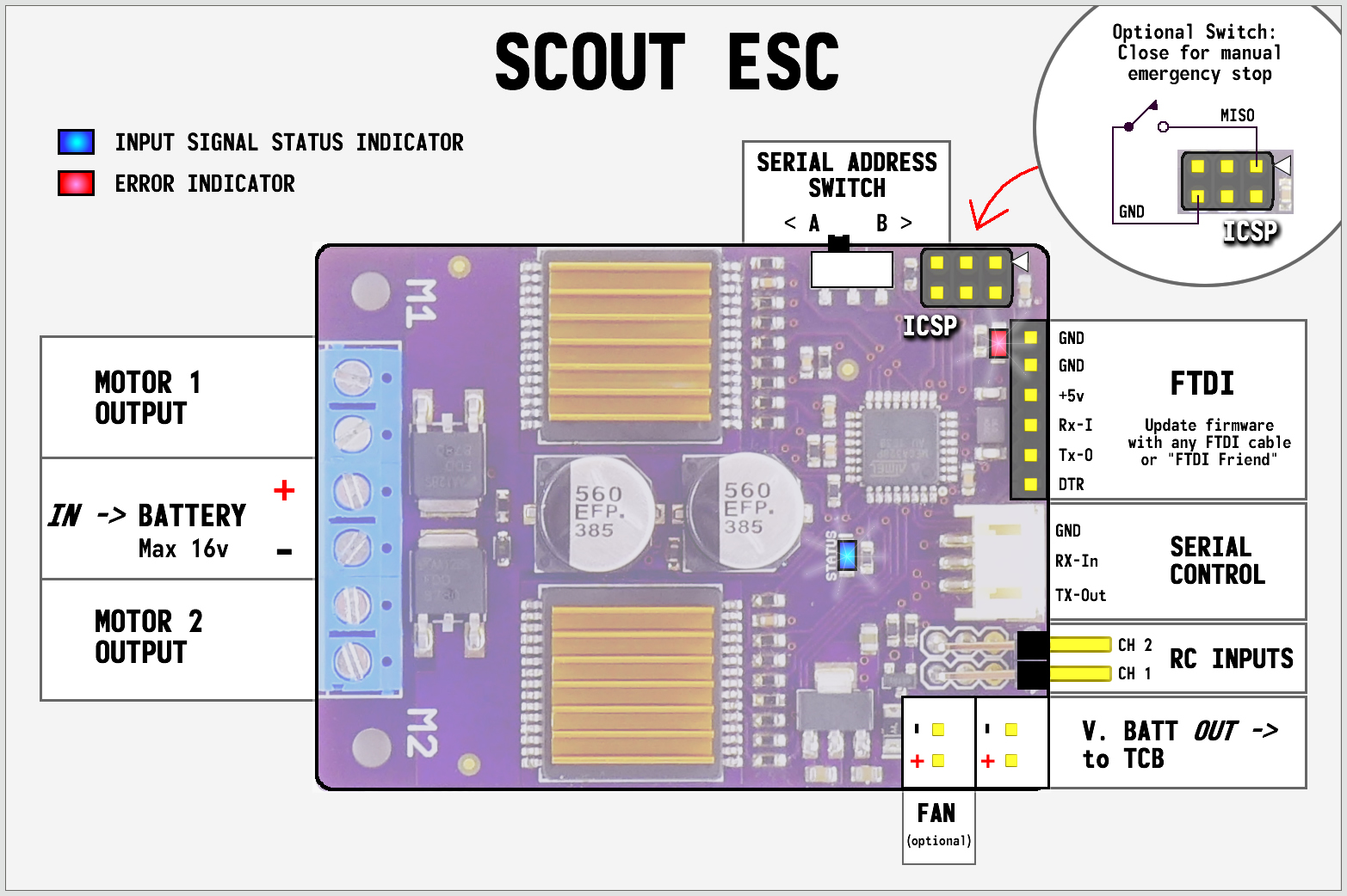
Open Panzer recently developed the Scout ESC board, a dual brushed-motor speed controller that accepts both standard RC inputs or logic-level serial commands. It features an ATmega328 that can be programmed with the Arduino IDE through standard FTDI cable.
The Scout ESC operates at ultrasonic frequencies, at voltages up to 16 volts, and is rated at 10 amps continuous per channel, but the addition of a fan can increase the current capacity. The Scout has its own onboard fan controller that can drive any standard 12 volt 2-pin PC case fan. An onboard thermistor also allows the processor to monitor the board temperature.
The Scout is 65mm x 47mm board that is perfect for controlling even the heaviest 1/16th scale RC tanks. It is compatible with the Open Panzer Tank Control Board, so no additional setup is required.
Scout ESC specification:
Input voltage: 6 – 16 volts
Operating current:
10 amps per channel continuous without fan
20 amps peak
Motor PWM: 21 kHz
RC Inputs: Standard 1000-2000 uS pulse width (1500 uS = motor stopped)
Serial Input: 38400 baud; 8 data bits, no parity, one stop bit; TTL level (5v max)
Dimensions (L x W): 2.6″ x 1.9″ / 65mm x 47mm
Mounting holes: 1.57″ / 40mm (use 4-40 or 3mm screws)
As it is an open source project, you can get Scout board files, schematics, and bill of materials from the website, and the firmware and libraries from the github repository. The Open Panzer wiki has more information about the project, and the Open Panzer Community is open for everyone for discussion.
Graham Prophet @ eedneurope.com presents the latest ultra-low dropout regulators from Diodes Inc:
The AP7380 series of ultra-low dropout regulators (Diodes Inc.) operates from an up-to-24V input voltage range and offers fixed output voltage options, in USB power, portable equipment, consumer, instrumentation and metering applications.
Ultra-low dropout, wide input range 150mA regulator – [Link]
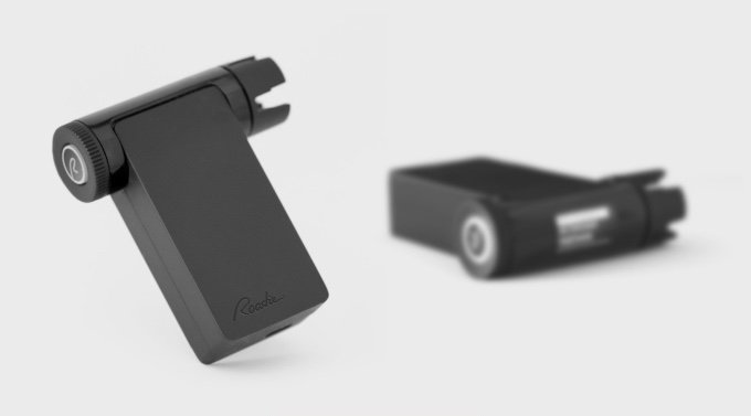
Roadie Tuner is a dream come true for guitarists! The automatic ring tuner, that is quick, easy to use, and three times more accurate than the human ear, is dedicated to beginner guitarists who are almost always frustrated with not knowing how to tune their guitar. This ultimate musician’s tool works on all string instrument to fine tune them in seconds, including bass guitars.
Roadie Tuner pairs with a free app on your smartphone, iPod or tablet through Bluetooth 4.0 smart. All the audio processing happens on the smartphone which sends tuning commands to Roadie. You can choose from a list of alternate tunings or you can easily create your own.
You can set up a profile for your instrument in Roadie Tuner app and it will track its maintenance history. Thus, it will inform you of the quality of your strings and recommend restringing as soon as the tone quality deteriorates.
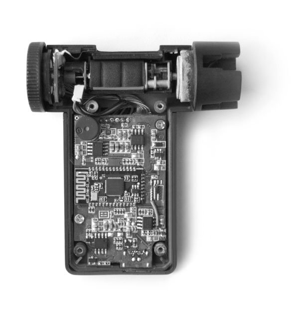
Roadie tuner team had just launched their second version of this amazing product, Roadie 2. The new about this tuner the fact that it is fully standalone and uses vibration detection to tune in even the noisiest of environments. Thus, no need to be paired with a mobile app anymore to tune your instruments.
Below are Roadie 2 technical specifications:
Metallic gearbox: Built with a 380:1 gear ratio motor that insures Roadie 2 will turn those rusty pegs for you. The motor can turn in micro-movements to achieve unparalleled precision.
Battery:Powered by a rechargeable Lithium Ion battery (included). Lasts 1 month on a single charge. Includes a battery indicator to show you how much juice is left.
USB-C: With a charging cable included.
Built-in user interface: For easy selection of instruments and tunings.
Bluetooth 4.0 low energy
Haptic feedback: When a string is in tune, Roadie will give you a little shake to move on to the next string.
OLED screen Invisible when off, lights up beautifully as soon as you turn Roadie 2 on.
Knob interface: Intuitive and fast to scroll through your instruments and tunings.
“I think the concept is fantastic and I would be thrilled to have one of these because I actually play twelve string guitars. You don’t know how bloody difficult it is to keep a twelve string in tune” – Spike Edney, Queen
More details about extra features within the Roadie Tuner app, the product versions and more are available at the Kickstarter campaign the team had launched 2 days ago. Within only 3 hours, the campaign had achieved its goal and it is already 300% funded. Early bird offers still has 8 hours to go, you can pre-order your own Roadie for $79! Also check out the official website for more information.
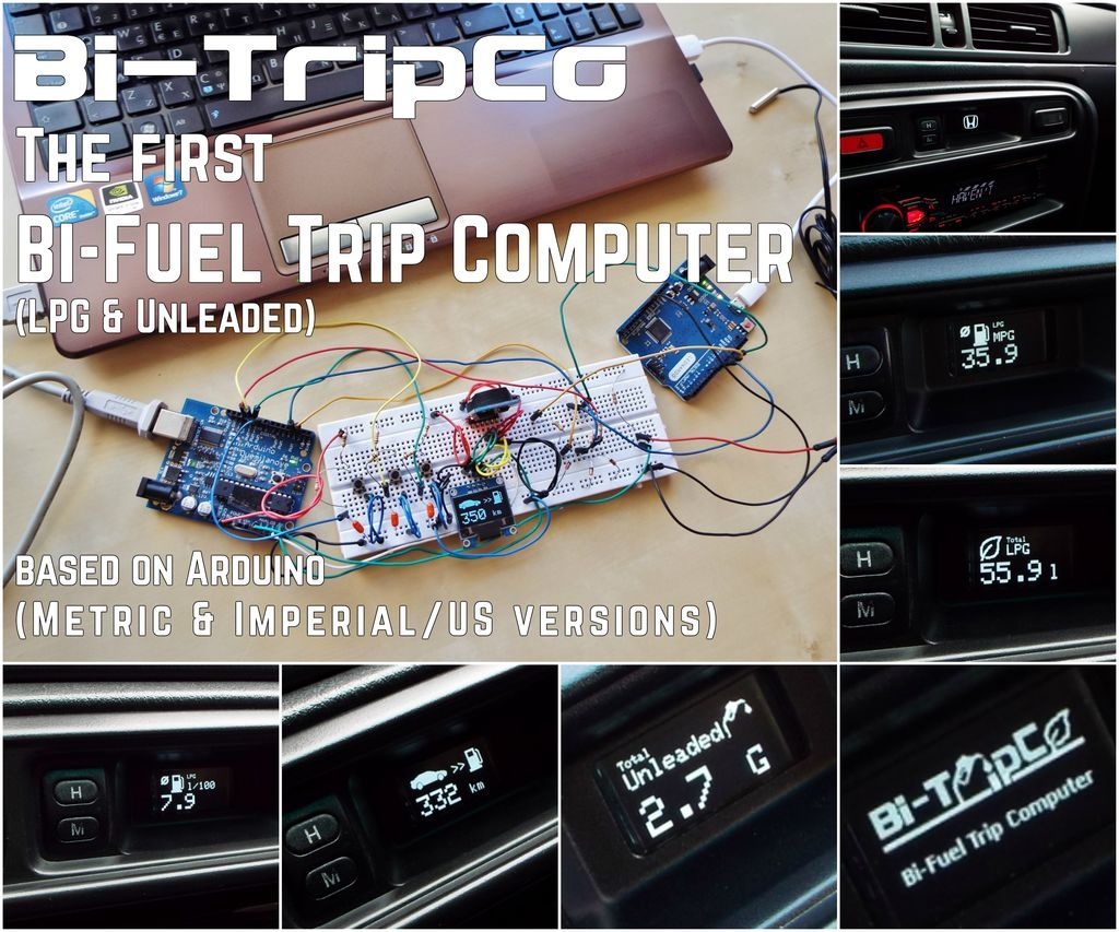
Nikos Stavrou @ instructables.com build a bi-fuel trip computer using arduino and has a detailed tutorial on it. The computer can measure both LPG and unleaded fuel consumption. He writes:
The main reason I made this project is the lack of a trip computer that is designed for LPG powered cars.
I named it Bi-TripCo as it can measure the fuel consumption for both fuel systems of a Bi-Fuel car (LPG and Unleaded).
Some might say: “ok, a similar one, no big deal!”. Don’t rush.There are many (or some) tools out there, that can calculate the consumption of conventional fuel systems, which are very easy to use: just plug it into the OBD port of your car – unless you have an older car which does not have one, like mine. And, of course, there are some very good implementations based on Arduino, which can calculate many things related to the Unleaded fuel consumption. But those tools can not be used on an LPG powered car.
How to Build a Bi-Fuel (LPG & Unleaded) Trip Computer Using Arduino – [Link]