10-bit resolution, 70-300 MHz, touchscreen scope priced from €1250

by Graham Prophet @ edn-europe.com:

Rohde & Schwarz recently announced its RTB2000 entry-level oscilloscope, aimed at education, R&D and manufacturing. With an starting price of €1,250, the company says it provides performance previously only available in higher priced oscilloscopes.

10-bit resolution, 70-300 MHz, touchscreen scope priced from €1250 – [Link]

Step‐up DC/DC converters with built‐in inductors and control ICs

Measuring 2.5×2.0×1.0mm, the newly‐developed XCL102/XCL103 series of step‐up micro DC/DC converters is designed with built‐in inductors and control ICs. By Julien Happich @ edn-europe.com:

The use of built‐in inductors also allows PCB layouts to be simplified, minimizing unwanted radiation noise and operational trouble. The input voltage can be selected from 0.65V (operation hold voltage) to 6.0V, and the output voltage from 2.2V to 5.5V

Step‐up DC/DC converters with built‐in inductors and control ICs – [Link]

AT88CK490, A New Atmel CryptoAuthentication USB Dongle Evaluation Kit

Atmel had produced a new USB evaluation kit “AT88CK490” to evaluate the performance and applicability of the Atmel Family of CryptoAuthentication devices. The kit contains three devices; ATSHA204, ATAES132, and ATECC108.

AT88CK490 Kit devices are based on Atmel AT90USB1287 microcontroller which provides a convenient USB 2.0 interface allowing users to understand and experiment with the CryptoAuthentication devices. Developers can use the provided 5-pin interface at the end of the board and can be used to monitor the I2C protocol.

This kit gives engineers, developers, and decision makers a tool to understand the device architecture and its usages for product authentication, confidential file protection, performing two-factor logons, or preventing software piracy.

CryptoAuthentication USB Dongle Kit Features

  • Atmel ATAES132A CryptoAuthentication IC: I2C Address (0xA0)
  • Atmel ATSHA204A CryptoAuthentication IC: I
  • 2C Address (0xC8)
  • Atmel ATECC108A CryptoAuthentication IC: I2C Address (0xC0) – AT88CK490 Only
  • Atmel ATECC508A CryptoAuthentication IC: I
  • 2C Address (0xC0) – AT88CK590 Only
  • Atmel AT90USB1287AVR
    • 128KB of In-system Programmable Flash
    • 4KB EEPROM
    • 8KB Internal SRAM
  • USB 2.0 Full Speed Device
  • Power LED (Red)
  • Three Status LEDs (Blue)

Atmel CryptoAuthentication is a crypto element device family with ultra-secure hardware-based key storage. It is used to ensure that the product and its accessories are original and are not counterfeited. CryptoAuthentication devices support modern cryptographic standards. They are cost-effective, require only a single GPIO, use very little power, operate over a wide voltage range, and work with any MCU.

The AT88CK490 evaluation kit has been designed to work with the Atmel CryptoAuthentication Evaluation Studio (ACES) configuration environment GUI. The complete source code for the Atmel AVR® is available, along with a schematic, a bill of materials, and Gerber files.

Call for Makers: Hackaday Prize for Social Impact Projects

In patnership with Digi-Key, Supply Frame and Microship, Hackaday is calling for the curious, the creative, and the determined who are working to create social change in order to transform the world using their hardware and programming knowledge in addition to scientific, design, and mechanical abilities. This contest by Hackaday will encourage people innovate projects that can impact in people lives.

All you have to do is designing an impactful project that suits you, or collaborate with a team to do it. You can create things like reliable utensils for the disabled, a way for denizens to find clean drinking water in rural villages, refreshable braille displays for image text and a smart home to build a sustainable community. Or go beyond that and create something that has never been seen before. The purpose of the contest is to encourage participants to develop solutions to address technology issues facing humanity today.

With the global collaboration behind this contest, the total prizes will reach $250,000 and they will be divided as following: $120,000 goes to top 120 finalists ($1,000 each), $50,000 Grand Prize, $30,000 Best Product Prize, $20,000 2nd Place, $15,000 3rd Place, $10,000 4th Place and finally a$5,000 5th Place.

The first stage of the Contest will consist of five (5) Challenge Rounds. Participants may enter the Contest during any of the Challenge Rounds. Up to twenty (20) entries from each Challenge Round will be chosen to advance to the final round. Participants must complete the requirements for at least one (1) Challenge Round to be eligible for the final round. An entry may be submitted to any or all of the Challenge Rounds as long as it meets the requirements for each Challenge Round in which it is submitted. All submissions must be in English and must comply with any specified requirements.

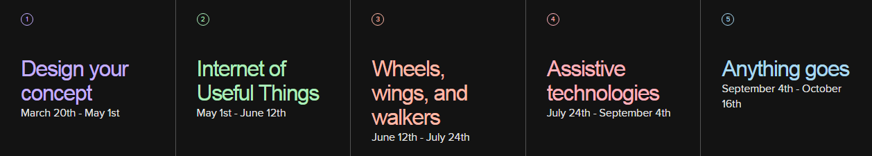
Challenge Round 1: (Get Started: Design Your Concept.)

Entry period begins 7:01 a.m. P.D.T on March 20, 2017 and closes 7:00 a.m. P.D.T on May 1, 2017. This round is for showcasing your idea, hacks and logs and presenting the problem and how will your project solve it.

Challenge Round 2: (Internet of Useful Things :: IuT ! IoT)

Entry period begins 7:01 a.m. P.D.T on May 1, 2017 and closes 7:00 a.m. P.D.T on June 12, 2017.
Let’s take Internet of Things and make it practical for everyday life. Internet of Useful Things projects showcase a way to build a better tomorrow with the data you track and analyzeChallenge

Round 3: (Wheels, Wings and Walkers)

Entry period begins 7:01 a.m. P.D.T on June 12, 2017 and closes 7:00 a.m. P.D.T on July 24, 2017. This round is for building things that move, so the objective of the project is movement and support for things that help move humanity forward.

Challenge Round 4: (Assistive Technology)

Entry period begins 7:01 a.m. P.D.T on July 24, 2017 and closes 7:00 a.m. P.D.T on September 4, 2017.  Assistive technology projects ensure a better quality of life for the disabled and enhance learning, working, and daily living.

Challenge Round 5: (Anything Goes)

Entry period begins 7:01 a.m. P.D.T on September 4, 2017 and closes 7:00 a.m. P.D.T on October 16, 2017. No reservation, no theme, no topic. it is up to you to build on your idea that resonates with you and encompasses the spirit of making. Build whatever you think would benefit humans and the world we live in.

Best Product

To be eligible for Best Product the product must not have received more than $2,000,000 in funding within the life of the product. The sum of the product’s dimensions (width + height + depth) must total 36 inches (91.44 centimeters) or less. Best Product Final Round. By 1:50 p.m. P.D.T. on October 21, 2017

It’s time to leverage your talent and find solutions to address a problem facing humanity today. With a new technical design challenge every 6 weeks, you are expanding the frontiers of knowledge and engineering.

In order to bootstrap your project before completing your final application of this contest, Hackaday now gives you the chance to participate in a public voting and win up to $200. Just start your entry to get access to this.
Check the rules of the contest to make sure that your country is eligible to apply. Also check this page to know more details about the contest.

GPS tracking with an MSP430F5510 over GPRS

Bluehash over at 43oh.com writes:

I found a tiny gem while browsing Github for MSP430 projects. This one is a GPS tracker based on a MSP430F5510 with a GPRS cellular connection for reporting and command input. The GPS is a FGPMMOPA6H from GlobalTop and the GPRS module is a SIM900 from Simcom.
The Github link has details from code to schematics and board files.

GPS tracking with an MSP430F5510 over GPRS – [Link]

Roshamglo Badge, The Rock-Paper-Scissors kit by SparkFun

The SparkFun Roshamglo is the new and fun way to play Rock-Paper-Scissors with your friends! The board uses the ATtiny84, and has an IR LED and receiver to communicate between badges. To play, simply point the USB connector at your opponents Roshamglo up to 5 feet away and press the 5-way switch to the left for rock, up for paper, and right for scissors. The red/green LED will display a solid red for lose, green for win, or alternate red and green for a tie. Your Roshamglo can also be worn with a lanyard clip to provide you easier access when a battle is about to ensue!

The Roshamglo Badge comes as an easy to assemble kit that only requires you to solder on six battery clips to the underside of the board and insert three AAA sized alkaline batteries. No other soldering or programming is required! Once you install the clips and batteries you can start playing Rock Paper Scissors with a friend or start hacking your Roshamglo.

The Roshamglo uses the Micronucleaus bootloader, which allows for programming from the Arduino IDE via the USB connector at the front of the board. We have included two tutorials below to help teach you how to hack your new Roshamglo as well as turn it into a remote to control to turn on and off most styles of televisions!

Features:

  • 8kB of flash memory for our program (~6kB after the bootloader is installed)
  • 512B of SRAM, which stores our variables used in our program
  • 512B of EEPROM
  • 12 IO pins MAX (the Roshamglo breaks out 9 of these pins)
  • 10-bit analog to digital converter which can be used on 8 pins
  • IR LED
  • IR receiver with built in 38kHz demodulator
  • USB programming
  • Programmable red and green LED
  • Power switch
  • 5-way switch for input
  • Reset switch

Roshamglo comes with 3x AAA Alkaline batteries and a 6x AAA battery holder and you can order it now for $12.95.
You can also check the product page for more technical details and source files. Also check this guide to know how to use the Roshmalgo Badge from SparkFun.

Source: SparkFun

Snapmaker, The Modular & Multi-Functional 3D Printer

Snapmaker is a Kickstarter project with a lofty goal: to be the holy trinity for at-home makers by using detachable modules to convert between a 3D printer, a CNC carver, and a laser engraver. In retrospect, the idea seems almost obvious. All three devices need three-axis motors to work: so why not combine them into one?

But Snapmaker doesn’t just stand out for its modular nature — it’s also impressively cheap. The default Snapmaker costs $299 on Kickstarter, and includes just the 3D printer. The laser engraver and CNC modules then each cost $75, making the entire package cost $449 — which would be a pretty good price for just one of these devices, let alone all three.

Snapmaker also claims that it’s offering a fairly high-quality printer for the price, with an “all-metal” construction and 3.2-inch color touchscreen. When it comes to actual specifications, the 3D printing module can print items up to 125 x 125 x 125mm in size at a resolution of 50–300 microns. When it comes to engraving, the laser module offers a 500mW beam that can work with wood, bamboo, leather, plastic, fabric, and paper. And the CNC module can carve wood, acrylic, and PCB at speeds between 2,000 and 7,000 RPM.

Obviously, these are some pretty big promises to be making, especially at the relatively low price point that Snapmaker sells for. And as a first time, crowdfunded project from a new company that has yet to ship a product before, the burden is on Snapmaker to show that they can actually deliver. And while the company has posted videos to YouTube demonstrating the various modules in action, at the price that Snapmaker is selling, it’s possible the whole thing is too good to be true.

The crowdfunding campaign still has 35 days to go, and is already 130% funded! Check out the technical details at the official website.

Source: The Verge

ICP12 USBSTICK, A New Tool for Signals Control & Monitoring

iCircuit Technologies had produced the iCP12 usbStick, a mini size 28 pin USB PIC IO development board and a good tool for signal monitoring (as oscilloscope), data acquisition and circuit troubleshooting at 1mSec/Samples period.

The iCP12 usbStick is a PIC18F2550 based USB development board that comes preloaded with Microchip’s USB HID bootloader which allows users to upload an application firmware directly through a PC’s USB port without any external programmer. It provides access to its I/O pins through 0.1″ pitch headers. A slide switch is also provided on board to select the operation of the board in Bootloader or Normal mode.

The features of iCP12 are listed as following:

  • Mini size, easy interfacing, high performance and user friendly device
  • Used with PIC18F2553 28-Pin Flash USB PIC MCU
  • Excellent flexibility that allows user to expand the board with plug and play modules
  • Peripheral Features:
    • 13x IO Port (6x 12bit ADC pins, 2x 10 bit PWM/Freq/DAC pins)
    • Serial port emulation (UART Baud Rates: 300 bps to 115.2 kbps)
    • Supported operating systems (32bit/64bit): Windows XP ,Windows Vista, Windows 7, Windows 8, Windows 10, Linux, Mac OS X and Raspberry Pi
    • Maximum Voltage: 5Vdc
    • 100mA current output at VDD pin with over-current protection
    • 20MHz oscillator
    • Green LED – power on indicator
    • 2x LEDs (Green, Red) – status indicator
    • ICSP Connector – on-board PIC programming
    • Switch Mode Selection – Boot or Normal mode

The iCP12 usbStick board is shipped with a preloaded data acquisition firmware that emulates as a virtual COM port to PC. Thereafter, the communication between the PC and usbStick is serial. The firmware also supports basic I/O control and data logging feature. They provide a PC application named SmartDAQ that is specially developed to communicate with the usbStick and control its I/O pins, PWM outputs, and record ADC inputs.

SmartDAQ has a very friendly GUI with real-time waveform displays for 6 analog input channels. The time and voltage axes scales are adjustable. SmartDAQ can log the ADC data in both text and graphic form concurrently. One can utilize this feature to construct a low-cost data acquisition system for monitoring multiple analog sensor outputs such as temperature, accelerometer, gyroscope, magnetic field sensor, etc.

SmartDAQ v1.3 Features:

  • Sampling channel: 6x Analogs (12bits ADC/1mV Resolution) + 7x Digitals (Input/Output)
  • Maximum Sampling rate: 1KHz or 1mSec/Samples
  • Sampling voltage: 0V – 5V (scalable graph) at 5mV Resolution
  • Sampling period:
  • mSec: 1, 2, 5, 10, 20, 50, 100, 200, 500
  • Sec: 1, 2, 5, 10, 20, 30
  • Min: 1, 2, 5, 10, 20, 30, 60
  • Trigger Mode: Larger [>], Smaller [<], Positive edge [↑], Negative edge [↓]
  • Sampling Mode: Continuous, Single
  • Logging Function:
  • Save Format: Text, Graphic, Both
  • Start Time: Normal, Once Trigger, 24-Hour Clock (Auto Run)
  • End Time: Unlimited, Data Size, 24-Hour Clock (Auto Stop)
  • Recorded Data format: Graphic | text | excel

iCP12 is available with the PIC18F2550 for $15, and with the PIC18F2553 for $24.5. You can order it through the official page where you can also get more details about iCP12 and its source files.

You can also see this product preview to know more about its functionality.

ReRAM, Process Data Where They Are Stored

Because data storage and processor are separated from each other, moving data between the storage and the computation unit became a main factor in computing.
Many techniques were developed to speed up this process, such as pipelining, caching, and look-ahead execution, but “ReRAM” appears as a new technique to solve the root of the problem by merging memory and processor together.

Resistive RAM, which known as RRAM or RERAM, is the new generation of memories. Its cells are simpler than classic transistor-based memory cells, they are non-volatile, switch fast and can run from low voltages. Researchers now have managed to make RERAM cells store more than just a ‘0’ or a ‘1’, enabling in-place computations.

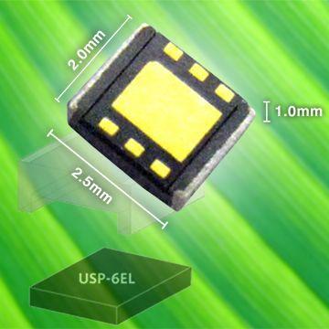
The first small memory devices based on this technology is the MB85AS4MT, that was developed by Fujitsu Semiconductor with Panasonic Semiconductor Solutions. MB85AS4MT is a 4 Mbit ReRAM chip that operates with a supply voltage in the range from 1.65 to 3.6 V and has an SPI interface. One of the stand-out features of this technology is its low operating current, just 0.2 mA, at a maximum read speed of 5 MHz.

Using so-called RERAM crossbar arrays, researchers have demonstrated the in-memory execution of binary matrix computations frequently encountered in high-performance computing, algebraic cryptanalysis, combinatorics and finite geometry data, and in general large scale data analysis. Although we are only at the beginning of this technology, the results are already promising.

More mathematical details can be found in this paper.

Source: elektor.

5V to 12V @400mA Boost Converter

The circuit presented here is about a boost converter based on LM2698. It is a PWM boost converter from Texas instruments. LM2698 can also be used as a flyback converter. The current mode architecture is a special feature of LM2698, which provides superior line and load regulation. This circuit is capable of a supplying a output voltage of 12V for a input range of 4.5V to 5.5V.

Specifications

  • Input voltage: 4.5VDC to 5.5VDC
  • Output voltage: 12VDC
  • Output current: 0.4A
  • PCB:45mm X 30mm

5V to 12V @400mA Boost Converter – [Link]

TOP PCB Companies