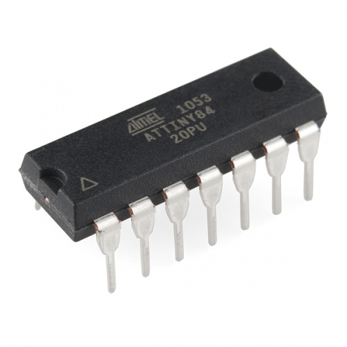
The Atmel AVR ATtiny84 is a $3 tiny 8-bit processor with 8K of program space, 12 I/O lines, and 8-channel 10 bit ADC. It will run up to 20MHz with an external crystal and can be programmed in circuit.
To start following the tutorial, you will need these parts:
Micronucleus is a bootloader designed for AVR ATtiny microcontrollers with a minimal usb interface, cross platform libusb-based program upload tool, and a strong emphasis on bootloader compactness. It has a built in V-USB so that you can send compiled firmware over a virtual USB connection.
The process will use an Arduino as a programmer by loading an Arduino ISP to install the micronucleus bootloader on the ATtiny84. The next step is allowing USB programming on ATtiny84 by manually change fuses, then creating a board definition for ATtiny84 and installing any necessary USB drivers.
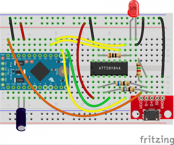
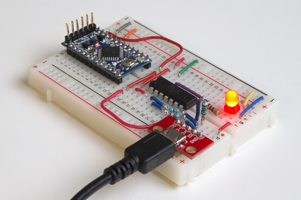
The hardware components should be connected as shown in the above circuit. At first you have to remove the capacitor and connect a FTDI breakout to the Arduino Pro Mini and upload the Arduino ISP firmware.
Before installing Micronucleus, a 10μF capacitor is added between the RESET and GND pins of the Arduino. It will prevent the Arduino from entering bootloader mode so that it will pass the compiled firmware to the connected ATtiny rather than trying to program itself.
AVRDUDE is used then to change the ATtiny fuses and set them as the following:
No clock divider
Brown-out detection at 2.7V (not necessary, but useful if running off battery)
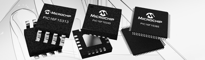
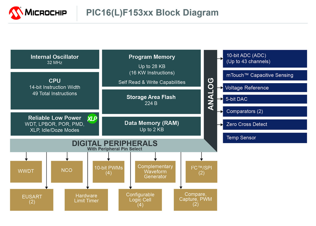
Microchip, the well-known manufacturer of microcontrollers and semiconductors, announced this week a new family of 8-bit PIC microcontrollers, the ‘PIC16F15386’.
The new PIC16F15386 family features a 8 MIPS CPU speed, with 2KB RAM and up to 28KB flash memory offered in 8 to 48-pin packages. It also has a dual UART, dual SPI and dual I²C interfaces, one 8-bit timer and two 16-bit timers.
PIC16F15386 Features
Enhanced Mid-range Core with 49 Instruction, 16 Stack Levels
Flash Program Memory with self read/write capability
eXtreme Low Power (XLP)
IDLE and DOZE low power modes
Peripheral Module Disable (PMD)
Peripheral Pin Select (PPS)
4x 10-bit PWMs
2x Capture, Compare, PWM (CCP)
Complementary Waveform Generator (CWG)
Numerically Controlled Oscillator (NCO)
4x Configurable Logic Controller (CLC)
43 Channels 10-bit ADC with Voltage Reference
5-bit Digital to Analog Converter (DAC)
2x Comparators
1x 8-bit Timers (TMR0/TMR2)
2x 16-bit Timer (TMR1)
Window Watchdog Timer (WWDT)
Enhanced Power-On/Off-Reset
Low-Power Brown-Out Reset (LPBOR)
Programmable Brown-Out Reset (BOR)
In Circuit Serial Programming (ICSP)
PIC16LF15386 (1.8V – 3.6V)
PIC16F15386 (2.3V – 5.5V)
PIC16F15386 family comes with essential peripherals like Intelligent Analog, Core Independent Peripherals (CIPs) and communication combined with eXtreme Low-Power (XLP) for a wide range of low-power applications. The family features PWMs, multiple communication, temperature sensor and memory features like Memory Access Partition (MAP) and Device Information Area (DIA).
We’ve always offered a diverse portfolio of products with large market appeal,” said Steve Drehobl, vice president of Microchip’s 8-bit MCU division. “With the combination of the most requested features and peripherals by our large base of PIC MCU users, the flexibility in memory size and package options and the availability of MPLAB Xpress with MCC, we expect the PIC16F15386 family to be popular with experienced and first-time PIC MCU designers.
The PIC16F15386 is also compatible with the MPLAB Xpress IDE and the MPLAB Code Configurator, a graphical programming environment. The family includes 13 unique products that are offered in various package options including PDIP, SOIC, DFN, UDFN, UQFN and SSOP.
All products are available now for sampling and in volume production. Volume pricing starts at $0.33 for the product family.
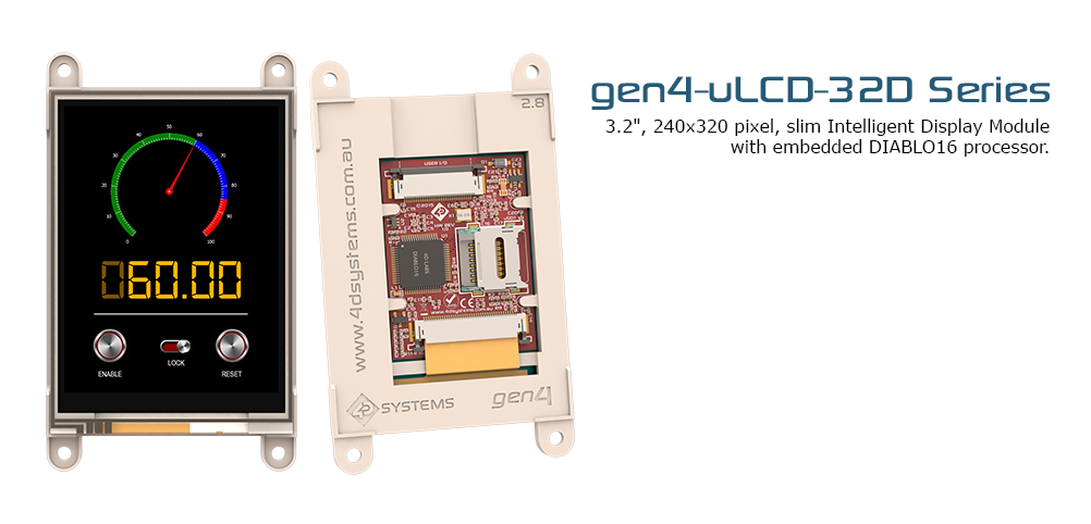
4D Systems, the manufacturer of intelligent graphics solutions, has announced a new 3.2” smart display module as part of the ‘ gen4 ’ series, which had been designed specifically for ease of integration and use, with careful consideration for space requirements and functionality.
These modules features a 3.2” color TFT display with options for Cover Lens Bezel (CLB), Resistive Touch and Capacitive Touch. The display is capable of Touch Detection, microSD memory Storage, GPIO and Communications, along with multiple millisecond resolution timers, and Audio Generation. gen4 modules have 30 pin ZIF socket for a 30 pin FPC cable, for easy and simple connection to an application or a motherboard.
The gen4 display modules are powered by the 4D Systems Diablo16 graphics processor that offers an array of functionality and options for any Designer / Integrator / User. Diablo16 is a custom embedded 4DGL graphics controller designed to interface with many popular OLED and LCD display panels.
gen4 display modules features:
Powerful 3.2” Intelligent LCD-TFT display module powered by DIABLO16.
240 x 320 Resolution, RGB 65K true to life colours, TFT Screen with integrated 4-wire Resistive Touch Panel (on DT model only).
6 banks of 32750 bytes of Flash memory for User Application Code and Data.
32Kb of SRAM purely for the User.
16 General Purpose I/O pins for user interfacing, which include 4 configurable Analog Inputs.
The GPIO is variously configurable for alternative functions such as:
3x I2C channels available.
1x SPI dedicated for SD Card and 3x configurable SPI channels available.
1x dedicated and 3x configurable TTL Serial comm ports available.
Up to 6 GPIO can be used as Pin Counters.
Up to 6 GPIO for PWM (simple and Servo).
Up to 10 GPIO for Pulse Output.
Up to 14 GPIO can be configured for Quadrature Encoder Inputs (2 channels).
30pin FPC connection, for all signals, power, communications, GPIO and programming.
On-board latch type micro-SD memory card connector for multimedia storage and data logging purposes.
DOS compatible file access (FAT16 format) as well as low level access to card memory.
Dedicated PWM Audio pin driven by WAV files from micro-SD card, and for sound generation, for an external amplifier.
Display full colour images, animations, icons and video clips.
Supports all available Windows fonts.
4.0V to 5.5V range operation (single supply).
Module dimensions:
(D): 95.7 x 57.1 x 6.3mm.
(D-CLB): 98.8 x 72.6 x 7.4mm.
(DT): 95.7 x 57.1 x 7.5mm.
(DCT-CLB): 98.8 x 72.6 x 8.3mm.
4x mounting tabs with 3.2mm holes for mechanical mounting using M3 screws.
RoHS and REACH compliant.
CE Compliant – please ask for CE declarations from our Support Team.
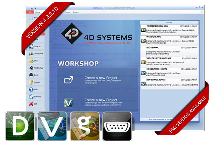
The intelligent gen4 displays can be programmed via Workshop4 IDE. It provides an integrated software development platform for all of the 4D family of processors and modules. The IDE combines the Editor, Compiler, Linker and Downloader to develop complete 4DGL application code.
gen4 modules are available in 4 models:
gen4-uLCD-32D (non Touch, without Cover Lens Bezel)
gen4-uLCD-32DT (Resistive Touch, without Cover Lens Bezel)
gen4-uLCD-32D-CLB (non Touch, Cover Lens Bezel)
gen4-uLCD-32DCT-CLB (Capacitive Touch, with Cover Lens Bezel)
The module is available on the official website with a range of $55 to $79 including interface board, 150mm FFC cable, and a quick start guide. Starter kits are also available from $75 to $99.
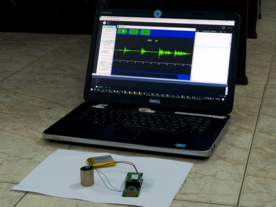
Seismic activity or “Vibrations of the earth” is measured using ProtoCentral’s OpenPressure 24-bit DAQ System.
A geophone is a magnetic device used to measure the Earth’s normal vibrations (some abnormal during events such as earthquakes). These movements are also present when there is a small explosion (commonly used for mining and exploration purposes).
Measuring seismic activity using ProtoCentral OpenPressure – [Link]
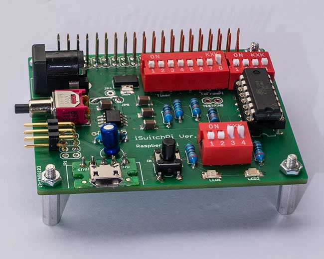
Native Raspberry Pi does not have an On/Off switch and there is no easy way to shutdown the Pi while keeping the filesystem intact. This Intelligent Power Switch allows just that: Power-On the Pi by pressing a pushbutton and also properly Power-Off the Pi with another press on the same button. The intelligence is provided by a program running in an AVR MCU ATtiny44. This C-program implements a Finite State Machine in the MCU. A small Python script is running in the Pi itself. Just one GPIO-Pin is used for two-way communication. In addition, a variable frequency square wave is available for externally interrupting the Pi.
iSwitchPi Adds an Intelligent Power Switch to Your Raspberry Pi – [Link]
Teardown and analysis of microwave (26.5GHz) electro-mechanical step attenuators from The Signal Path:
In this short episode Shahriar takes a close look at a pair of Hewlett Packard microwave electro-mechanical step attenuators operating up to 26.5GHz. Mechanical attenuators offer excellent repeatability, low insertion loss and nearly limitless linearity. The teardown reveals that the construction of both modules is very similar on the microwave path. In fact, the lower-frequency model still uses the same attenuator components. The newer model employs electronic control circuity while the older generation attenuator uses purely mechanically controlled DC path. Both models use a solenoid style actuators for step attenuation control.
Teardown and analysis of microwave (26.5GHz) electro-mechanical step attenuators – [Link]
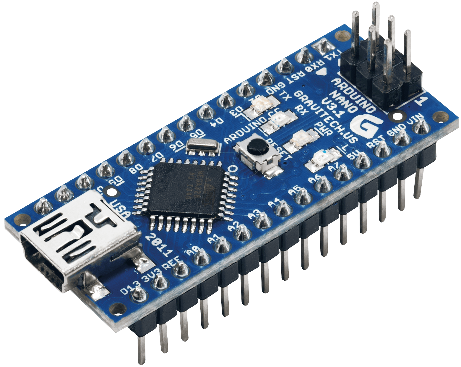
In today’s post, we are going to learn how to make an Arduino nano at home. Electronics enthusiast Pratik Makwana designed this project in instructables.com. Every step in this project is well-explained. If you already don’t know what Arduino Nano is then here is a brief introduction: Arduino Nano is a tiny yet strong member of the Arduino family. It’s powered by an ATMega328P microcontroller running on 16MHz. But, the main strength is its very small form factor.
Arduino Nano
Now, let’s get started and make your own Arduino Nano in no time.
Requirements:
Copper clad board (Double-sided)
Ferric Chloride (FeCl3)
Acetone (Nail polish remover)
Glossy Paper
LASER Printer
Marker Pen
Scissors
Plastic container
Sandpaper
Safety gloves (Optional)
Latex gloves
Saw – For copper board cutting
Laminator or iron
Components of Arduino Nano (Given later)
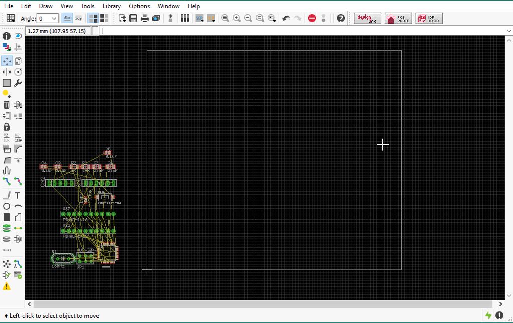
PCB Designing:
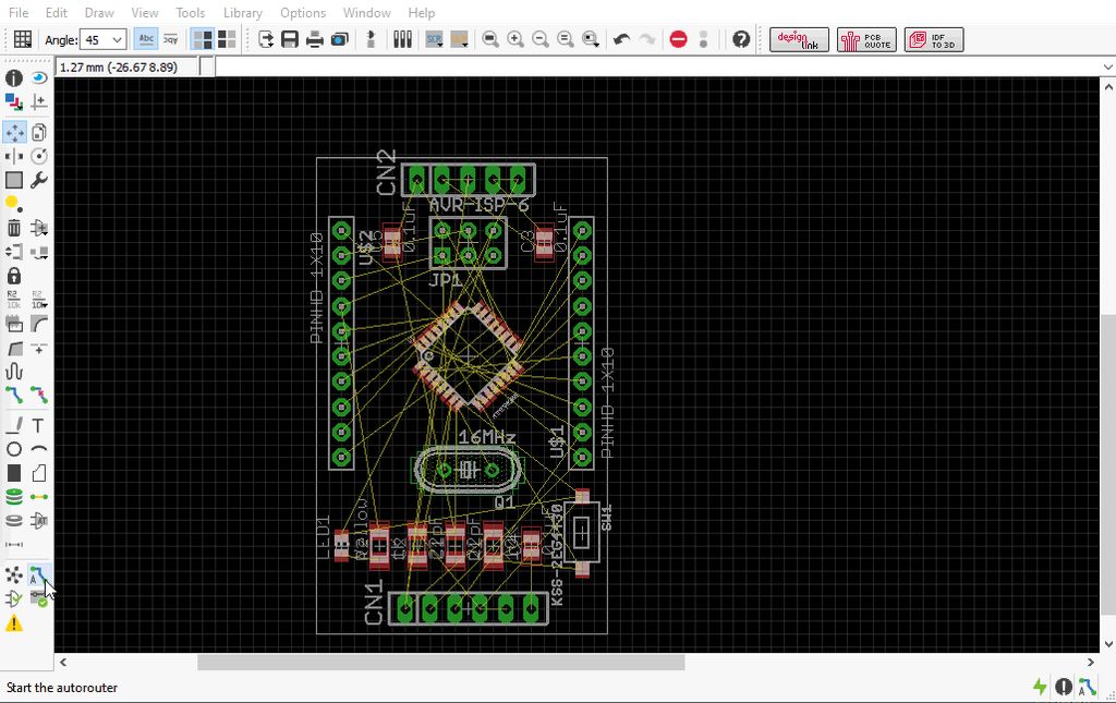
This is a very important step of this tutorial. You need to draw the circuit of Arduino Nano first. Then you’ll design the PCB using the schematic. Design the schematic diagram in an EDA tool (Electronic design automation Software).
Here is a list of EDA Tools:
EAGLE is the most widely used PCB and schematic design software. Though my personal favorite is Proteus. You can use any software from the list.
Importing the Schematic File to PCB Editor
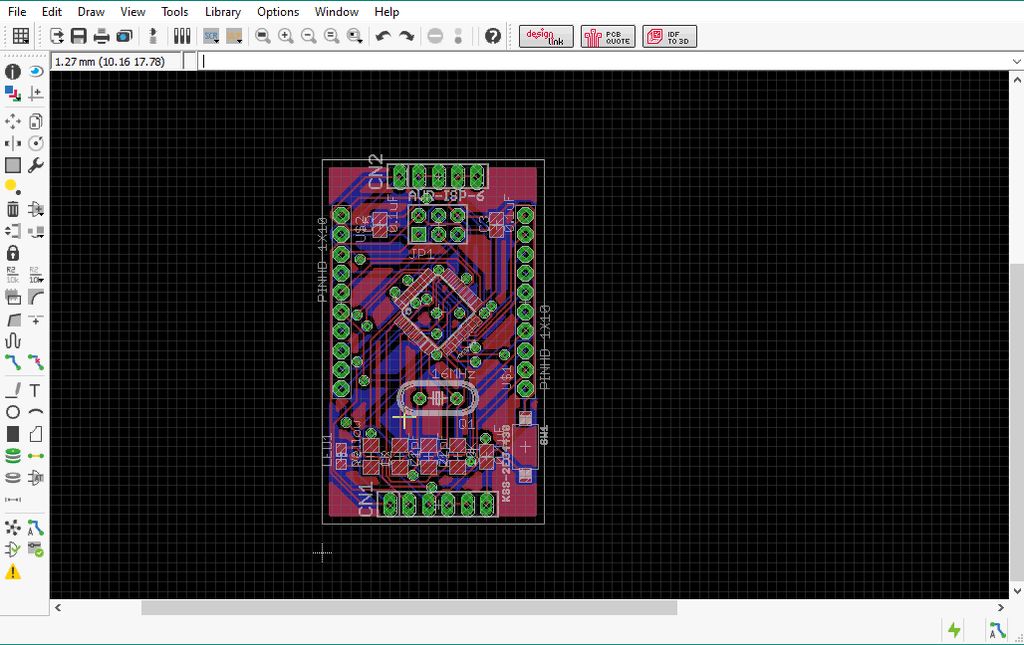
To make the schematic, use the Arduino Nano Circuit Diagram and Arduino Nano Components List. Once it’s drawn completely, open the PCB designing part of the software and you’ll see that schematic is imported there. Now place the components in correct places and connect them using traces. If you are using EAGLE then you can simply download the Arduino Nano Schematic File for EAGLE and Arduino Nano PCB File for EAGLE. Open the .brd file (PCB file) to print the PCB. You can also modify it if you wish.
Place the parts in correct positionConnect the components and the PCB is ready
Note:
Use Only Laser printer only.
Use glossy papers to print.
Set scale factor to 1.
Before top layer printing, you need to mirror the image of the top layer layout.
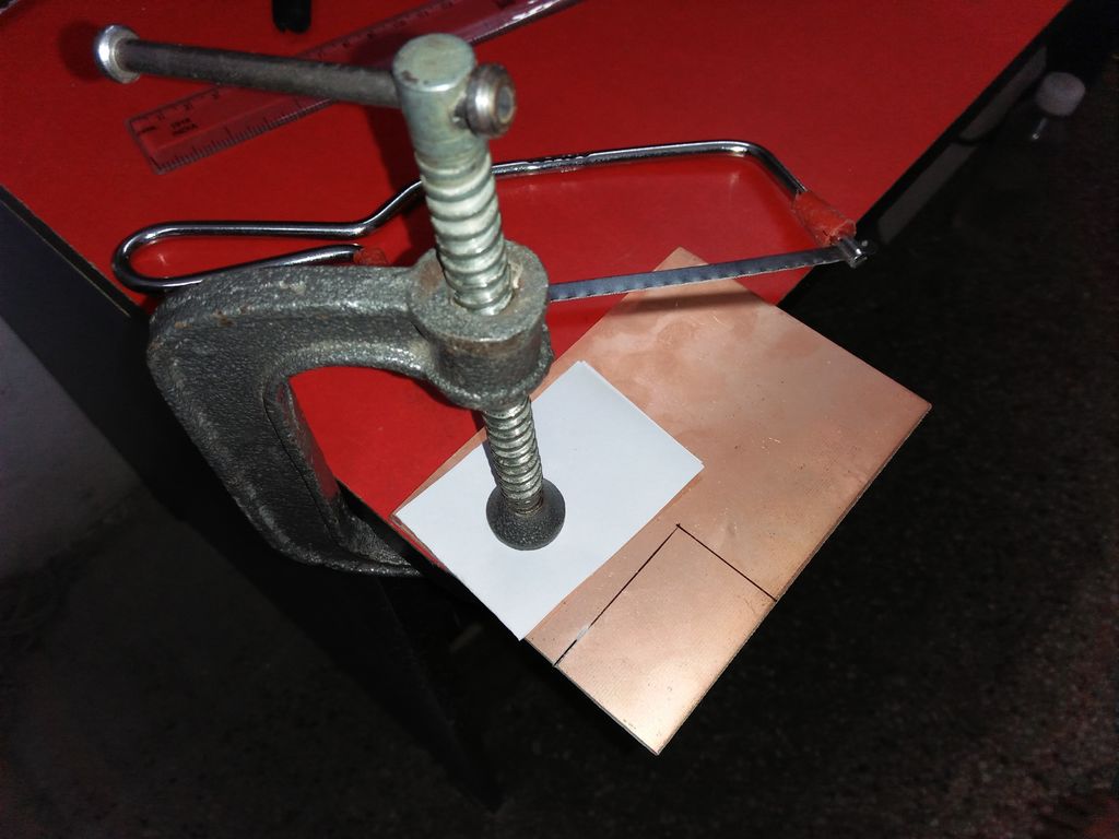
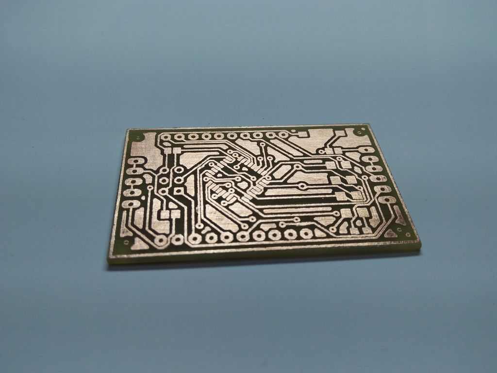
Cut The Copper Clad Board:
Now, cut the copper clad board according to the dimensions of the PCB. You can use a hacksaw to cut it off. Be precise about the dimensions. If it’s smaller than the actual PCB then you have to do it again. Also, cut the printed glossy paper as per the size of PCB.
Cut the copper clad board using a hacksaw
Toner Transfer and Etching Process:
In this step, the PCB design from glossy paper will be transferred to the copper board. All you need to do is place the printed side of the glossy paper on the copper board and apply both pressure and heat. You can use a modified laminator machine or an iron for this purpose. Why “modified”? Because toner transfer method requires a temperature of 210°C, where a laminator can provide 150°C maximum.
Put the board in FeCl3 solution for a while
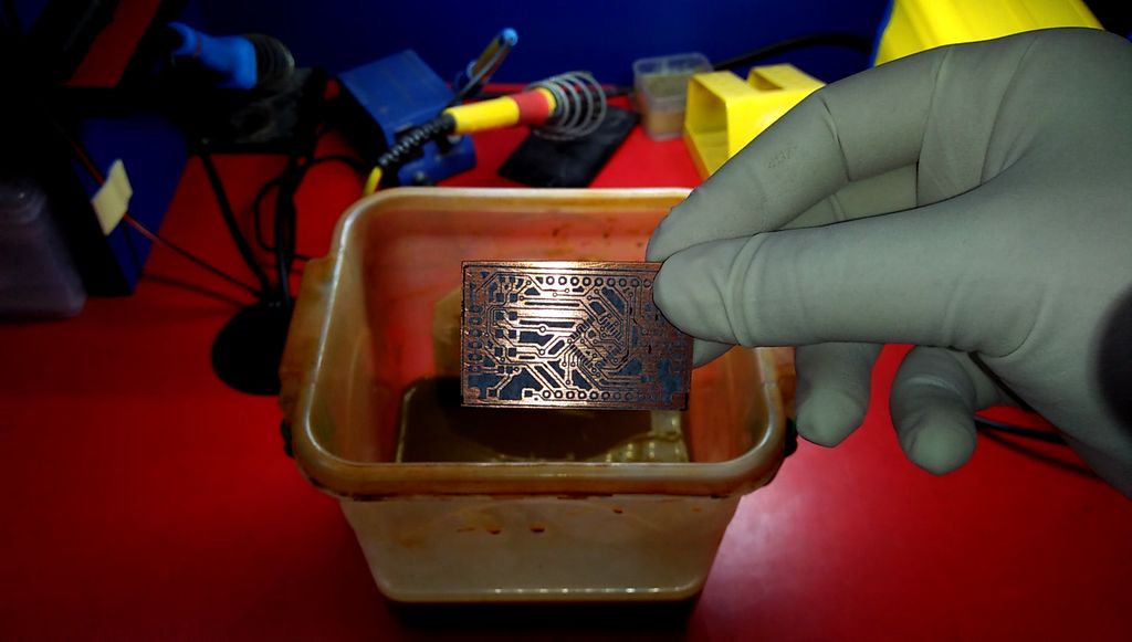
Make your copper clad board as clean as possible beforehand. You can use sandpaper and alcohol to do this. When the toner is transferred successfully, prepare the ferric chloride (FeCl3) solution. Before putting the board into the solution check carefully for any broken path. If found, draw it with a marker. After the etching process, use the acetone to clean the board.
After washing the PCB with Acetone
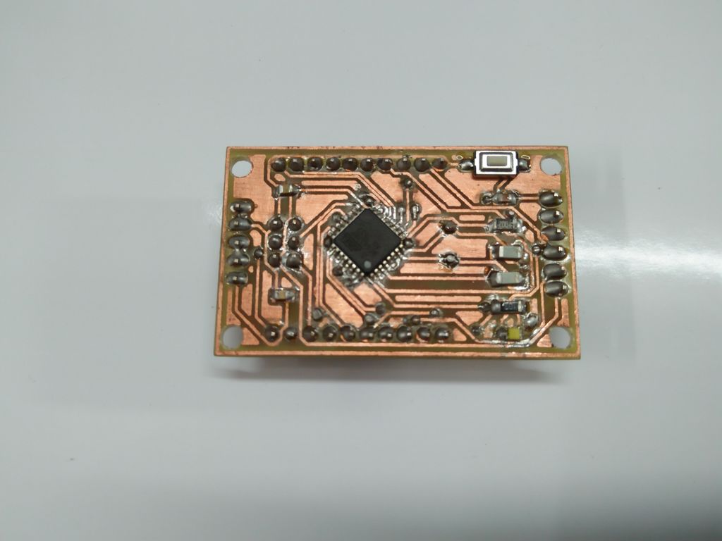
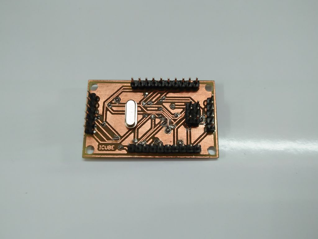
Drilling & Soldering:
Drill the PCB using PCB drill machine. Choose the drill bit wisely else components may not fit. Now, place the components on the PCB and solder them. You can use a helping hand device to get it done nicely.
Upper layer of PCBLower layer of PCB
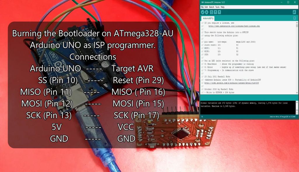
Burning The Arduino Bootloader:
In this step, you’ll need another Arduino board (e.g. Arduino UNO) to burn the bootloader to your newly made Arduino Nano for the first time. Open Arduino IDE and upload the ArduinoISP sketch to the Arduino UNO from examples option. Now, connect your Arduino Nano with Arduino UNO over SPI bus following the given instructions:
Arduino UNO >> Arduino Nano
——————————————-
SS (Pin 10) >> RESET (Pin 29)
MISO (Pin 11) >> MISO (Pin 16)
MOSI (Pin 12) >> MOSI (Pin 15)
SCK (Pin 13) >> SCK (Pin 17)
5V >> VCC
GND >> GND
Follow this instruction to burn bootloader
After making the connections, go to Arduino IDE and follow the given instructions:
Select Tool >> Board >> Arduino Nano
Select Tool >> Port >> Select your Arduino UNO COM Port
Select Tool >> Programmer >> Arduino as ISP
Select Tool >> Burn Bootloader
Wait for the “Done burning bootloader” message to appear.
Testing:
Well, your Arduino Nano is now ready for a test run. This time you won’t need another Arduino to upload codes. Follow the instructions and connect a USB to TTL converter (a.k.a USB to UART converter) with the Arduino nano to upload sketches.
USB to TTL Converter (CP2102) >> Arduino Nano
—————————————————————-
VCC >> VCC
TX >> RX (Pin 30)
RX >> TX (Pin 31)
DTR >> RESET (Pin 29)
GND >> GND
After making the connections, go to Arduino IDE and perform the following tasks:
Select File >> Examples >> 01.Basics >> Blink
Select Tool >> Board >> Arduino Nano
Select Tool >> Port >> Select your Arduino UNO COM Port
Select Tool >> Programmer >> AVRISP MKII
After that, upload Blink Sketch to Arduino Nano and wait for the “Done Uploading” message. LED connected to pin 13 should blink if everything is OK. Now you can upload any sketch you wish to your home made Arduino Nano.
Conclusion:
So, this is how you can make your Arduino Nano. All you need for this project is PCB designing skills and a pretty good soldering skill as you have to deal with SMD components. This way you can make custom Arduino Nano that will fit your project perfectly. Watch the video to have a more clear idea:
In this video, Circuit Basics unbox a new Raspberry Pi B+ and show you the main components on the board. It’s a good primer to watch before you connect it to a monitor, keyboard, or router for the first time.
Explanation of the Components on a Raspberry Pi – [Link]
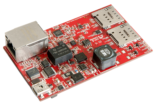
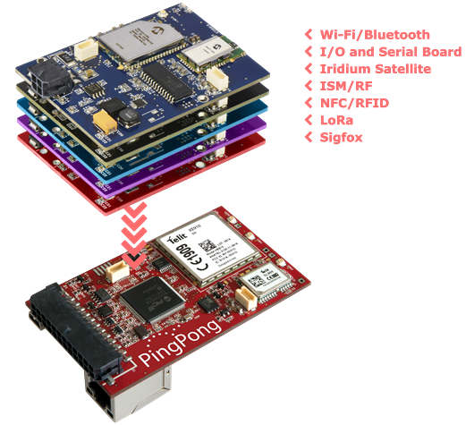
Germany-based Round Solutions developed the PingPong, a powerful and flexible hardware platform for IoT and machine-to-machine (M2M) applications. The PingPong can be used for both wired and wireless connections. The modular hardware design can integrate custom-specific applications and communication standards into a single solution platform that has a very small form factor.
The basic hardware platform of PingPong has a 32-bit 200MHz Microchip PIC32MZ microcontroller unit (MCU) running C/C++ code. It supports RTOS or Real Time Operating System which is available as Open Source Software so that developers can adapt their applications individually and bring them to market more swiftly. The base board of PingPong has following features:
A high-speed cellular module
A component for high-precision Global Navigation Satellite System (GNSS)
An Internet connectivity module
USB
CAN-Bus and many other components
PingPong – The IoT Development Board RTOS 3G Version
One amazing feature is, the high-speed cellular module and the numerous interfaces can be controlled over the cloud. So, you don’t have to keep it wired all the time in order to control all those modules.
Technical Information:
Having an area of 85×52 mm², the PingPong is really tiny in size compared to its features. It has a booming 4 MB flash memory which is perfect for IoT purpose. PingPong beats other IoT modules with the wireless technologies it possesses – 2G, 3G, Galileo E1, GLONASS, and GPS. Supported bands(MHz) for cellular communication are 1800, 1900, 2100, 850, and 900. It communicates with other MCUs over I²C protocol which is widely used by almost all types of MCUs.
The greatest strength of PingPong is its expandability. The developer can overcome all the limitations of PingPong by adding a variety of expansion cards to the PingPong platform. Some examples of expansion cards are, wireless local area network (WLAN), Bluetooth, input/output (I/0), Iridium satellite communications, ISM/RF, SigFox, near-field communication (NFC), radio-frequency identification (RFID), and camera connectivity.
Applications:
Send and receive data: Pingpong offers different possibilities for sending and receiving data. Whether it’s wired over Ethernet or on the go with built-in GSM/GPRS module, PingPong does its job of exchanging data continuously.
Remote control: The PingPong can be used to control processes remotely via its outputs. Using the digital output with a relay can either enable or disable the power supply of an application.
Positioning: With its built-in GNSS and GPS module, the PingPong can also be used to determine position, motion, speed and acceleration.
Telemetry: The PingPong can be connected to a wide variety of sensors to process digital and analog measurements. Thus, for example, temperature values collected from a temperature sensor can be transferred via analog input to the PingPong.
And there are much more applications. From hobby projects to industrial development, sensor data collection to the smart home project – anywhere you can use this versatile board.
To learn more on this amazing IoT board, watch these three videos:
Conclusion:
The PingPong is a surprisingly powerful IoT module. It’s a developer’s dream. Having all these features in one package is truly outstanding. The feature of adding expansion cards makes it even stronger.
You can purchase your own PingPong from roundsolutions.comat €199.00. It may seem to be a bit overpriced, but it’s really not. Just consider the features you are getting in a single package and you’ll realize it.
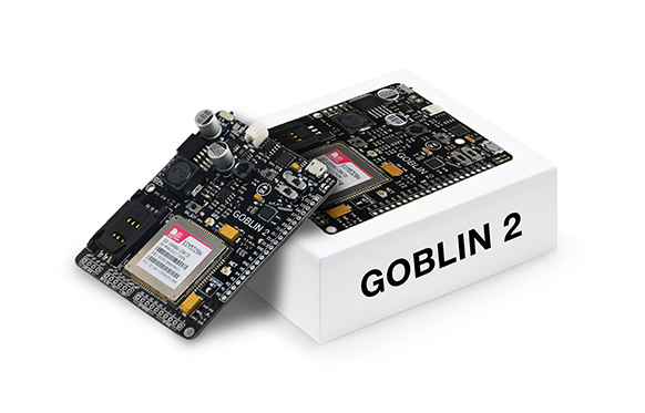
Designed for industry, makers, and visionary students, Verse Technology presents GOBLIN 2, its new card with the best of Arduino technology.
GOBLIN 2 is an IoT development board that unlocks the potential of the Internet of Things. It has been built based on the high-performance 16MHz ATmega328P microcontroller with a built-in SIM5320A connectivity module, and high accuracy 16-channel GPS.
The board contains 10 digital I/O ports half of them work as PWM, and 6 analog pins. It also integrates connectivity for each RS-485 protocol and voltage outputs of 24V, 5V and 3.3V that are ideal for industrial sensors or sensors with analog/digital signal.
The SIM5320A incorporates a dual-band HSDPA/WCDMA and Quad-Band GSM/GPRS/EDGE which gives GOBLIN 2 the connectivity with web servers through any cellular web. It also includes inlets/outlets to connect peripherals like keyboards, microphones, speakers, and thus exploit better the cellular network.
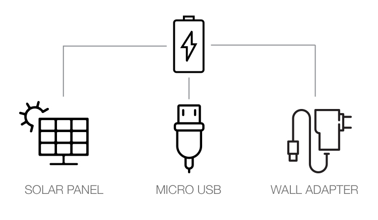
External Power Input: Micro USB 2.0 5V, Solar Panel 5V up to 200mA, 3.7V battery charger.
Power Output: 3.3V 300mA, 5V 3A, 24V 500mA.
Ports:
6 ADC input – 10 bits resolution
10 digital in/out – 5 PWM
1 Micro USB Up to 115.2k baud
Connectivity:
SIM5320A with Header USB 2.0 interface
Header to Keypad, microphone and speaker for SIM I/O
High accuracy 16 channel GPS
RS-485 protocol 10Mbps Up to 256 nodes on the bus
GOBLIN 2 is powered by Li-Po battery of 3.7V to 4.2V, which can be charged through a solar cell or a Micro-USB thanks to its built-in battery management module. With an integrated voltage converter, GOBLIN can offer three output voltages; 24V to industrial sensors, 5v to charges like servomotors or related sensors with that kind of supply voltage and 3.3v for communication devices such a RF, Wi-Fi, sensors and others.
The board’s microcontroller can be programmed with Arduino IDE or Atmel Studio via micro USB, which also can be used for direct communication with the SIM5320A from the PC for a SIMCOM “AT+” command interchange.
Some of GOBLIN 2 applications:
Monitoring of industrial sensors with an RS-485 protocol.