How to Write and Run a C Program on the Raspberry Pi

In this tutorial, circuitbasics.com discuss what a C program is, what C programming is used for, and finally, how to write and run a C program on the Raspberry Pi.

The C programming language is one of the most widely used programming languages of all time. It is computationally faster and more powerful than Python. C is a middle level programming language because of its low level of abstraction to assembly language.

How to Write and Run a C Program on the Raspberry Pi – [Link]

Weather Station with a BME280 sensor and an LCD screen with Arduino Mega

In this Arduino Project video educ8s.tv is going to build a simple weather station using a BME280 sensor and an LCD shield.

Hello guys, I am Nick and welcome to educ8s.tv a channel that is all about DIY electronics projects with Arduino, Raspberry Pi, ESP8266 and other popular boards. Today we are going to take a first look at the new BME280 sensor, a new very interesting sensor. We are going to build a simple but very accurate weather station project. I have built a similar project 2 years ago, using different sensors. Now that we have a new sensor available which makes things easier, it’s time to update the project. As you can see, on the LCD display we can see the temperature, the humidity and the barometric pressure. The readings are updated every two seconds. This is a very easy project to build so it is ideal for beginners! Let’s build it!

Weather Station with a BME280 sensor and an LCD screen with Arduino Mega [Link]

DS28EC20, A Serial 1-Wire 20Kb EEPROM

The American manufacturer of analog and mixed-signal integrated circuits, Maxim Integrated, has developed a new serial EEPROM memory that operates from single-contact 1-wire interface.

The DS28EC20 is a 20480-bit, 1-Wire® EEPROM organized as 80 memory pages of 256 bits each. An additional page is set aside for control functions. Data is written to a 32-byte scratchpad, verified, and then copied to the EEPROM memory.

The 1-Wire is a device communications bus system that provides low-speed data, signaling, and power over a single conductor. This technology uses only two wires; data and ground. It is similar in concept to I²C, but with lower data rates and longer range. It is typically used to communicate with small inexpensive devices such as digital thermometers and weather instruments.

DS28EC20 features:
  • 20480 Bits of Nonvolatile (NV) EEPROM Partitioned into Eighty 256-Bit Pages
  • Individual 8-Page Groups of Memory Pages (Blocks) can be Permanently Write Protected or Put in OTP EPROM-Emulation Mode (“Write to 0”)
  • Read and Write Access Highly Backward-Compatible to Legacy Devices (e.g., DS2433)
  • 256-Bit Scratchpad with Strict Read/Write Protocols Ensures Integrity of Data Transfer
  • 200k Write/Erase Cycle Endurance at +25°C
  • Unique Factory-Programmed 64-Bit Registration Number Ensures Error-Free Device Selection and Absolute Part Identity
  • Switchpoint Hysteresis and Filtering to Optimize Performance in the Presence of Noise
  • Communicates to Host at 15.4kbps or 90kbps Using 1-Wire Protocol
  • Low-Cost TO-92 Package
  • Operating Range: 5V ±5%, -40°C to +85°C
  • IEC 1000-4-2 Level 4 ESD Protection (8kV Contact, 15kV Air, Typical) for I/O Pin

Blocks of eight memory pages can be write-protected or put in EPROM-Emulation mode, where bits can only be changed from a 1 to a 0 state. The life-expectancy of the DS28EC20 is specified at more that 200 k erase/write cycles at 25 °C. The I/O pin has IEC 1000-4-2 Level 4 ESD protections (8 kV contact, 15 kV air).

Applications that can use the DS28EC20:
  • Card/Module Identification in Rack-Based Systems
  • Device Authentication
  • IEEE 1451.4 Sensors
  • Ink and Toner Cartridge ID
  • Medical and Industrial Sensor Identification/Calibration
  • PCB Identification
  • Smart Cable

Ordering DS28EC20 is available for about $1.7 per chip through Maxim website. You can also get design resources and technical documents of the chip.

How to Read Your First Autodesk EAGLE Schematic

Back to basics. Here is a tutorial on autodesk.com blog on how to read schematics:

The schematic forms the building block of every electrical circuit, and even if you aren’t designing one yourself, knowing how to read one is invaluable. And with some schematic reading knowledge in hand, you’ll be able to design, build and ultimately troubleshoot your way through your design logic before heading on to your PCB layout.

How to Read Your First Autodesk EAGLE Schematic – [Link]

How to Set Up and Program an LCD Display on an Arduino

circuitbasics.com has a tutorial on how to setup an LCD with Arduino.

In this tutorial, I’ll explain how to set up an LCD display on an Arduino, and show you all the functions available to program it (with examples). The display I’m using here is a 16×2 LCD display that I bought for under $10 on Amazon. LCDs are really useful in projects that output data, and they can make your project a lot more interesting and interactive.

How to Set Up and Program an LCD Display on an Arduino – [Link]

HPS140MK2, The New Handheld Oscilloscope

Velleman Inc., a producer and a distributor of electronics, has produced a new handheld oscilloscope with the same power of its HPS140, but with smaller size and modern design.

HPS140MK2 is a 11.4 x 6.8 x 2.2 cm versatile component tester that fits in your pocket. This small oscilloscope features a real time 40 MS/s sampling rate with up to 10 MHz bandwidth and 0.1 mV sensitivity.

HPS140MK2 features:

  • 40 Mega samples/sec in real time
  • Bandwidth up to 10 MHz
  • Full auto range option
  • Sensitivity down to 0.1 mV
  • Signal markers for amplitude and time
  • Memory hold function
  • Direct audio power measurement

The device is powered by 4 AAA batteries. On the front panel you can find four buttons; menu, up, down, and hold. The display is used to menu options and received signal. On the top side you will find an on/off switch and a BNC input connector that can accept maximum input of 100Vp.On the bottom side there is an X10 probe test signal.

Specifications:

  • Bandwidth: up to 10 MHz (-3dB or -4dB at selected ranges)
  • Input range: 1 mV to 20 V / division in 14 steps
  • Input coupling: DC, AC and GND
  • Real-time sample rate up to 40 MS/s
  • AD resolution: 8 bits
  • Time base: 250 ns to 1 h per division
  • Auto set-up function (or manual)
  • Probe x10 readout option
  • Readouts: DC, AC + DC,True RMS, dBm, Vpp, Min-Max. (±2.5%)
  • Audio power measurement from 2 to 32 ohms
  • Hold & store function
  • Time and voltage markers readout
  • Max. 100 Vp AC + DC
  • Monochrome OLED
  • Power supply: 4 x 1.5 V AAA batteries (not incl.)
  • Operating time: up to 8 hours on quality Alkaline batteries
  • Dimensions: 114 x 68 x 22 mm
  • Weight: 166 gr
  • Current consumption: max. 150 mA

The product is available for $150 on Velleman store. Additional parts will be available soon including component tester ‘HPS141’ to receive all useful information about resistors, transistors, diodes and more, including their pin out identification, and the ‘HPSP1’ protective pouch.

DIY Arduino-Based Desktop CNC Router

Inspired by machines like the Nomad 883 from Carbide3D, Carvey from Inventables and more, Thimo Voorwinden had come up with a new tutorial for building a desktop CNC router powered by Arduino.

This CNC budget is around €200 and you don’t need a workshop to build it up, basic tools will do. It is designed to be modular, Arduino powered, and with a tolerance of (±0,1 mm). It has Ø8 mm linear rods, M8 thread lead screw and uses NEMA 17 stepper motors and drv8825 drivers. Plus, 250 watt flexible shaft is needed to drive the spindle and it has a work area of 200 x 250 x 100 mm (x,y,z).

Here you are the Bill of Materials that Thimo made based on his research in German and Chinese web-shops:

The tools Thimo used to build this CNC are listed here:

  • Homemade router table
  • Old ‘cordless’ drill
  • Ø22 mm wood spade drill
  • A rusty collection of old metal drill bits
  • Hammer
  • Metal saw
  • File
  • Screw drivers
  • Clamps
  • Try square
  • A soldering iron

Thimo shared this experience as a 5 HD video tutorials on Youtube to explain all the steps he went through: setting X and Y axis, the frame, Z axis and spindle, electronics and a video where the CNC is in action while milling a jigsaw piece. He added two extra videos for foam milling and testing the plotting function. Check them out here:

“For about €200 I’m now capable to CNC machine wooden parts. Not at a high speed, or without any bumps along the way, but having this option is still great. I will definitely try to machine some gears, specific parts for projects and engrave signs with this in the future.”

For more information, a detailed guide, and some notes check the project’s page at Thimo website.

Make Your Own Laser Scanning Microscope

A laser scanning microscope (LSM) is an optical imaging technique for increasing optical resolution and contrast of micrographs. It permits a wide range of qualitative and quantitative measurements on difficult samples, including topography mapping, extended depth of focus, and 3D visualization.

A laser microscope works by shining a beam of light on a subject in an X-Y plane. The intensity of the reflected light is then detected by a photoresistor (LDR) and recorded. When the various points of light are combined, you get an image.

Venkes had built his own DIY laser scanning microscope with a DVD pick-up, an Arduino Uno, a laser, and a LDR. He had also published an A-Z tutorial about making a similar device.

The result image consists of 256×256 pixels with resolution of 200 nm, about 1300 time enlargement, and it will not cost you a lot because you may have most of the parts. However, the scanning process is a bit slow, it may need half an hour for one image, and it is not crispy sharp.

The parts needed for this DIT LSM are:

  • 2 lens/coil parts of a laser pick-up (DVD and/or CD)
  • a bit of PCB
  • a piece if UTP cable (approx 15cm)
  • An Arduino UNO
  • An LDR
  • 2 x 10uF capacitors
  • 1 x 220 Ohm resistor
  • 1 x 10k resistor
  • 1 x 10k pot
  • 1 x 200 Ohm trim potentiometer
  • 1 breadboard
  • 1 switch
  • 1 3,5 mm jack plug
  • 1 audio amplifier
  • 1 laser with a good collimating lens
  • 1 piece of glass, a quarter of a microscope object glass or so to act as a semipermeable mirror
  • The under part of a ballpoint casing to put the LDR in

For the software side, an Arduino sketch is used to steer the lens, to read the LDR values, and to send information to a Processing sketch which will receive the data and translate it into an image.

You can find more details of this project with the source files at the project’s Instructables page. This video shows the device in action:

5V to 12V @1.2A regulated power supply using LM2587

This circuit is based on LM2587, a simple boost converter from Texas instruments. It produces a 12V regulated output for a input of 5V. It can also be used as a multiple output regulator, forward converter and as a flyback regulator. This regulator requires minimum number of external components, which makes it cost effective.

Features

  • Input(V): 4.5VDC to 5.5VDC
  • Output(V): 12V DC
  • Output load: 1.2A
  • PCB:38mm X 30mm

5V to 12V @1.2A regulated power supply using LM2587 – [Link]

Send Touch Over Distance With HEY Bracelet

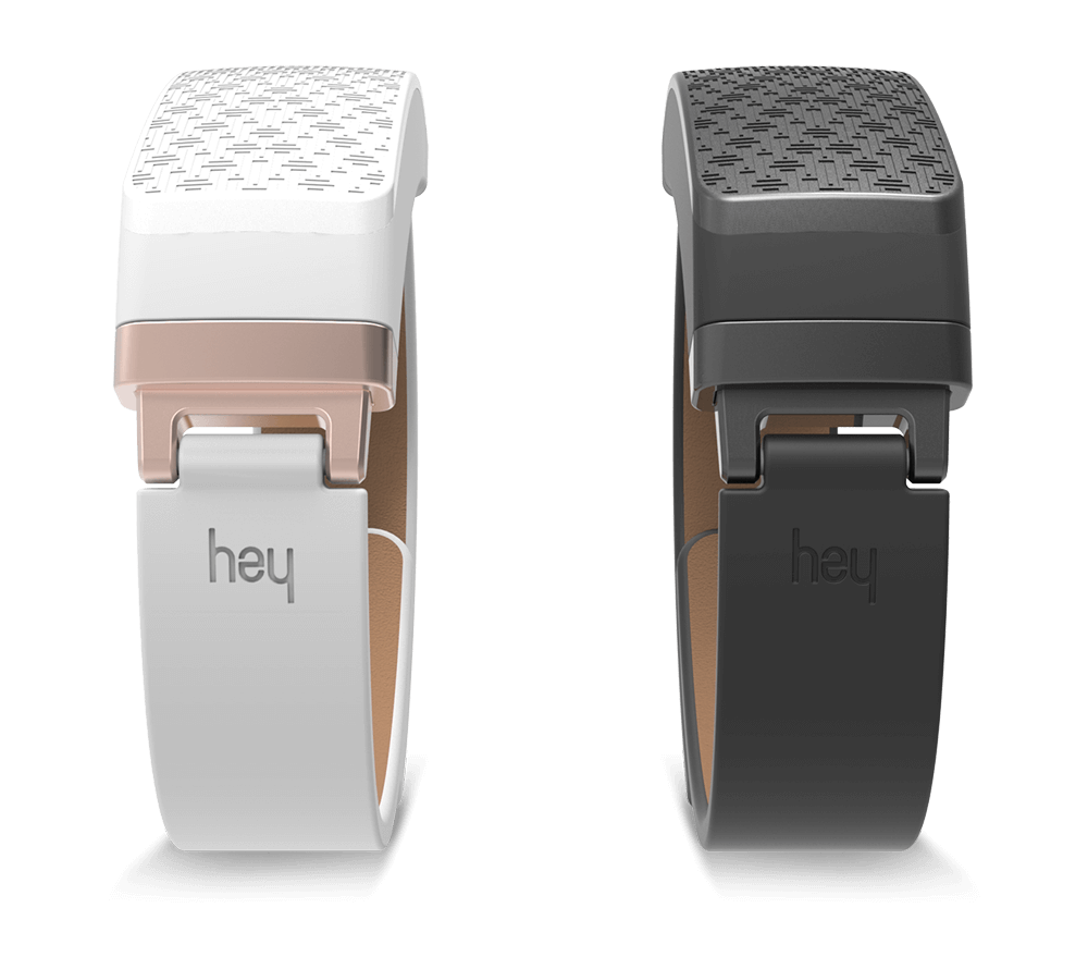
HEY is an innovative bracelet that really makes you feel connected to a loved one. It uses a unique technology to send your touch as far as needed. It’s the first bracelet that mimics a real human touch, not by producing a mechanical vibration or buzzing sensation, but an actual gentle squeeze.

On Valentine’s Day the stylish piece of smart jewelry was launched on Kickstarter and within one hour it was already ‘trending’. Check the campaign video:

The bracelet incorporates advanced technology that communicates through Bluetooth with your smartphone. The ingenious design  ensures that a touch wouldn’t be sent accidentally. In order to send a message you should touch the bracelet in two places and it will be transferred directly to your phone and from there to the connected HEY bracelet anywhere in the world.
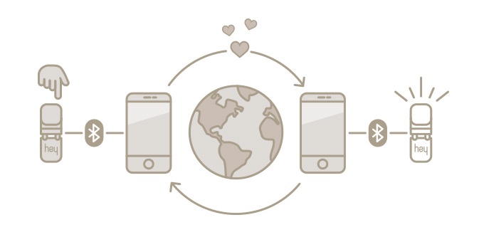
Via Bluetooth HEY is connected to an app on your smartphone. This app makes sure all your little squeezes reach the other bracelet directly. It also helps you pair the bracelets easily, fast and without any hassle. And last but not least it keeps track of your love stats. For instance the distance between you and your loved one or the last time you were together. If desired, these features can be turned off. In the future more features will be added to the app.

HEY is invented by Mark van Rossem. He looked at the current world of communication and saw that one thing was missing. And that thing was touch. People communicate through technology 24/7, but there is always a physical distance separating them. So Mark set himself the seemingly impossible goal to send touch at great distances and came up with the idea for HEY. Together with successful entrepreneur, David van Brakel, he gathered a team of creative and technical professionals that have all earned their credentials in their field of expertise. Together they want to build products that bring people closer.

“From a simple touch like squeezing someone’s hand, to hugging, social touch is important in the way we maintain healthy and happy social relationships with the people that we care about most.” – Gijs Huisman, who collaborated in developing bracelet, is an expert at the University of Twente in the field of Social Touch Technology and has been researching haptic technology (touch by tech) for five years now.

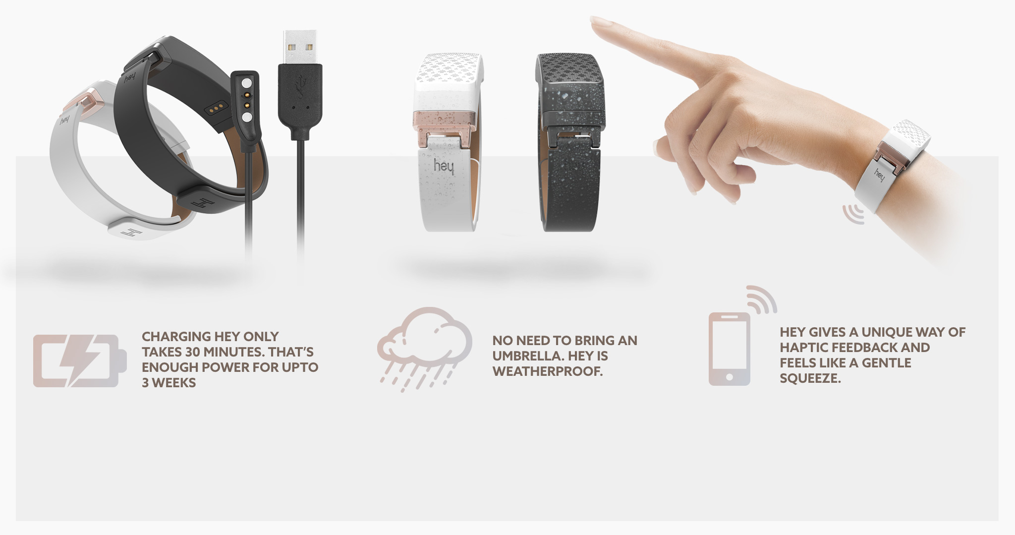
No need to worry a lot about the safety of the bracelet electronics since the design is weatherproof. With only 30 minutes of charging, you will be able to send touches for around 3 weeks!

HEY adds a completely new dimension to relationships and more haptic products will be developed in the near future. For more information and updates, check the official website and the Kickstarter campaign. 35 days are left to pre-order 2 HEY bracelets with the Kickstarter deal for €83 which is 30% of the retail price.

TOP PCB Companies