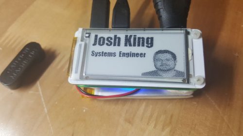
Maker Josh King has introduced the PiE-Ink Name Badge.
Introducing the PiE-Ink Name Badge – a Raspberry Pi Zero Python Powered E-Ink Linux Name Badge (what a mouthful!). A full wearable linux computer system on your chest!
We covered 4Duino in one of our previous blog posts. 4Duino is a 2.4” Arduino based programmable display module. In our article today, we are presenting a hands-on experience with this product by building a simple project. Many thanks to 4D Systems for sending us a sample and giving us a chance to try this new product.
4Duino – An Introduction and a Weather API Demo – [Link]
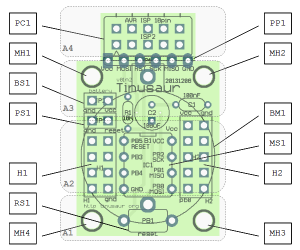
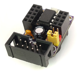
Tinusaur is an Atmel ATtiny85 microcontroller board that comes in parts, as a kit, so you can solder it yourself and then program it. This small microcontroller board can run Arduino and its goal is to have a simple, cheap and quick-start platform for everyone interested in learning and creating things.
Tinusaur comes as an assembly kit, in parts, all in a small plastic bag, so you have to solder it yourself. In order to program this microcontroller board you will need a programmer like AVR ISP programmer, you can also use an Arduino to program the ATtiny microcontroller.
These are the components of Tinusaur standard kit:
PCB: Tinusaur PCB
MCU, Attiny85: Atmel AVR ATtiny85 microcontroller
Socket, DIP-8: DIP-8 socket for MCU
H1, Header: Header 2×4, Female
H2, Header: Header 2×5, Female
ISP, Header: Header 2×5, Male, for ISP
RESET, Button: Tactile push button, for RESET
Power, Header: Header 1×2, Male, for external power
Battery, Header: Header 1×2, Male, for battery power on/off
Battery, Jumper: Jumper, 2-pin, for battery power on/off
C1, Capacitor: Capacitor 100uF, Low profile 5×5 mm
C2, Capacitor: Capacitor 100nF, Small
R1, Resistor: Resistor 10K, Small, 1/8W
Battery holder: Battery holder for CR2032
Battery 3V: Battery 3V, CR2032
There is also the Tinusaur Starter – another kit that has everything included in the Tinusaur Board plus a USBasp programmer, plus few other useful things.
Tinusaur was launched 3 years ago and it is now used in schools and universities to educate young people in both hardware and software. The team behind Tinusaur had launched an Indiegogo campaign to produce more of Tinusaur boards and bring the cost down to $3 per basic board and allow more people to be able to get them. A recent crowdfunding campaign was held by the team, it didn’t meet its goal plus it had the price multiplied by 3!
With just $3 you can get now the Lite edition of Tinusaur, the same components as the standard kit excluding the battery and its holder. You can get the Standard one for $4 and the Starter one for $6.
A dot matrix RGB LED graphic panel, managed by a FPGA-based controller board that may be separately used as a demoboard, so to evaluate the potential of the on-board Spartan 6. First installment.
A FPGA controlled RGB LED MATRIX for Incredible Effects – [Link]
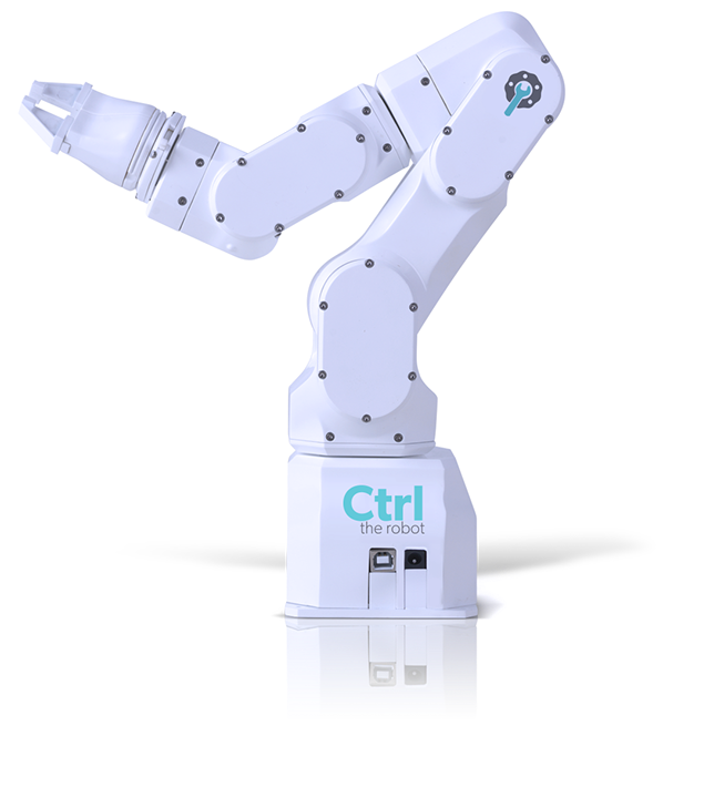
CTRL the robot is a desktop-sized robot arm that can do a lot! It enables your computer to perform manipulation of real objects via software and gives you access to technology that has been locked away in large corporations factories.
Check this video to see the amazing features of CTRL.
CTRL was launched on a Kickstarter campaign that unfortunately didn’t reach its goal of AU$ 215,000. The early bird product was sold for AU$ 699 (~ $540) and you were able to get two robots for AU$ 1598 (~ $1230).This robot arm is a fraction of the price of similar robots you might see in factories. It was developed by Robotics Evolved to be an affordable robot arm.
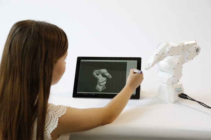
Unveiled at CES 2017, this desktop-sized robot arm aims to make robotics more accessible to the masses. The device is open-source and can be run on the programming language of the user’s choosing. For those unfamiliar with code, CTRL can also learn to replicate movements when manipulated by hand.It ships with example applications with source code and ‘Motion CTRL Studio’ software to easily run diagnostics, visualise movements and script interactively.
CTRL is equipped with a gripping tool but the company plans to expand attachment offerings to include options like spray nozzles and engraving tools. Also in the box is a gripping tool, with a range of interchangeable arm tools to follow including suction pads, spray nozzles, laser engraving tools and more. The team has also made this technology open-source, themechanical, electronic and firmware source, so users can invent their own tools and 3D print them.
With a full range of movement through 6 axis articulation, CTRL the Robot can lift and carry with incredible precision. It uses specially designed brushless servo motors for smooth motion. Even though it roughly stands at the height of a piece of A4 paper, it can reach as far as a human arm and carry up to 1.7 pounds (750 grams). The team used a custom cycloid gearbox design with a pass-through encoder that was conceived, designed and prototyped. The gearbox is highly efficient and can be back driven. It has multiple contact points and offers zero backlash.
Robotics Evolved was seeking funding through a Kickstarter campaign and maybe they should now find another way to bring this product to life again. You can sign up on their newsletter to keep updated with the next steps for CTRL!
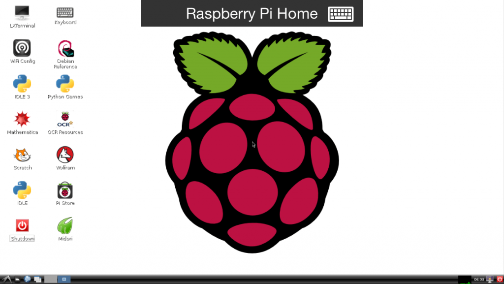
circuitbasics.com has a tutorial on how to access Raspberry Pi with a remote desktop connection.
In the previous post, we learned how to set up a WiFi dongle and access the Raspbian command prompt via an SSH client called PuTTY. PuTTY is a great application for accessing the command line in Raspbian from another computer, but you can’t use it to access the Raspbian desktop (GUI). In order to access the Raspbian GUI from another computer, we need to configure it to work with a remote desktop application. This will allow us to access our Raspberry Pi desktop (or the command line) from anywhere in the world as long as we have a computer with an internet connection.
How to Access the Raspberry Pi GUI with a Remote Desktop Connection – [Link]
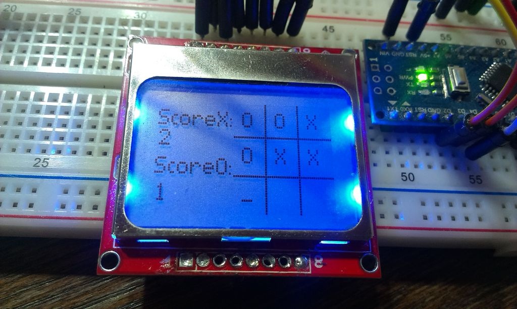
In this Arduino project video educ8s.tv is going to build an Arduino Game, a Tic Tac Toe game with a touchscreen.
In this video we are going to build an Arduino Tic Tac Toe game. As you can see, we are using a touch screen and we are playing against the computer. A simple game like Tic Tac Toe is is a great introduction to game programming and Artificial Intelligence. Even though we won’t be using any Artificial Intelligence Algorithms in this game, we will understand why Artificial Intelligence Algorithms are required in more complex games.
Tic Tac Toe Game with a touch screen and an Arduino Uno – [Link]
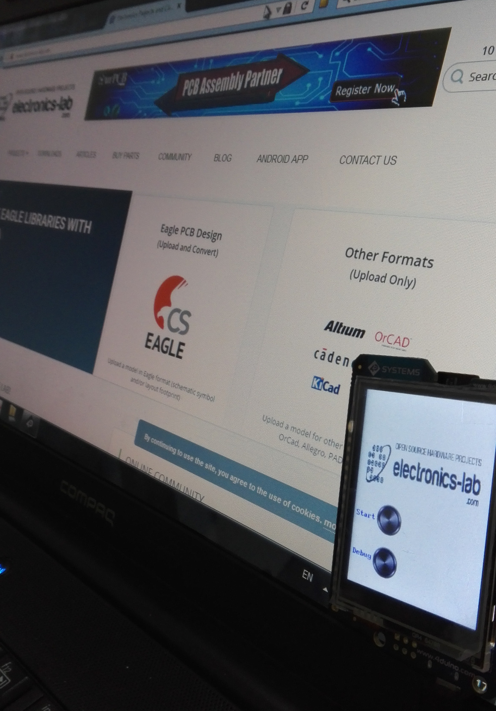
We covered 4Duino in one of our previous blog posts. 4Duino is a 2.4” Arduino based programmable display module. In our article today, we are presenting a hands-on experience with this product by building a simple project. Many thanks to 4D Systems for sending us a sample and giving us a chance to try this new product.
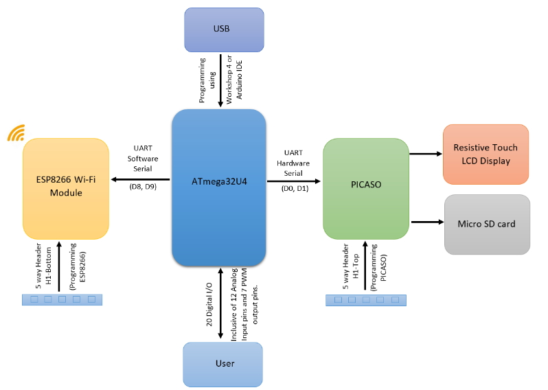
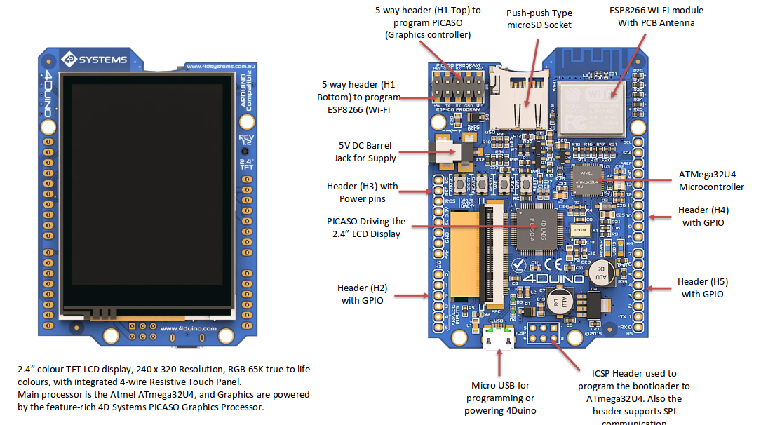
Let us start by making a simple circuit design overview. 4Duino consists of three main parts:
The main MCU is ATmega32U4 which is the same microcontroller inside Arduino Leonardo. 4Duino also preserves Arduino UNO pinouts using the same Arduino’s headers footprint.
An ESP8266 WiFi module ESP-06 model is embedded in 4Duino making it suitable for IoT (Internet of Things) applications.
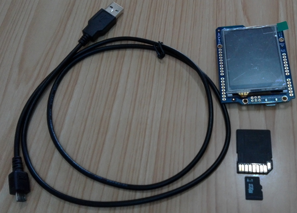
4Duino features a 2.4” 320 x 240 pixels 65K colors TFT LCD display with resistive touch. LCD is powered by the feature-rich 4D Systems Picaso Graphics Processor connected also with an SD card socket.
You can program the main MCU (ATmega32U4) via USB using Arduino IDE after adding 4Duino in the IDE from the “Boards Manager” as we’re going to see in this intro.
4D Systems Picaso Graphics Processor and ESP8266 WiFi modules both use UART to interface with Atmega32U4, but there is only one available UART interface in this MCU. So 4Duino uses the embedded UART peripheral in the MCU to interface with Picaso and a software emulator for UART to interface with ESP8266, this technique is regularly known as Software Serial.
The 4Duino datasheet clarifies this point as follows:
D0 (RX), D1 (TX) are already occupied in order to communicate to PICASO via Hardware Serial. Hence, those pins are not available if communication between PICASO and ATmega32U4 is required. Similarly, D8 and D9 are occupied in order to communicate to ESP8266 via Software Serial. As a result, those pins are not available if communication between Wi-Fi module and ATmega32u4 is required. The ESP8266 could be held in reset to utilise these pins for other purposes.
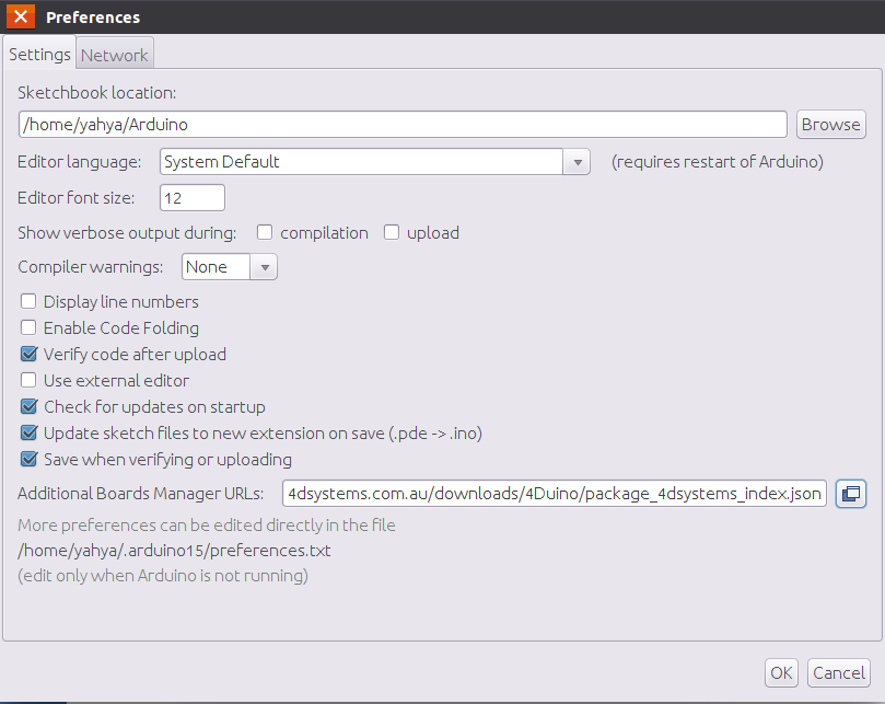
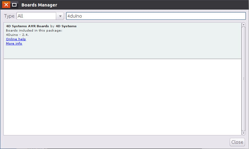
To use Arduino IDE we need to add 4Duino from the Boards Manager. From File > preferences, add the following URL in the “Additional Boards Manager URLs” field.
Now you should be able to see 4D Systems package in tools>board>board manager.
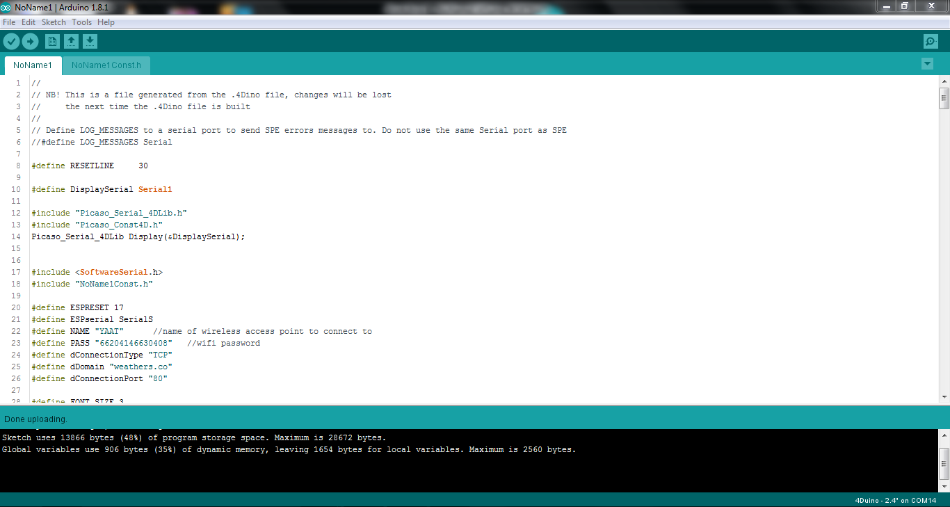
You can see the demo project compiled using Arduino IDE on the screenshot below :
As we said, 4D Systems’s Workshop IDE is another option to develop 4Duino projects, but you can’t compile and upload 4Duino sketches without installing Arduino IDE on your machine, because Workshop uses Arduino IDE tools (AVR GCC and AVRdude) to compile and upload the code.
Downloading and installing Workshop and 4Duino drivers from 4D Systems website is straightforward. Now let’s explore Workshop environment.
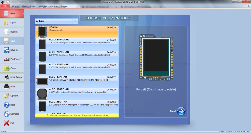
First you select your product:
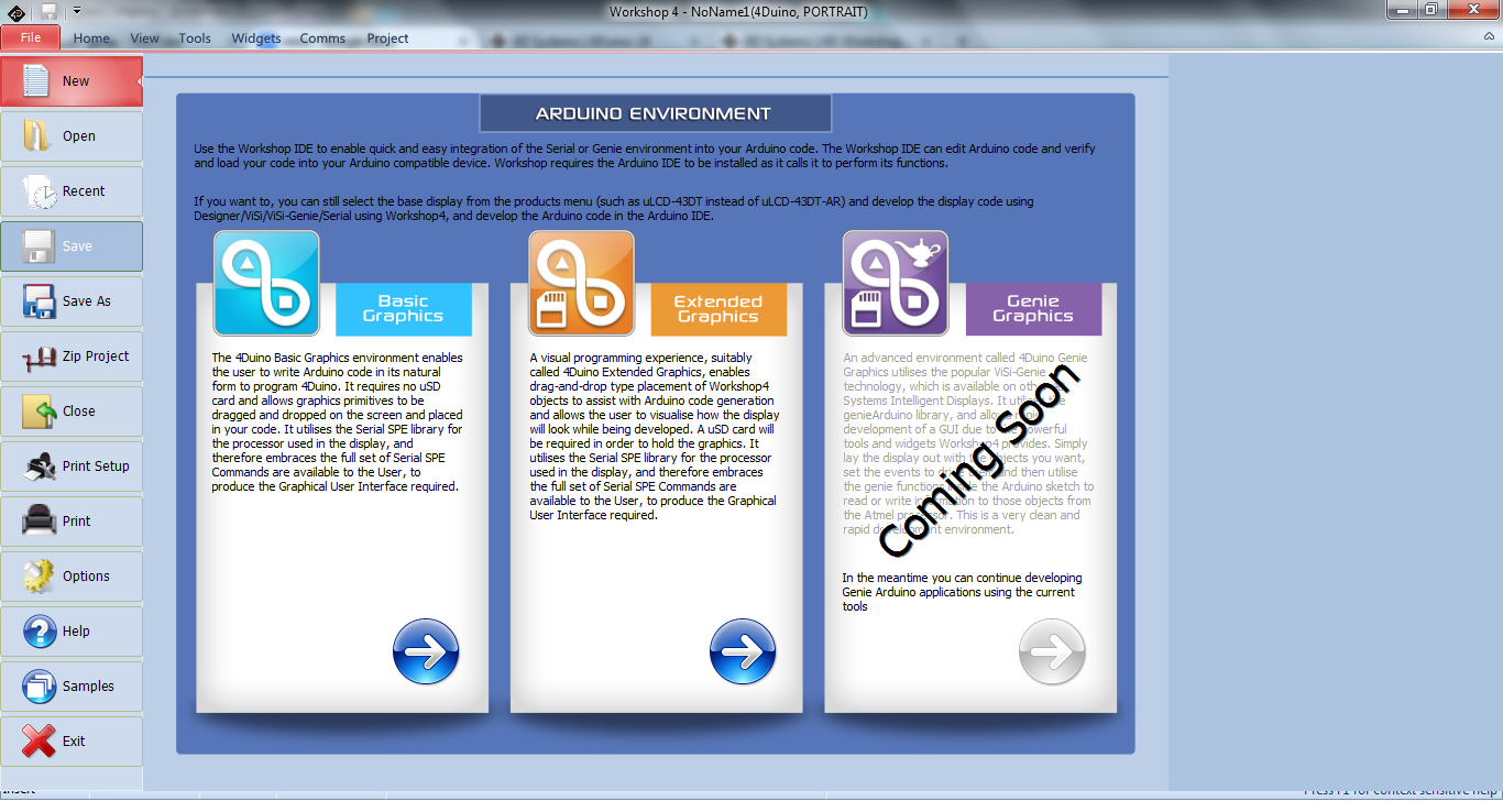
Then you need to choose between 2 types of projects (in the future you would be able to choose between 3):
Basic Graphics, enables the user to write Arduino code with basic widgets. It requires no uSD card and allows graphics primitives to be dragged and dropped on the screen and placed in your code. It utilizes the Picaso Serial library, and therefore embraces the full set of Picaso Serial SPE Commands and make them available to the user.
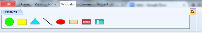
Basic Graphics Widgets Menu
Extended Graphics, enables the user to write Arduino code with extended widgets. So a uSD card will be required in order to hold the graphics. It also utilizes the Picaso Serial library, and therefore embraces the full set of Picaso Serial Commands, to produce the Graphical User Interface required.
Extended Graphics Widgets Menu
Both environments enable drag-and-drop type placement of Workshop4 objects to assist with Arduino code generation which allows the user to visualize how the display will look while being developed.
API Demo Project
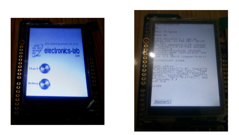
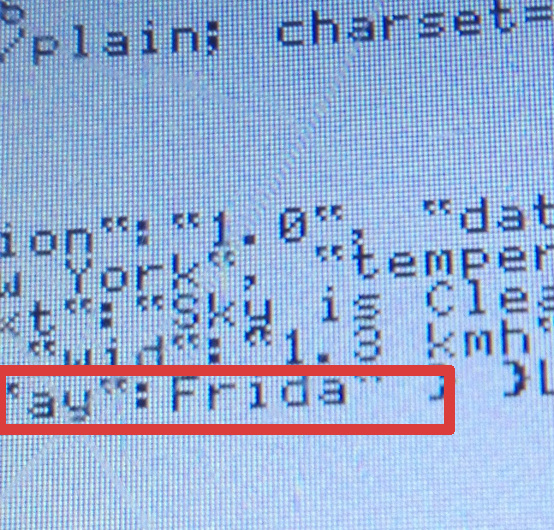
The concept of this demo is simple. 4Duino connects to my access point using the embedded ESP8266 module, then it makes a TCP connection with weathers.co website.
I used this website because it has a very simple and straightforward API.
The API allows you to retrieve information from the website via GET request, ex:
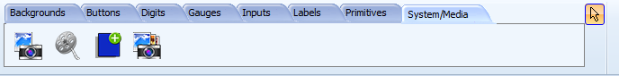
I used Extended Graphics environment because I needed to add buttons and the Logo of electronics-lab.
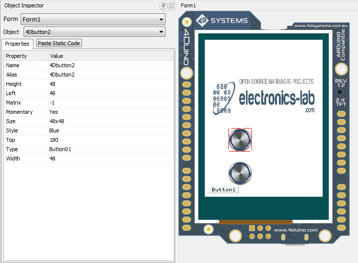
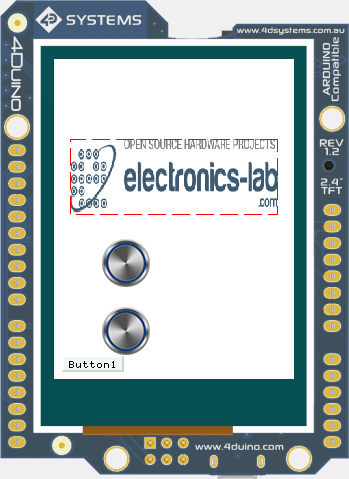
To insert images or buttons, you need to drag and drop these objects from widgets menu to the preview screen and the corresponding code will be generated.
As mentioned earlier, 4Duino has a feature-rich 4D Systems Picaso Graphics Processor connected with an SD card socket. 4Duino sketch uses Picaso Serial SPE Commands which are available to the user, to produce the Graphical User Interface required. I will list some of the commands that I used in the demo project.
Graphics Orientation gfx_ScreenMode(PORTRAIT)
graphics background colour gfx_BGcolour(WHITE)
text background colour txt_BGcolour(WHITE)
text foreground colour txt_FGcolour(BLUE)
Clear the screen gfx_Cls()
Move writing pointer gfx_MoveTo(5, 200)
Printing a string putstr()
Printing function pritnln()
Enable touchtouch_Set(TOUCH_ENABLE)
Return the touch state touch_Get(TOUCH_STATUS)
Return the touch position touch_Get(TOUCH_GETX)
Set the font txt_FontID(FONT1)
Set text wrap txt_Wrap(200)
To see the full list of the SPE functions, refer to this file (C:\Program Files\4D Labs\4D Workshop 4 IDE\Serial\PICASO\PROGRAM.INC) using Notepad.
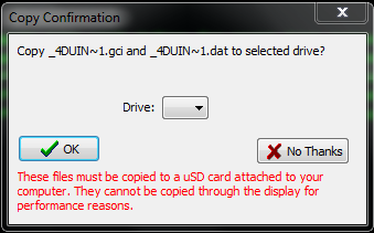
Before uploading the sketch file to 4Duino you need to upload the image files to the SD card using an SD card adapter.
Using 4Duino makes prototyping an IoT/connected/ordinary Arduino based application very fast and easy. I can say that I haven’t faced any major difficulties while developing this demo project.
But I think there are some issues that 4D Systems should take care of:
Workshop IDE is not so user friendly, especially the text editor. It is not rich with shortcuts and some important tools like “Auto format” are missing. Anyway, if you don’t feel comfortable with Workshop then you can use Arduino IDE.
Using Arduino Software Serial is not very stable. This issue is addressed by a lot of Arduino users and I’ve faced this problem in previous projects. It is common to have some corrupted data when using Software Serial.
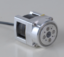
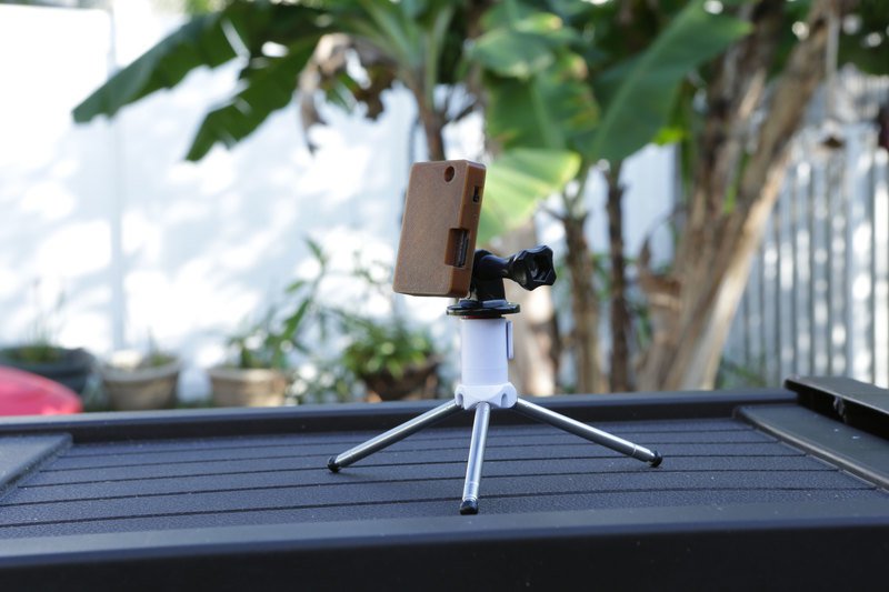
Using a mini spy camera module, Ruiz Brothers had built a tiny portable camera that is used to take time-lapse videos and for all sorts of photo based projects.
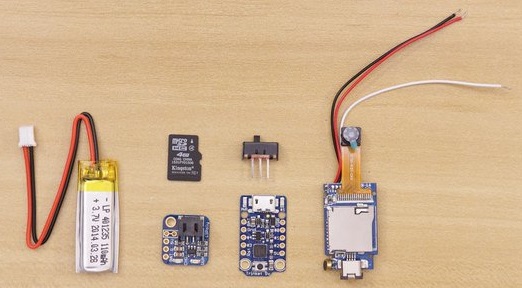
This project consists of these parts with an estimated cost of $39:
The mini spy camera module has an integrated driver and is easy to use without an Arduino or Raspberry Pi. The camera sensor can take 1280×960 photos and captures video at 480p. The module uses a microSD card to store data and it has a maximum support of 32GB. For a higher image quality and adjustable settings, you can use other camera modules such as the Wearable Raspberry Pi Zero Camera.
To take a time-lapse, an intervalometer remote control is needed to trigger the camera for capturing a photo within a constant interval. The Adafruit Trinket microcontroller is used here, and you can also make your own following this guide.
The circuit will be powered by a 3.7V 100mAh Lithium Ion battery via JST connection. The battery plugs directly into the Trinket Backpack, which allows the recharging over the microUSB port on the Trinket.
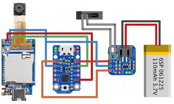
The circuit is connected as shown in the diagram; the slide switch to Lipoly backpack, VCC from camera to 5V on Trinket, GND from camera to GND on Trinket, BAT from Lipo backpack to BAT on Trinket, G from Lipo backpack to GND on Trinket, and 5V from Lipo backpack to USB.
The code is very simple and can be uploaded to the controller using the Arduino IDE. The setup loop will initialize the pins, and the loop will turn on and off the trigger with a chosen delay.
int trig = 0;
int led = 1;
voidsetup() {
// initialize the digital pins as output.
pinMode(led, OUTPUT);
pinMode(trig, OUTPUT);
digitalWrite(led, HIGH);
digitalWrite(trig, HIGH);
}
// Hold HIGH and trigger quick (<250ms) LOW to take a photo. Holding LOW and trigger HIGH starts/stops video recordingvoidloop() {
digitalWrite(trig, LOW);
digitalWrite(led, HIGH);
delay(50);
digitalWrite(trig, HIGH);
digitalWrite(led, LOW);
delay(5000);
}
The case in 3d printed, the design with a detailed description and the full making guide is available here. This video is showing how to make this tiny camera and how it works.


 Tinusaur comes as an assembly kit, in parts, all in a small plastic bag, so you have to solder it yourself. In order to program this microcontroller board you will need a programmer like
 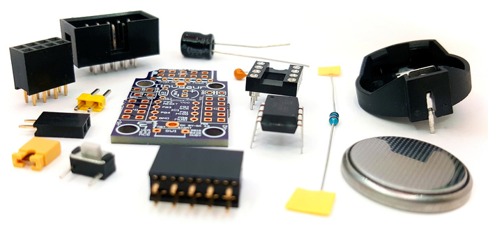 There is also the