Introducing Flowcode 7, The Electronic System Design IDE

Matrix Technology Solutions Ltd. is a premier, global provider of technology solutions. Since 1993, Matrix’s team of skilled Engineers have developed a wide range of Educational, Industrial and Hobbyist focused products simplifying subject matter including Electronics, Electricity, Programming, Robotics, Mechatronics, Technology and Computer Science.

One of the amazing products by Matrix Technology Solutions is Flowcode! Flowcode is an advanced integrated development environment (IDE) for electronic and electromechanical system development. Engineers – both professional and academic use Flowcode to develop systems for control and measurement based on microcontrollers or on rugged industrial interfaces using Windows compatible personal computers.

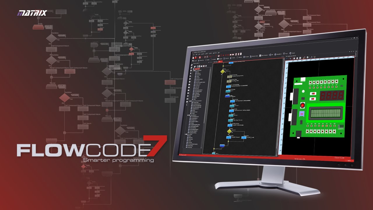
This video will give you a glimpse into what to expect from Flowcode:

Flowcode version 7 has some new developments which provide a fast and effective way to write complex projects for embedded systems. Flowcode is now launching a free version which will be a good tool for learning programming and developing applications at home or for prototyping designs. But it is not licenced for commercial or educational institution use.  In the other hand, Flowcode comes with a flexible licensing structure that can be customized by users’ requirements.

Features of Flowcode 7

    • Simple, flowchart icons: easy to use graphical icons to develop your system, including a feature of customizing your code sections with color for easier navigation.
    • Fast System development: Flowcode is well-designed to deliver the best development experience for you with minimum, or zero errors.
    • Ghost Technology: An advanced way of testing and debugging your electronic system. Using Matrix’s E-blocks hardware,you can monitor every pin on your microcontroller and monitor and interpret serial data inputs and outputs.
    • Simulation debugger: to know how much the design goes with your code and it is used to monitor the values and macros called in your system.
    • Create Simple Designs: Flowcode gives you the ability to create your own 3D designs and test them with other sides of your project.
    • Pre-developed components: A large set of components are provided to enlarge the scope of your project and it is designed to function perfectly with other components.
    • Devices support: like E-Blocks, MIAC, Arduino, 8bit-16bit-32bit PIC, Microchip templates and AVR & ARM.

These are not all the features coming with the latest version of Flowcode. You can check this page to learn more, and also check this video to see them in action:


“At Cambridge Regional College we teach students from the BTEC level 2 up to HND. Flowcode has become an essential part of the coursework and fits in extremely well with the syllabus. Flowcode offers our students an overview of microcontroller systems and allows problematic thinking to evolve with microelectronic designs.” said Steven Collins from Cambridge Regional College, a leading Centre of Vocational Excellence and one of the UK’s largest FE providers of programmes for overseas students . He added: “We believe the Flowcode experience is something students should all have access to for its designing and learning possibilities. The people at Matrix have created something truly amazing and Flowcode cannot be called anything other than a world class product.”

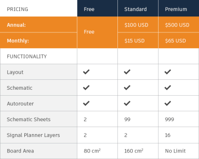
Talking about Premium plans, Flowcode has three licenses: Standard User License, Professional User License, and Academic User License. Getting Flowcode 7 AVR/Arduino Chip Pack costs around $100 as per the standard license, where prices rise around $200 while purchasing the professional license. Flowcode now is available for pre-ordering, you can check full details and pre-order Flowcode 7 at the buying guide page and the purchasing page. More information can be found at this detailed datasheet.

DIY power supply with 3D printed enclosure

Rui Cabral tipped us with his latest video. It’s about a dual output power supply build in a 3D printed enclosure. Main parts used are a 100W AC-DC converter (110V 220V to 24VDC 6A) and LM2596 DC-DC Buck converter constant current voltage adjustable module. The power supply has two voltage outputs, a fixed 5V output and a variable output (1-24V). The enclosure 3D files are available here.

DIY power supply with 3D printed enclosure – [Link]

Expand Your ESP8266 Analog Inputs With $10

ESP8266 is a very powerful module for building an IoT or WiFi-based project. But since it has only one analog input, you may need to use another microcontroller or circuit to connect multiple sensors and data sources with your ESP8266.

Allaboutee created the second version of their analog expander board. Simply it is a board that lets you add eight analog inputs to your ESP8266 via I2C, the first version had only four inputs.

The expander is a 19x14mm board that is powered by a range of 2.7V to 3.6V, features 8 10-bit resolution analog inputs for sensors with an output voltage lower than 3.3V. Allaboutee developed some open source, easy to use libraries and examples:

Expander pinout:

  • VDD – 2.7V to 3.6V (If using with ESP8266 you’ll have to use 3.3V for this pin).
  • GND – Ground
  • SCL – I2C clock (connect this to GPIO0 of the ESP8266)
  • SDA – I2C data (connect this to GPIO2 of the ESP8266)
  • A0 -> A7 – Analog inputs (0v to 3.3V)

You can not use two or more boards to have more than 8 analog inputs because the chip’s I2C is factory fixed. If you do not connect a pin to anything, it will be “floating”, that means it’s value is not defined so it can be anything.

This video shows the expander board in action:

ESP8266 expander is available for $10 at tindie, it may be a bit expensive but with the cost of ESP8266, it is a very cheap alternative of the $100 Arduino Wifi shield.

“If you were to desire an Arduino based and thus easy to program, WiFi enabled microcontroller, then you could purchase an Arduino WiFi shield for $100+, OR you could instead get an esp8266 w/ breakout board for $6, A 3.3v voltage regulator for $1, the analog input expander $10 and an FTDI to USB 3.3v programmer $3.” – A review by Erol

USB Volume Control and Caps Lock LED

p_leriche @ instructables.com build a USB volume control which is simple, cheap and extensible. Check it out:

I’m not the first person to publish an Instructable for a USB volume control, but I think this one is about as simple and cheap as it gets, and at the same time can be extended at minimal cost to various other functions such as:

  • Mute, Play, Pause and various other media buttons
  • Keyboard LEDs such as Caps Lock, Scroll Lock and Num Lock (a kana LED is also defined for Japanese users)
  • Application launch buttons such as browser, email, calculator etc
  • Browser navigation and other application control buttons
  • Gamepad buttons
  • System buttons for functions such as Sleep, Hibernate, Wake, Power down
  • Mouse buttons and movement

and many more, subject to support being provided by your operating system. Mine implements the volume and mute functions (mute by pressing the knob) and the 3 main keyboard LEDs.

USB Volume Control and Caps Lock LED – [Link]

LED Based Strobe For Entertainment, Events & Warning Signals

Strobe provides regular flashes of light. Usually Strobes are designed using Xenon Tubes. Here is LED based simple solution that can be used as strobe for entertainment and events and also as warning signals. Project is based on PIC16F1825 micro-controller with two digit frequency display.

Project provides TTL output signal, frequency 1Hz-25Hz, Tact switches provided to set the frequency.

This project works along with DC Output Solid State Relay

Features

  • Supply 4.5 to 5V DC
  • Frequency 1Hz To 25Hz
  • Easy Interface with Relay Board
  • Easy Interface with Solid State Relay
  • On Board Power LED
  • On Board Output LED
  • Onboard Switch to set the frequency
  • 2X7 Segment 0.5 Inch Display

LED Based Strobe For Entertainment, Events & Warning Signals – [Link]

LED Based Strobe For Entertainment, Events & Warning Signals

Strobe provides regular flashes of light. Usually Strobes are designed using Xenon Tubes. Here is LED based simple solution that can be used as strobe for entertainment and events and also as warning signals. Project is based on PIC16F1825 micro-controller with two digit frequency display.

Project provides TTL output signal, frequency 1Hz-25Hz, Tact switches provided to set the frequency.

This project works along with DC Output Solid State Relay

Features

  • Supply 4.5 to 5V DC
  • Frequency 1Hz To 25Hz
  • Easy Interface with Relay Board
  • Easy Interface with Solid State Relay
  • On Board Power LED
  • On Board Output LED
  • Onboard Switch to set the frequency
  • 2X7 Segment 0.5 Inch Display

Applications

  • Strobe for Entertainment
  • Traffic Signal
  • Warning Signal
  • Ambulance Warning Signals

Schematic

Parts List

Connections

Photos

Working Diagram

Video

DIY BLE Thermometer With Arduino and Blynk

Konstantin Dimitrov has shared a new tutorial on Arduino Project Hub on how to make an Arduino/Genuino 101 Bluetooth Low Energy (BLE) thermometer with TMP102 and Blynk. Blynk is a platform with iOS and Android apps to control Arduino, Raspberry Pi and the likes over the Internet. You can easily build graphical interfaces for all your projects by simply dragging and dropping widgets.

You will need:

In order to program this project, you should first include Blynk library by going to:

Sketch => Include Library => Manage Libraries. Click on “Manage Libraries”, then type Blynk in the search bar and you will get the library.  You should scan this QR code once you install the Blynk app on your smartphone to complete the settings.

“Now you need to get the “Auth Token”. Tap on the “Nut” icon then tap on the device and again on it, now you should see your “Auth Token”. E-mail or rewrite it, cause you will need it in the next step !”

In order to connect the Blynk app, tap on the Bluetooth app, tap on “Connect BLE Device” and choose your 101 board. You are now connected!

Finally upload this sketch on you Arduino:

/**************************************************************
 * Blynk is a platform with iOS and Android apps to control
 * Arduino, Raspberry Pi and the likes over the Internet.
 * You can easily build graphic interfaces for all your
 * projects by simply dragging and dropping widgets.
 *
 * This sketch was created by Konstatin Dimitrov 
 * under GNU v3.0 Licence 
 * 
 * Based on example scetch: Arduino_101_BLE
 ***************************************************
 *
 * This scetch shows how to send data from TMP102 with 
 * Arduino/Genuino 101 BLE to Blynk.
 *
 * Note: This requires CurieBLE library
 *   from http://librarymanager/all#CurieBLE
 *
 * NOTE: BLE support is in beta!
 *
 **************************************************************/

//#define BLYNK_USE_DIRECT_CONNECT

#define BLYNK_PRINT Serial

#include <Wire.h>
#include <BlynkSimpleCurieBLE.h>
#include <CurieBLE.h>

// You should get Auth Token in the Blynk App.
// Go to the Project Settings (nut icon).
char auth[] = "AUTH_TOKEN";

//TMP102 I2C (TWI) address in HEX
int tmp102Address = 0x48;

BLEPeripheral  blePeripheral;

void setup() {
  Serial.begin(9600);
  Wire.begin();
  delay(1000);
  
  blePeripheral.setLocalName("BLE Thermometer");
  blePeripheral.setDeviceName("BLE Thermometer");
  blePeripheral.setAppearance(384);

  Blynk.begin(blePeripheral, auth);

  blePeripheral.begin();
  
  Serial.println("Waiting for connections...");
}

//Temperature readings in Celsius on V0
BLYNK_READ(0)
  {
  float celsius = getTemperature();
  Blynk.virtualWrite(0, celsius);
  }
//Temperature readings in Fahrenheit on V1
BLYNK_READ(1)
  {
  float celsius = getTemperature();
  float fahrenheit = (1.8 * celsius) + 32;
  Blynk.virtualWrite(1, fahrenheit);
  }

BLYNK_READ(2)
  {
  float celsius = getTemperature();
  float kelvin = 273.15 + celsius;
  Blynk.virtualWrite(2, kelvin);
  }
  
void loop() {
  Blynk.run();
  blePeripheral.poll();
  }

float getTemperature(){
  Wire.requestFrom(tmp102Address,2); 

  byte MSB = Wire.read();
  byte LSB = Wire.read();

  //it's a 12bit int, using two's compliment for negative
  int TemperatureSum = ((MSB << 8) | LSB) >> 4; 

  float celsius = TemperatureSum*0.0625;
  return celsius;
}

To know more details, check the project’s page. Also check more projects by Konstnatin and follow him!

Make an Arduino Temperature Sensor (Thermistor Tutorial)

In this video, Circuit Basics walks us through the steps in setting up a thermistor temperature sensor on an Arduino Uno. First they show how to output the temperature readings to your serial monitor. Then they go over how to connect and output the temperature readings to a 16×2 LCD display.

Make an Arduino Temperature Sensor (Thermistor Tutorial) [Link]

EAGLE Is Now Released By Autodesk

After acquiring CadSoft in June 2016, Autodesk released a new version of EAGLE with new features that improve program functions and a new pricing plan.

The new version of Eagle added a modular design blocks feature to the schematic editor that allows you to quickly replicate sections of circuitry between multiple projects. Even better, any change you make stays synchronized between your schematics and PCB.

The route engine comes with new, interactive routing features that make it easy to design beautifully precise PCB layouts. It includes a whole set of trace clean-up tools that makes it much easier to tidy up your board and make adjustments to existing paths. There is also an automated loop removal, cornering for super-smooth tracks, quick and easy via placement while routing.

Autodesk said that upgrading EAGLE will be available as a monthly or yearly subscription, providing continuous updates and better support, and it said to be budget friendly. Which means that users will get more consistent and frequent updates backed with dedicated support from the PCB design pros at Autodesk, and cheaper than buying a cup of coffee every day for a year.

Eagle Pricing Table

Many Eagle users found it a bad deal, because having the old Standard option will cost $100/year instead of the one-time $69 payment. Autodesk also killed the lower cost options for non-commercial use, what used to be a $169 version that was positioned for hobbyists.

“We know it’s not easy paying a lump sum for software updates every few years. It can be hard on your budget, and you never know when you need to have funds ready for the next upgrade.”

You can download the free version from here, but for anyone using Eagle for commercial purposes this is a big change. Even if you agree with the new pricing, a subscription model means you never actually own the software. This model will require licensing software that needs to phone home periodically and can be killed remotely. If you need to look back at a design a few years from now, you better hope that your subscription is valid, that Autodesk is still running the license server, and that you have an active internet connection.

KiCad appears as the alternative software for Eagle users, and many of the PCB designers planned to start using it as it has been improving steadily in the past years.

0.91 inch OLED display targets wearables

Winstar’s WEO012832F is a small OLED display featuring 128×32 pixels in a 0.91 inch diagonal screen, suitable for wearable devices. by Julien Happich @ edn-europe.com:

The WEO012832F module comes with a built-in SSD1306BZ controller IC, it supports an I 2C interface and a 14-pin FPC pinout.  Standard emitting colours for the WEO012832F are available in white, sky blue and yellow. The WEO012832F features a COG structure OLED display, the built-in voltage generation only requires a single 3V power supply. This lightweight 30.0×11.5×1.45mm OLED module can operate at temperatures from -40℃ to +80℃.

0.91 inch OLED display targets wearables – [Link]

TOP PCB Companies