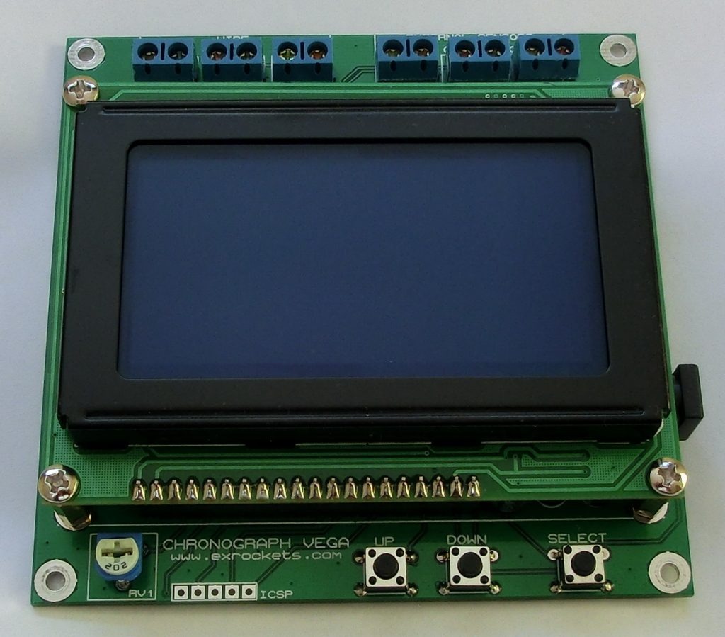
“pinko” build a high resolution chronograph which has some great features. Check it out:
This is a project is for chronograph that was purposely build for a good friend of mine to be used for accurate measuring of high speed processes.
I am using two timers and the chronograph has three inputs, as depicted on the principal flow chart, which mean that Input1 trigger the start for timer1 and Input2 triggers the stop for timer1. In the same time Input2 will start timer2 and finally Input3 will stop timer2.
Based on the preselected distance and the detected time by the timer, the MCU will calculate and visualize the speed of the process and if you used three sensors then you can calculate the acceleration based on both speeds.
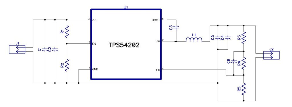
The circuit shown here is a step down converter which can convert an input voltage varying from 8V to 28V to 5V. The circuit is based on TPS54202, which is a 2A synchronous buck converter. This IC has several features such as over-voltage protection and peak current mode control.
Features
Input(V): 8V DC to 28V DC
Output(V): 5V DC
Output load: 2A
PCB:25mmX15mm
5V @ 2A Step Down Converter using TPS54202 – [Link]
Why would anyone even try to build a power bank – i.e. an external battery for charging mobile devices – these days? These things are commodity, it’s impossible to compete. Right? Well, that is until you find out that the type of power bank for your application, namely charging a higher-end tablet with 12V input, does not exist cheaply. Looking around for 12V power banks yields a lot of li-ion car jumpstarters (*) and very few actual power banks. Those that exist are pretty expensive and often don’t even perform that well.
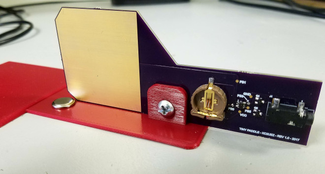
Edgarimplemented capacitive touch sensing using an ATTiny4 to create a touch paddle for Morse code:
Like many no-code operators, after being on the air for a while, I developed an interest and appreciation for Morse Code [..] I purchased a cheap paddle, but I found the clicking noise a little bit annoying.
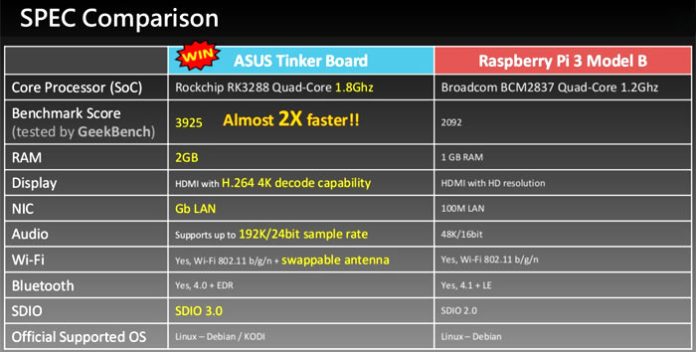
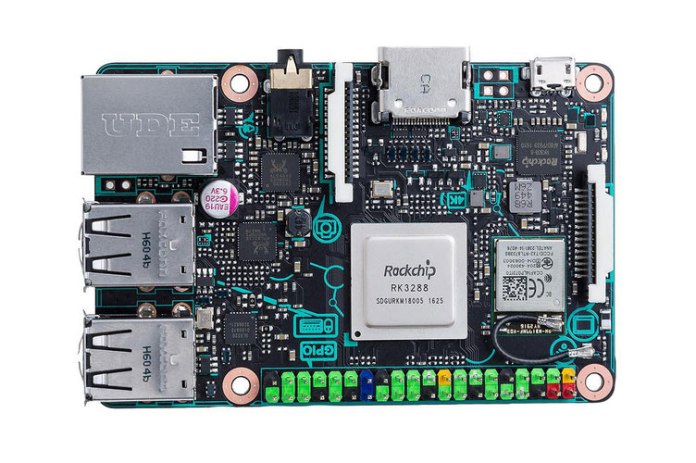
Raspberry Pi has been the household name for many years now, and many other companies have tried to replace it with their offering, but no one sussed to replace Raspberry Pi by performance and low-cost. Though, that might change as ASUS are entering the arena with their 90MB0QY1-M0EAY0 Tinker Board, which have better components across the board.
According to Hexus.net, ASUS believes the capabilities of the Tinker Board will make possible projects that were too much to ask of even for the newest Raspberry Pi revision. Discussing the reasoning behind the creation of the ‘ASUS Pi’, the Taiwanese computer firm said:
“Raspberry Pi has been in the market for so long, we’re here to expand users’ choices with more options. And this board has 4K support, higher SoC performance, faster Ethernet transmission, and flexibility for the memory size.”
The ASUS Tinker Board (90MB0QY1-M0EAY0) features Rockchip RK3288 quad-core SOC running at 1.8GHz with 2GB of RAM, which gives almost two times faster that Raspberry Pi 3’s Broadcom chip. The Tinker Board also comes with H.264 4K decode abilities and SDIO 3.0. Below you can see the specification diffraction between ASUS Tinker Board and Raspberry Pi 3.
The Raspberry Pi 3 is available at a price of around £34, with the ASUS Tinker board coming with a slightly higher price around £45-55 depending on the retailer.
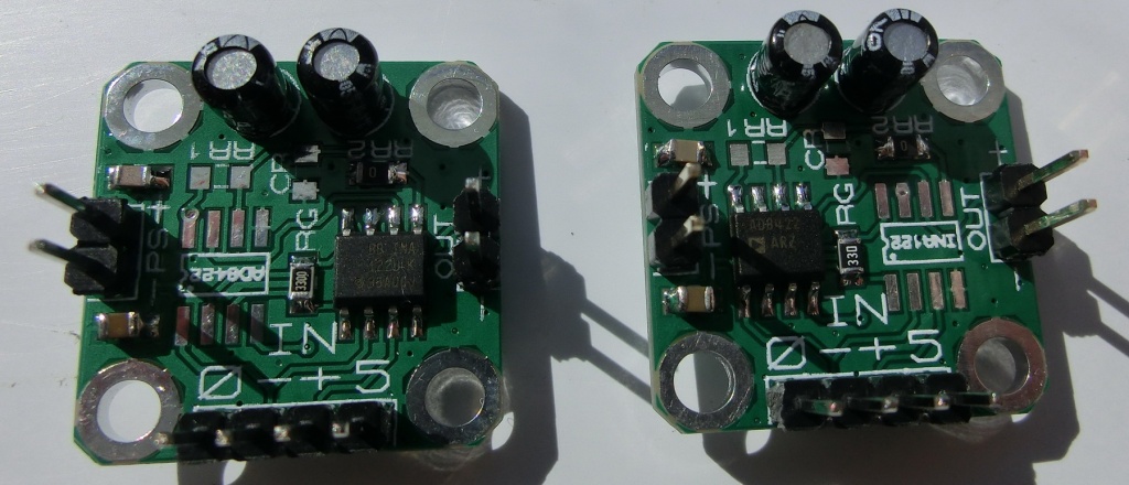
pinko @ blog.exrockets.com wanted to test some cheap load cells so he decided to build his own load cell amplifier. He writes:
Both IA are Rail-to-Rail, single or dual power supply instrumentation amplifiers, however with different standard pin-outs. The gain is set by RG. RR1 and RR2 and CR form a voltage divider that could be used to offset the output signal. If no output level shift is desired then RR1 and CR should be omitted and RR2 should be a 0R resistor.
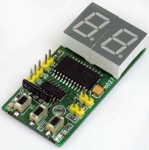
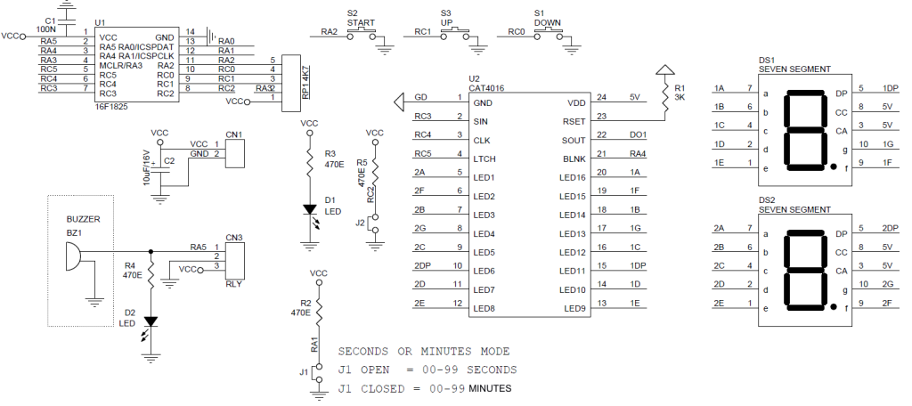
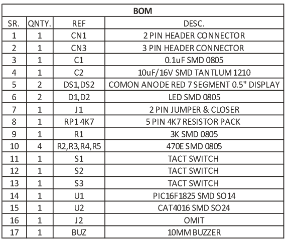
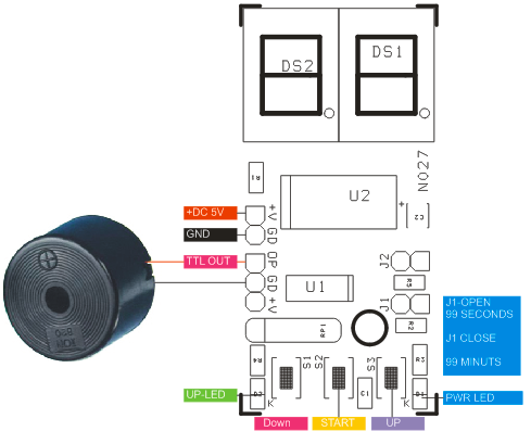
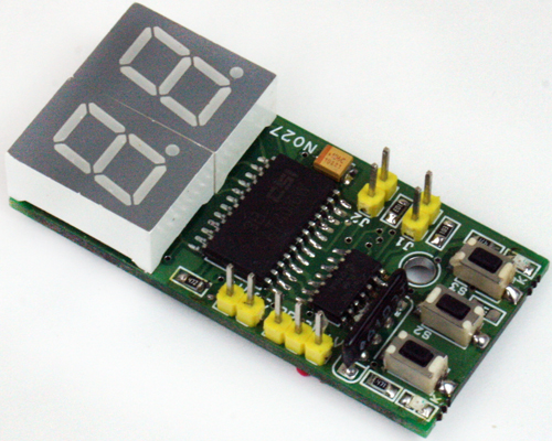
The projects shown here is a 2 Digit 00-99 Seconds or 00-99 Minutes Countdown kitchen timer based on PIC16F1825 micro-controller. The timer is useful in various applications like Cooking, Sports, Industrial, Sleeping. On board switches provided to set the time and start, a jumper to select the mode 99 Seconds or 99 Minutes. TTL output directly drives the Buzzer.
Features
Supply 5V DC
Timer 0-99 Seconds Or 0-99 Minutes
On Board Power LED
On Board Output LED
Jumper J1 Mode Selection Open Seconds, Closed Minutes
It’s possible – there are a lot of fakes out there. Maybe you bought a counterfeit Arduino. Was it priced lower that normal? Is it missing the small details that make it a genuine Arduino board? Watch the video to find out if your Arduino is real or fake.
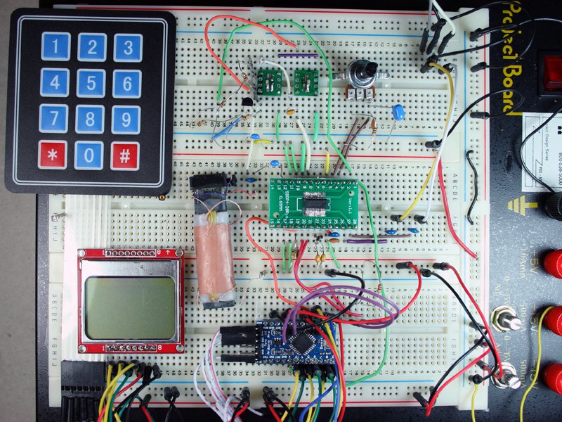
Combine the Si4844-A10 analog-tuned radio receiver with an Arduino to make a full-featured multiband radio.
The idea of a single chip radio is intriguing. The prospect is especially interesting to me because, frankly, I envy the analog skills I associate with building a radio receiver. When I browsed the circuit literature in the area, I came across the Silicon Labs collection. One of their chips, the Si4844-A10 caught my attention. This receiver has AM/FM/SW capability with all the bells and whistles and it is designed to work with a microprocessor. Best of all, the support components required are mainly associated with the microprocessor display and control functions with only a small amount of antenna support needed. I couldn’t resist taking the plunge.


 According to