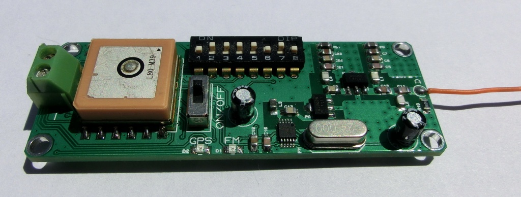
pinko @ blog.exrockets.com has build a GPS receiver to FM radio based on PIC18LF2553. He writes:
Today I made some modifications to this is a new project for a GPS to FM radio tracking device for rockets i.e. the V2. The initial design lacked the antenna impedance matching circuit which caused problems with the end amplifier. Also I increased the possible choices of frequencies, see the table further down. Now instead of soldering and de-soldering tiny resistors, the frequency and the transmitting modes are selected via a DIP switch.
GPS RECEIVER TO FM RADIO (88-107 MHz) AUDIO + RDS TRACKING V2 – [Link]
One of the most harmful airborne pollutants with respect to human health is particulate matter. Air particle counters are used to determine the air quality by counting and sizing the number of particles in the air. This information is useful in determining the amount of particles inside a building or in the ambient air. It is also useful in understanding the cleanliness level in a controlled environment.
Airborne particles with a diameter of less than 10 microns pose a large risk, they can travel deeply into the respiratory system, causing a variety of cardiovascular and respiratory diseases. Combustion (e.g. burning wood; automobiles) can generate particles less than 2.5 microns in diameter. Between 2.5 and 10 microns are particles such as dust, pollen, and mold. (More information about particulate matter can be found here.)
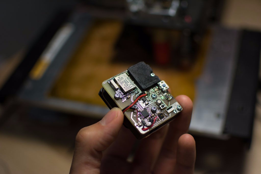
Four members of the Hybrid Ecologies Lab at UC Berkeley, Rundong Tian, Sarah Sterman, Chris Myers, and Eric Paulos, developed “MyPart”, a device that attempts to measure air particulate matter.
MyPart’s design focuses on four goals; accuracy, size and portability, cost, and open source.
Accuracy
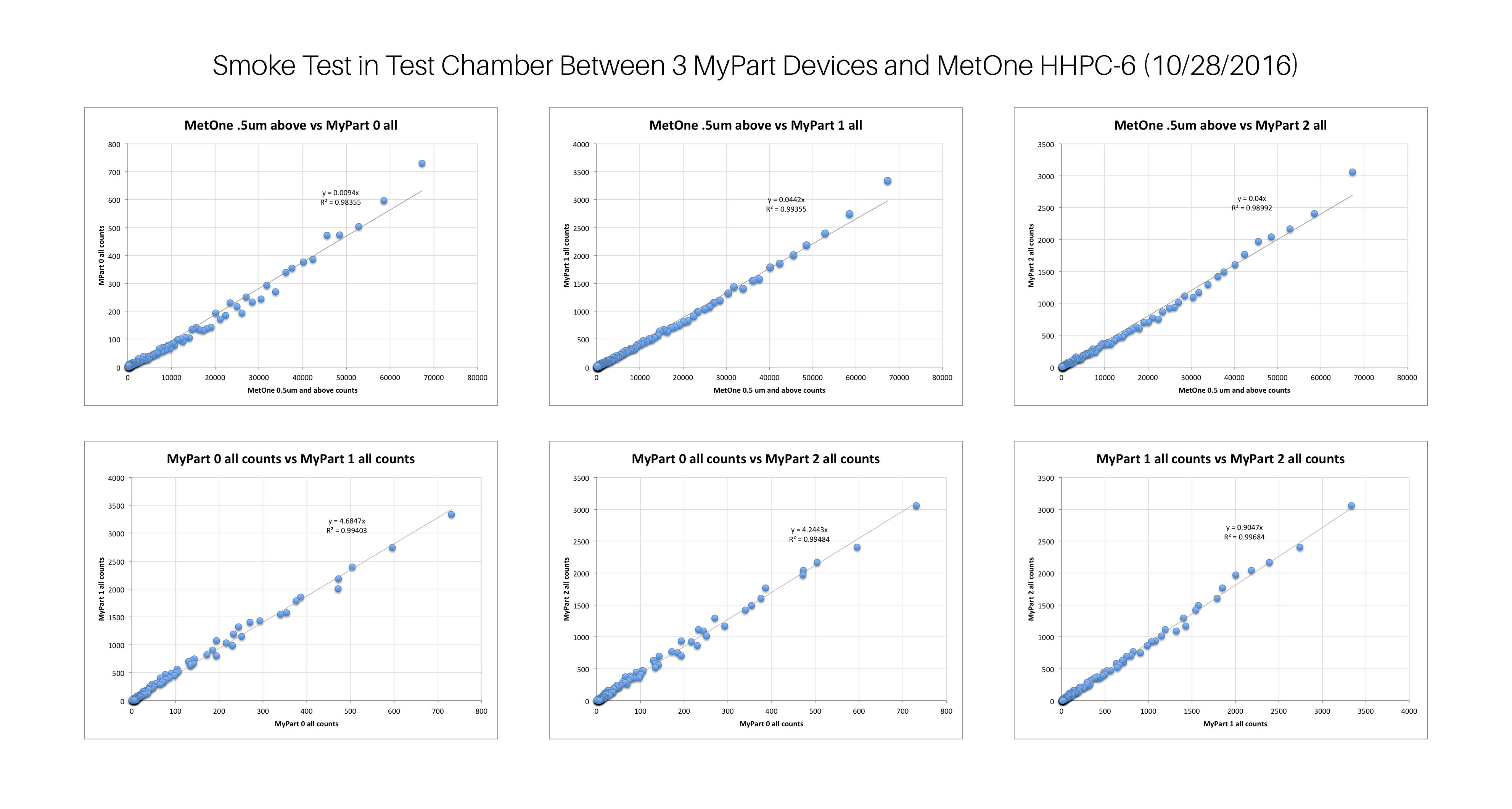
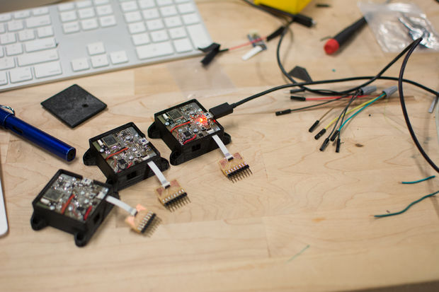
In the test chamber, smoke concentration was allowed to decay naturally over about 2 hours. Three prototypes of MyPart gave similar accuracy results to an expensive instrument results ($5000 MetOne HHPC-6).
Additional experiments conducted with calibration particles of known sizes and in outdoor ambient environments, and more information about the tests can be found here.
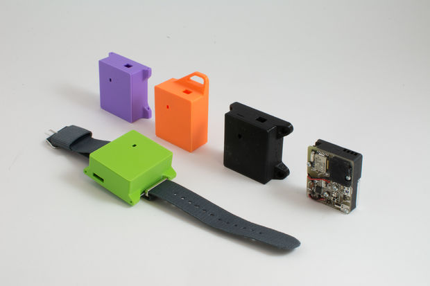
Size & Portability
The overall size of the inner sensing chamber is 18mmx38mmx45mm. These dimensions include an onboard 400mAh battery. The components related to the sensing are completely separated from the outer casing, which allows various form factors to easily be explored, developed, and shared.
MyPart sensor consumes about 2 mA while sleeping, and about 70mA during sampling.
Cost
The total cost for the bill of materials is around $75 without the cost of the digital fabrication tools required to make the components (3D printer and CNC mill). This BOM prices are for electrical components in quantities of 1 or 2, which will drop dramatically when purchased in bulk.
Open Source
MyPart’s original design files and source codes are all open source in order to give people the base form which to make and modify their own sensors, to set up sensing in their own communities, and to generate reliable air quality data.
The full BOM can be found here. The fabrication files, as well as the original design files can be found here.
MyPart’s Parts
Top air channel, Contains the main flow channel, a light trap for the laser light, and the air inlet.
Bottom air channel, Contains features to hold the fan, and the air outlet
Analog cap, shields the sensitive analog circuitry from ambient light
Fan, pulls air through the channel
Laser, focused light source to illuminate particles in the airstream
Laser holder, aligns the laser to the photodiode
Limitations
Optical scattering: The quantity and direction of light scattered by a particle is dependent on the size, composition, and shape of the particle, as well as where it strikes the laser beam. Because of these factors, accurate sizing of particles tends to be difficult with optical scattering sensors. However, rough size cutoff bins can still be produced by using the amplitude of signal peaks.
Full documentation, technical details, and how to build guide are reachable at this seeedstudio article and this instructable.
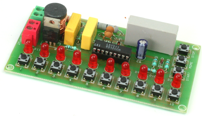
The project specifically designed for motor speed control application in appliances such as blenders, etc. Tact switches provided for selecting/indicating from 1 to 10 power levels ( Speed Levels). The project is ideal for universal and shaded-pole motor speed control for modern appliances design. Eliminates awkward mechanical switch assemblies and multi-taped motor winding.
Features
10 Tact Switch for Speed Selection
10 LEDS for speed indication
On Board Stop and Start Switches ( Start Switch Latch Operation)
Momentary Run Switch
Supply 230V ( 110V Possible Refer Data sheet for components Change)
300W Load
On Board snubber for Inductive Load
No Separate DC power supply required
AC Motor Speed Controller for Modern Appliances Using LS7311 – [Link]
A lot of project are battery powered and some of them need dual battery links. Robert on hackaday.io had shared his new project that shed light on this issue. He built an load sharing addon board with the ability to charge the battery while the project is operating.
Many Chinese charger boards are out there based on TP4056, but these boards don’t have the load sharing or voltage regulator features.
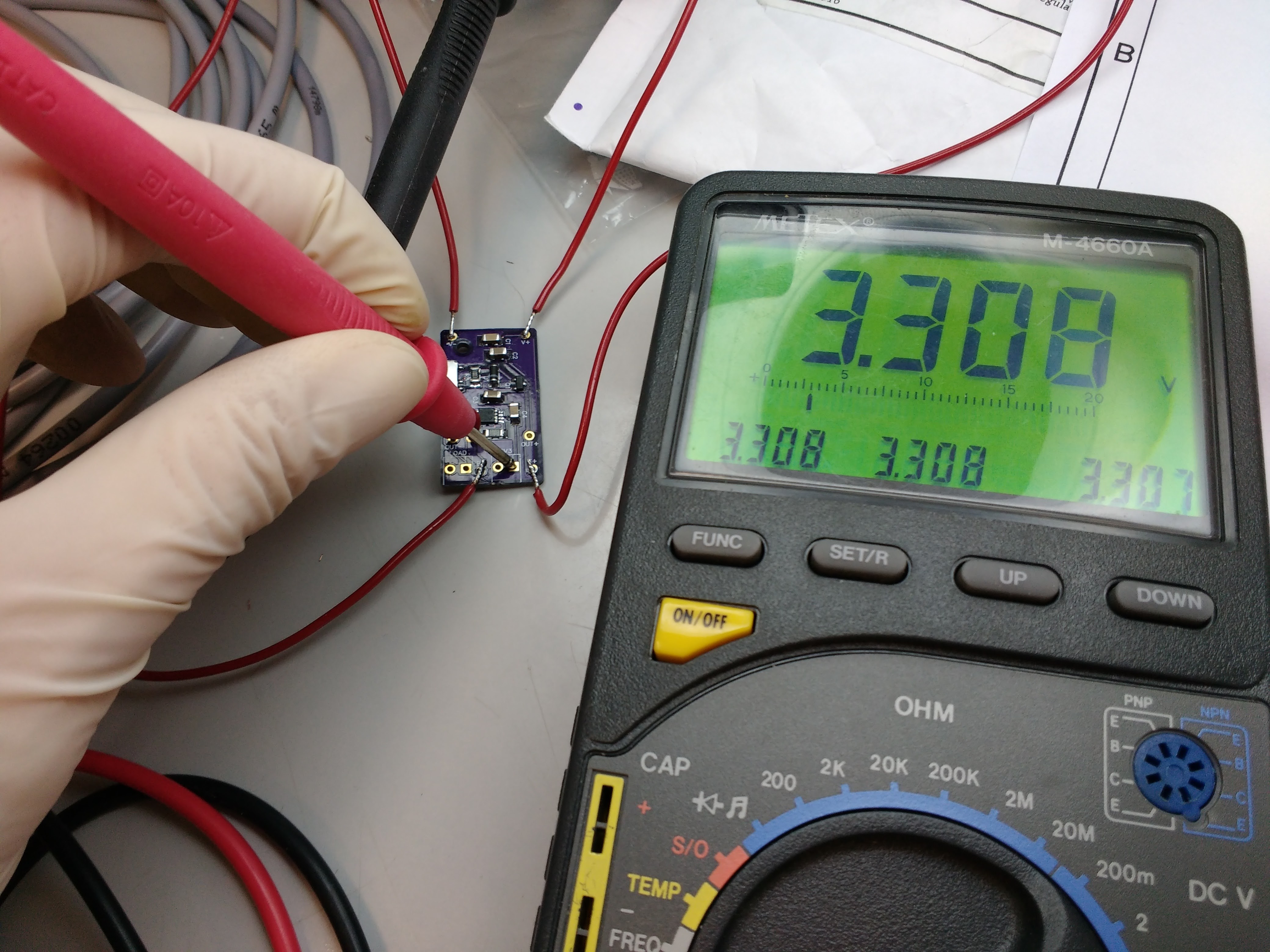
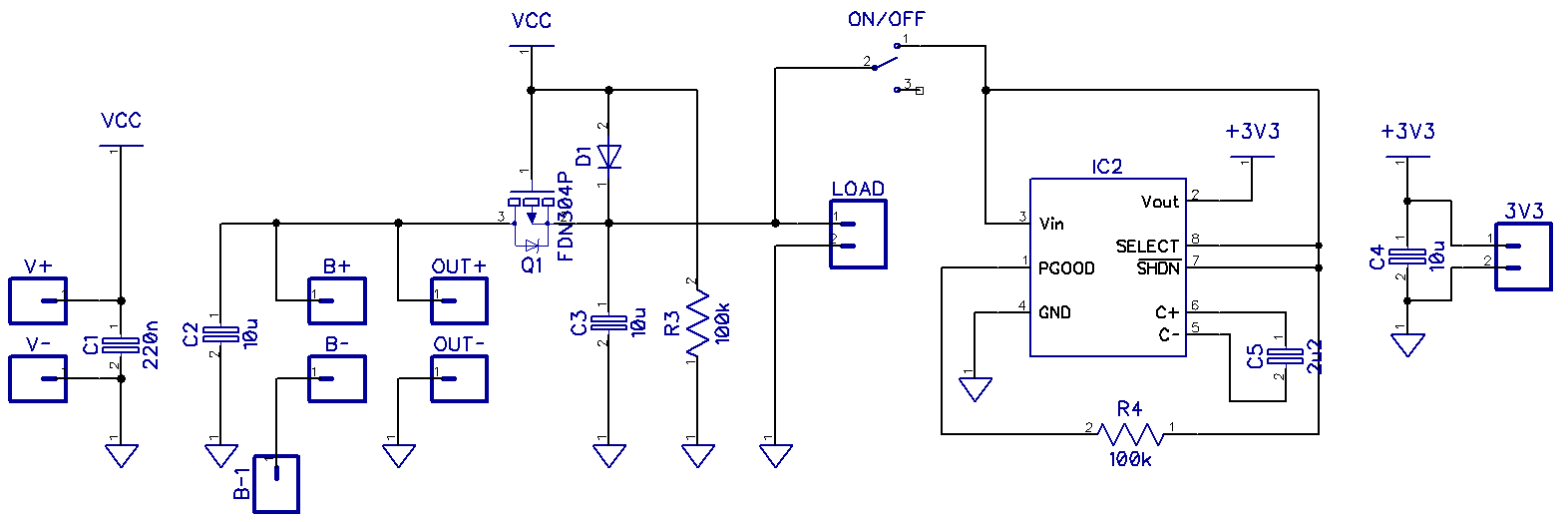
Load sharing means that you can power your circuit in two ways, from battery and from Vcc if a charger is connected. Once the charger is connected the battery will start charging and the load will be powered directly from Vcc. Robert added this feature to a recent design and also he added voltage regulation by using MCP1252.
This schematic was inspired by multiple designs and modified by Robert.
“The advantage of MCP1252 is automatic buck/boost feature, it will maintain the regulated output voltage whether the input voltage is above or below the output voltage (2.1 to 5.0 V input range) so it is ideal for the lithium battery voltage. If you read the datasheet for the MCP1252-33X50I/MS there is clearly specified what type of MLCC capacitor should be used.”
The maximum output current of this board is 120mA and the output voltage is 3.3 V. It may sound not that suitable for your projects if you want to power an ESP8266, but still you can build your own board with different components to achieve the outputs you need. For example, by using MCP1253, which is identical to MCP1252, you will get higher switching frequency (1MHz). Robert’s plan is to use this board with CO2 sensor (about 30 mA) and other low power sensors, some MCU and LCD, which can be powered using 120 mA.
Some measurements will be done to test the functionality of this board. To keep updated with the news of this project, you can follow the project on hackaday.io. You can also check other projects by Robert here.
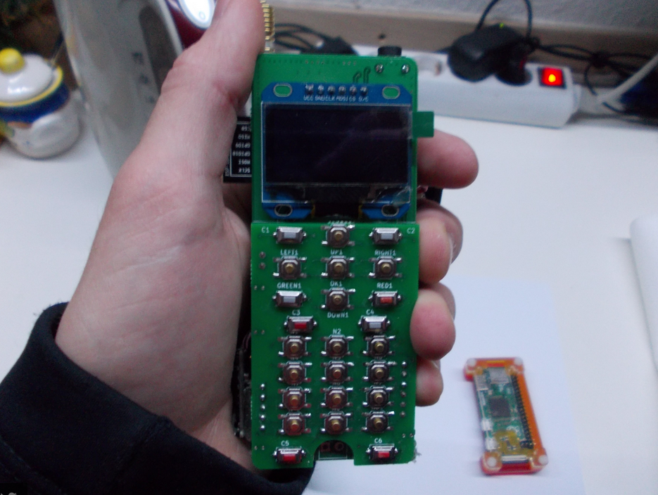
Arsenijs build a Pi-powered open-source mobile phone (that you can assemble for 50$ in parts).
Currently, it costs about 50$ in parts, and all the parts are available on eBay. No BGA or other difficultly solderable ICs are used (with the obvious exception of Pi Zero). User interface is written using Python, and there’s a phone-tailored UI framework in the works (so far, it uses pyLCI for interfacing). However, even current state of it is further that other projects have come.
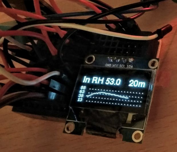
Starting playing with Arduino seems simple enough. You can find all sorts of tutorials, instructables, wiring and code examples for pretty much every sensor, component, or module available. So far so good. But when the time comes for building a more complex device, the troubles start. The tutorials for adding multiple modules to Arduino and then working with them efficiently are very scarce. Therefore, with this instructable, I will try to help with just that. So here comes the Arduino thermometer/hygrometer with a GUI, designed to push Arduino to its limits.
Thermometer That Pushes Arduino to Its Limits – [Link]
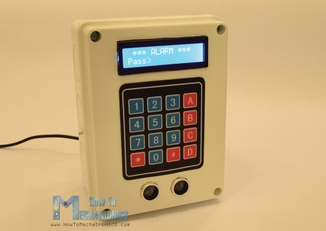
Dejan Nedelkovski had built an Arduino security and alarm system project that uses an ultrasonic sensor for detecting objects and a buzzer for notification.
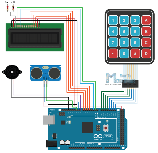
Components needed to build this simple system are: Arduino board, LCD display, 4×4 keypad, ultrasonic sensor and buzzer. The circuit can be connected as shown in the schematics below.
In order to build the project, you have to connect the buzzer with a PWM pin and the keypad pins where 4 of the 8 pins are for rows and the rest are for columns.
“The 4×4 keypad has 8 pins, 4 of them are for the rows and 4 of them for the columns of the keypad. Each button is actually a push button switch which makes a short between one row and column when pressed. So, for example, if we set the row 1 line low, and all column lines high, when we will press, for example, the button 3, due to the short between the two lines, the column 3 line will drop to low so in such a case we can register that the button 3 has been pressed.”
For connecting the LCD display and ultrasonic sensor you can check this detailed video tutorial by Dejan Nedelkovski and to see the project in action:
We want to activate the alarm by setting the A button to activate it. B button is used to change the password, and you need to enter the preset password “1234” to be able to change it.
After activating the alarm by pressing A, a 200 milliseconds sound will be produced from the buzzer showing that the alarm is now active. A message on the LCD display will appear to saying “Alarm will be activated in” and a countdown will be running afterwards until the alarm is completely active. At the end of the countdown a ” Alarm Activated” is on the display and the sensor will start working. Comparing with the initial distance at the start, the sensor will measure the distance is smaller than the initial distance, corrected by a value of 10 cms. The buzzer will produce a sound if an object is observed as per the condition.
Here’s the complete source code of the Arduino alarm system:
/** Arduino Security and Alarm System** by Dejan Nedelkovski,* www.HowToMechatronics.com**/#include <LiquidCrystal.h> // includes the LiquidCrystal Library #include <Keypad.h>#define buzzer 8#define trigPin 9#define echoPin 10long duration;
int distance, initialDistance, currentDistance, i;
int screenOffMsg =0;
String password="1234";
String tempPassword;
boolean activated =false; // State of the alarm
boolean isActivated;
boolean activateAlarm =false;
boolean alarmActivated =false;
boolean enteredPassword; // State of the entered password to stop the alarm
boolean passChangeMode =false;
boolean passChanged =false;
const byte ROWS =4; //four rowsconst byte COLS =4; //four columnschar keypressed;
//define the cymbols on the buttons of the keypadschar keyMap[ROWS][COLS] = {
{'1','2','3','A'},
{'4','5','6','B'},
{'7','8','9','C'},
{'*','0','#','D'}
};
byte rowPins[ROWS] = {14, 15, 16, 17}; //Row pinouts of the keypad
byte colPins[COLS] = {18, 19, 20, 21}; //Column pinouts of the keypad
Keypad myKeypad = Keypad( makeKeymap(keyMap), rowPins, colPins, ROWS, COLS);
LiquidCrystal lcd(1, 2, 4, 5, 6, 7); // Creates an LC object. Parameters: (rs, enable, d4, d5, d6, d7) voidsetup() {
lcd.begin(16,2);
pinMode(buzzer, OUTPUT); // Set buzzer as an output
pinMode(trigPin, OUTPUT); // Sets the trigPin as an Output
pinMode(echoPin, INPUT); // Sets the echoPin as an Input
}
voidloop() {
if (activateAlarm) {
lcd.clear();
lcd.setCursor(0,0);
lcd.print("Alarm will be");
lcd.setCursor(0,1);
lcd.print("activated in");
int countdown =9; // 9 seconds count down before activating the alarmwhile (countdown !=0) {
lcd.setCursor(13,1);
lcd.print(countdown);
countdown--;
tone(buzzer, 700, 100);
delay(1000);
}
lcd.clear();
lcd.setCursor(0,0);
lcd.print("Alarm Activated!");
initialDistance = getDistance();
activateAlarm =false;
alarmActivated =true;
}
if (alarmActivated ==true){
currentDistance = getDistance() +10;
if ( currentDistance < initialDistance) {
tone(buzzer, 1000); // Send 1KHz sound signal
lcd.clear();
enterPassword();
}
}
if (!alarmActivated) {
if (screenOffMsg ==0 ){
lcd.clear();
lcd.setCursor(0,0);
lcd.print("A - Activate");
lcd.setCursor(0,1);
lcd.print("B - Change Pass");
screenOffMsg =1;
}
keypressed = myKeypad.getKey();
if (keypressed =='A'){ //If A is pressed, activate the alarm
tone(buzzer, 1000, 200);
activateAlarm =true;
}
elseif (keypressed =='B') {
lcd.clear();
int i=1;
tone(buzzer, 2000, 100);
tempPassword ="";
lcd.setCursor(0,0);
lcd.print("Current Password");
lcd.setCursor(0,1);
lcd.print(">");
passChangeMode =true;
passChanged =true;
while(passChanged) {
keypressed = myKeypad.getKey();
if (keypressed != NO_KEY){
if (keypressed =='0'|| keypressed =='1'|| keypressed =='2'|| keypressed =='3'||
keypressed =='4'|| keypressed =='5'|| keypressed =='6'|| keypressed =='7'||
keypressed =='8'|| keypressed =='9' ) {
tempPassword += keypressed;
lcd.setCursor(i,1);
lcd.print("*");
i++;
tone(buzzer, 2000, 100);
}
}
if (i >5|| keypressed =='#') {
tempPassword ="";
i=1;
lcd.clear();
lcd.setCursor(0,0);
lcd.print("Current Password");
lcd.setCursor(0,1);
lcd.print(">");
}
if ( keypressed =='*') {
i=1;
tone(buzzer, 2000, 100);
if (password == tempPassword) {
tempPassword="";
lcd.clear();
lcd.setCursor(0,0);
lcd.print("Set New Password");
lcd.setCursor(0,1);
lcd.print(">");
while(passChangeMode) {
keypressed = myKeypad.getKey();
if (keypressed != NO_KEY){
if (keypressed =='0'|| keypressed =='1'|| keypressed =='2'|| keypressed =='3'||
keypressed =='4'|| keypressed =='5'|| keypressed =='6'|| keypressed =='7'||
keypressed =='8'|| keypressed =='9' ) {
tempPassword += keypressed;
lcd.setCursor(i,1);
lcd.print("*");
i++;
tone(buzzer, 2000, 100);
}
}
if (i >5|| keypressed =='#') {
tempPassword ="";
i=1;
tone(buzzer, 2000, 100);
lcd.clear();
lcd.setCursor(0,0);
lcd.print("Set New Password");
lcd.setCursor(0,1);
lcd.print(">");
}
if ( keypressed =='*') {
i=1;
tone(buzzer, 2000, 100);
password = tempPassword;
passChangeMode =false;
passChanged =false;
screenOffMsg =0;
}
}
}
}
}
}
}
}
voidenterPassword() {
int k=5;
tempPassword ="";
activated =true;
lcd.clear();
lcd.setCursor(0,0);
lcd.print(" *** ALARM *** ");
lcd.setCursor(0,1);
lcd.print("Pass>");
while(activated) {
keypressed = myKeypad.getKey();
if (keypressed != NO_KEY){
if (keypressed =='0'|| keypressed =='1'|| keypressed =='2'|| keypressed =='3'||
keypressed =='4'|| keypressed =='5'|| keypressed =='6'|| keypressed =='7'||
keypressed =='8'|| keypressed =='9' ) {
tempPassword += keypressed;
lcd.setCursor(k,1);
lcd.print("*");
k++;
}
}
if (k >9|| keypressed =='#') {
tempPassword ="";
k=5;
lcd.clear();
lcd.setCursor(0,0);
lcd.print(" *** ALARM *** ");
lcd.setCursor(0,1);
lcd.print("Pass>");
}
if ( keypressed =='*') {
if ( tempPassword == password ) {
activated =false;
alarmActivated =false;
noTone(buzzer);
screenOffMsg =0;
}
elseif (tempPassword != password) {
lcd.setCursor(0,1);
lcd.print("Wrong! Try Again");
delay(2000);
lcd.clear();
lcd.setCursor(0,0);
lcd.print(" *** ALARM *** ");
lcd.setCursor(0,1);
lcd.print("Pass>");
}
}
}
}
// Custom function for the Ultrasonic sensorlonggetDistance(){
//int i=10;//while( i<=10 ) {// Clears the trigPin
digitalWrite(trigPin, LOW);
delayMicroseconds(2);
// Sets the trigPin on HIGH state for 10 micro seconds
digitalWrite(trigPin, HIGH);
delayMicroseconds(10);
digitalWrite(trigPin, LOW);
// Reads the echoPin, returns the sound wave travel time in microseconds
duration = pulseIn(echoPin, HIGH);
// Calculating the distance
distance = duration*0.034/2;
//sumDistance += distance;//}//int averageDistance= sumDistance/10;return distance;
}
Check the project post to know more information and to find a detailed tutorial. You can also check other posts by Dejan using this link.
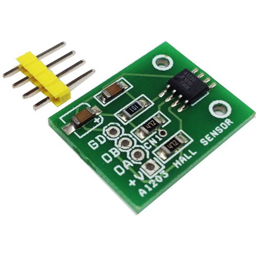
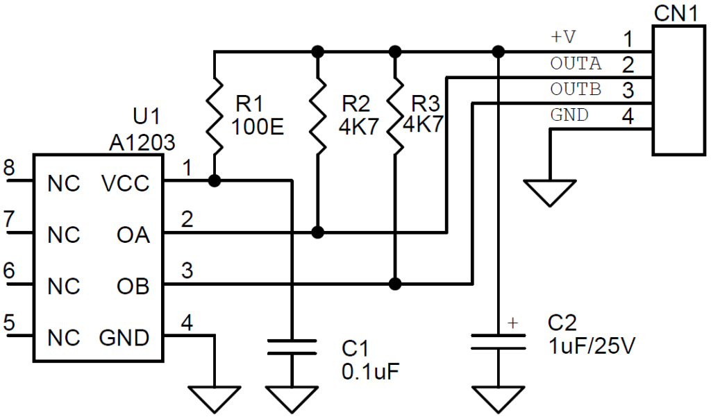
The A1230 is a dual-channel, bipolar switch with two Hall-effect sensing elements, each providing a separate digital output for speed and direction signal processing capability. The Hall elements are photo lithographically aligned to better than 1 µm. maintaining accurate mechanical location between the two active Hall elements eliminates the major manufacturing hurdle encountered in fine-pitch detection applications. The A1230 is a highly sensitive, temperature stable magnetic sensing device ideal for use in ring magnet based, speed and direction systems located in harsh automotive and industrial environments.
The A1230 monolithic integrated circuit (IC) contains two independent Hall-effect bipolar switches located 1 mm apart. The digital outputs are out of phase so that the outputs are in quadrature when interfaced with the proper ring magnet design. This allows easy processing of speed and direction signals. Extremely low-drift amplifiers guarantee symmetry between the switches to maintain signal quadrature. The Allegro patented, high-frequency chopper-stabilization technique cancels offsets in each channel providing stable operation over the full specified temperature and voltage ranges.
Dual-Channel Quadrature Hall-Effect Bipolar Switch Module for Magnetic Encoder – [Link]
The A1230 is a dual-channel, bipolar switch with two Hall-effect sensing elements, each providing a separate digital output for speed and direction signal processing capability. The Hall elements are photo lithographically aligned to better than 1 µm. maintaining accurate mechanical location between the two active Hall elements eliminates the major manufacturing hurdle encountered in fine-pitch detection applications. The A1230 is a highly sensitive, temperature stable magnetic sensing device ideal for use in ring magnet based, speed and direction systems located in harsh automotive and industrial environments.
The A1230 monolithic integrated circuit (IC) contains two independent Hall-effect bipolar switches located 1 mm apart. The digital outputs are out of phase so that the outputs are in quadrature when interfaced with the proper ring magnet design. This allows easy processing of speed and direction signals. Extremely low-drift amplifiers guarantee symmetry between the switches to maintain signal quadrature. The Allegro patented, high-frequency chopper-stabilization technique cancels offsets in each channel providing stable operation over the full specified temperature and voltage ranges.
Additionally, the high-frequency chopping circuits allow an increased analog signal-to-noise ratio at the input of the digital comparators internal to the IC. As a result, the A1230 achieves industry-leading digital output jitter performance that is critical in high performance motor commutation applications. An on-chip low dropout (LDO) regulator allows the use of this device over a wide operating voltage range. Post-assembly factory programming at Allegro provides sensitive switch points that are symmetrical between the two switches.
Bipolar Switch Applications and Working from Allegro Micro
There are four general categories of Hall-effect IC devices that provide a digital output: unipolar switches, bipolar switches, omnipolar switches, and latches. Bipolar switches are described in this application note. Similar application notes on unipolar switches, omnipolar switches, and latches are provided on the Allegro™ website.
Bipolar sensor ICs are designed to be sensitive switches. (Note that the term “bipolar” refers to magnetic polarities, and is not related to bipolar semiconductor chip structures.) A bipolar switch has consistent hysteresis, but individual units have switchpoints that occur in either relatively more positive or more negative ranges. These devices find application where closely-spaced, alternating north and south poles are used, resulting in minimal required magnetic signal amplitude, ΔB, because the alternation of magnetic field polarity ensures switching, and the consistent hysteresis ensures periodicity.
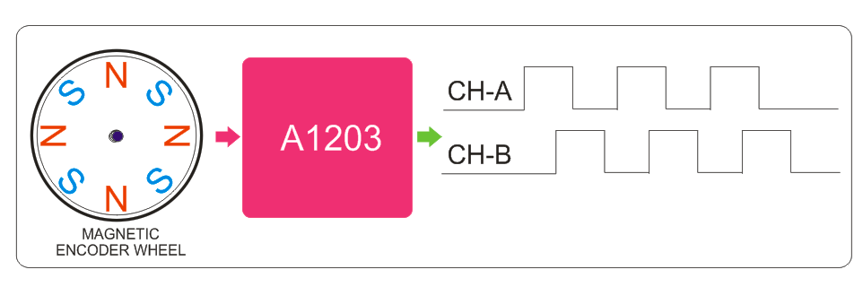
Applications for detecting the position of a rotating shaft, such as in a brushless dc motor (BLDC) are shown in figure 1. The multiple magnets are incorporated into a simple structure referred to as a “ring magnet,” which incorporates alternating zones of opposing magnetic polarity. The IC package adjacent to each ring magnet is the Hall bipolar switch device. When the shaft rotates, the magnetic zones are moved past the Hall device. The device is subjected to the nearest magnetic field and is turned-on when a south field is opposite, and turned-off when a north field is opposite. Note that the branded face of the device is toward the ring magnet.
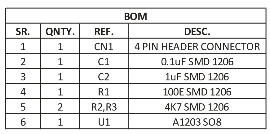
Features
It Provides Dual A & B Channel Like optical Encoder
Simple Module help to make Magnetic Encoder for Motion Control application
Supply 5V DC
TTL Output
Two matched Hall-effect switches on a single substrate
1 mm Hall element spacing
Superior temperature stability and industry-leading jitter performance through use of advanced chopper stabilization topology Integrated LDO regulator provides 3.3 V operation
Integrated ESD protection from outputs and VCC to ground
High-sensitivity switch points
Robust structure for EMC protection
Solid-state reliability
Reverse-battery protection on supply and both output pins
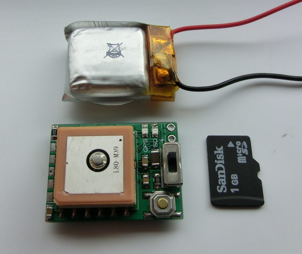
pinko @ blog.exrockets.com has build a mini GPS data logger based on PIC18F25J11 microcontroller.
Based on my first GPS data logger I made a new version which is even smaller than the initial design and should be able to fit in any rocket, RC model etc. The new GPS data logger uses micro-SD card and 3.7v LIPO battery as power source. The board was also optimized and the new size is 20mm x 27mm – less than a standard SD card as you can see on the picture to the right.
MINI PIC GPS DATA LOGGER WITH MICRO-SD CARD – [Link]


 Airborne particles with a diameter of less than 10 microns pose a large risk, they can travel deeply into the respiratory system, causing a variety of cardiovascular and respiratory diseases. Combustion (e.g. burning wood; automobiles) can generate particles less than 2.5 microns in diameter. Between 2.5 and 10 microns are particles such as dust, pollen, and mold. (More information about particulate matter can be found