How to Setup an LCD Touchscreen on the Raspberry Pi

circuitbasics.com has a tutorial on how to setup a LCD screen for Raspberry Pi.

In this tutorial, I’ll walk you through the process of installing an LCD touchscreen on the Raspberry Pi, step by step. Many LCD touchscreens for the Raspberry Pi include an image file that you can write to your SD card and get up and running pretty quickly.

How to Setup an LCD Touchscreen on the Raspberry Pi – [Link]

CMOS-TTL QUADRATURE ENCODER USING LS7084

The quadrature LS7084 Module is a CMOS quadrature clock converter. Quadrature clocks derived from optical or magnetic encoders, when applied to the A and B inputs of the LS7084 are converted to strings of a Clock and an Up/down direction control. These outputs can be interfaced directly with standard Up/Down counters for direction and position sensing of the encoder.

Features

  • Supply 5V DC
  • +4.5V to +10V operation (VDD – VSS)
  • On Board Power LED
  • J1 Encoder pulse multiplication ( Jumper JL Close =1X, Jumper JH Close = X4)
  • Header Connector for Encoder Interface
  • X1 and X4 mode selection
  • Programmable output clock pulse width
  • On-chip filtering of inputs for optical or magnetic encoder applications.
  • TTL and CMOS compatible I/Os
  • Up to 16MHz output clock frequency

CMOS-TTL QUADRATURE ENCODER USING LS7084 – [Link]

CMOS-TTL QUADRATURE ENCODER USING LS7084

The quadrature LS7084 Module is a CMOS quadrature clock converter. Quadrature clocks derived from optical or magnetic encoders, when applied to the A and B inputs of the LS7084 are converted to strings of a Clock and an Up/down direction control. These outputs can be interfaced directly with standard Up/Down counters for direction and position sensing of the encoder.

J1 Jumper input selects between x1 and x4 modes of operation. A high level selects x4 mode and a low-level selects the x1 mode. In x4 mode, an output pulse is generated for every transition at either A or B input. In x1 mode, an output pulse is generated in one combined A/B input cycle.

Resistor R7-RBIAS (Pin 1) Input for external component connection. A resistor connected between this input and VSS adjusts the output clock pulse width (Tow). For proper operation, the output clock pulse width must be less than or equal to the A, B pulse separation (TOW £ TPS).

Note: Check Graph for R7- Bias Selection

Features

  • Supply 5V DC
  • +4.5V to +10V operation (VDD – VSS)
  • On Board Power LED
  • J1 Encoder pulse multiplication ( Jumper JL Close =1X, Jumper JH Close = X4)
  • Header Connector for Encoder Interface
  • X1 and X4 mode selection
  • Programmable output clock pulse width
  • On-chip filtering of inputs for optical or magnetic encoder applications.
  • TTL and CMOS compatible I/Os
  • Up to 16MHz output clock frequency

Schematic

Parts List

Diagram

Bias Selection

LS7084 Datasheet

LTC4380 Overvoltage Protection

Thomas Scherer @ elektormagazine.com writes:

When it comes to protecting sensitive circuitry from potentially damaging over-voltage spikes and supply surges we usually resort to networks of coils, capacitors, resistors and suppression diodes to iron out the transients. The LTC4380 low quiescent current surge stopper IC from Linear Technology goes about it in a different way; it looks out for over-voltage nasties and switches a fast N-channel external series-connected MOSFET to limit the surge. The chip is just 3 mm square and draws very little quiescent current.

LTC4380 Overvoltage Protection – [Link]

SensorTile, An Accurate Development Kit For Biometric Wearables

Valencell, a biometric wearable sensor technology company, in partnership with STMicroelectronics, an electronics and semiconductor manufacturer, announced a new highly accurate and scalable development kit for biometric wearables. The kit combines ST’s compact SensorTile turnkey multi-sensor module with Valencell’s Benchmark biometric sensor system.

The SensorTile is a tiny IoT module (13.5mm x 13.5mm) that features a powerful STM32L4 microcontroller, a Bluetooth Low Energy (BLE) chipset, a wide spectrum of high-accuracy motion and environmental MEMS sensors (accelerometer, gyroscope, magnetometer, pressure, temperature sensor), and a digital MEMS microphone.

The on-board low-power STM32L4 microcontroller makes it work as a sensing and connectivity hub for developing firmware and shipping in products such as wearables, gaming accessories, and smart-home or IoT devices.

Key Features:

  • FCC (ID: S9NSTILE01) and IC (IC: 8976C-STILE01) certified
  • Included in the development kit package:
    • SensorTile module
    • SensorTile expansion Cradle board equipped with audio DAC, USB port, STM32 Nucleo, Arduino UNO R3 and SWD connector
    • SensorTile Cradle with battery charger, humidity and temperature sensor, SD memory card slot, USB port and breakaway SWD connector
    • 100 mAh Li-Ion battery
    • Plastic box for housing the SensorTile cradle and the battery
    • SWD programming cable
  • Software libraries and tools
    • STSW-STLKT01: SensorTile firmware package that supports sensors raw data streaming via USB, data logging on SDCard, audio acquisition and audio streaming. It includes low level drivers for all the on-board devices
    • BLUEMICROSYSTEM1 and BLUEMICROSYSTEM2: STM32Cube expansion software package, supporting different algorithms tailored to the on-board sensors
    • FP-SNS-ALLMEMS1 and FP-SNS-MOTENV1: STM32 ODE functional packs
    • ST BlueMS: iOS and Android demo Apps
    • BlueST-SDK: iOS and Android Software Development Kit
    • Compatible with STM32 ecosystem through STM32Cube support

“Valencell’s Benchmark solution leverages the high accuracy of ST’s MEMS sensor technology along with SensorTile’s miniature form factor, flexibility, and STM32 Open Development Environment-based ecosystem,” said Tony Keirouz, Vice President Marketing and Applications, Microcontrollers, Security, and Internet of Things, STMicroelectronics. “Combined, SensorTile and Benchmark enable wearable makers to quickly and easily develop the perfect product for any application that integrates highly accurate biometrics.”

Integrating ST’s SensorTile development kit with Valencell’s Benchmark sensor technology simplifies the prototyping, evaluation, and development of innovative wearable and IoT solutions. That’s done by delivering a complete Valencell PerformTek technology package, ready for immediate integration and delivery into wearable devices. The collaboration with ST expands on previous work that incorporated the company’s STM32 MCUs and sensors into Valencell’s Benchmark sensor system.

“Working with ST has allowed us to bring together the best of all sensors required to support the most advanced wearable use cases through our groundbreaking Benchmark sensor system,” said Dr. Steven LeBoeuf, president and co-founder of Valencell.

The kit is in volume production and is available for about $80. You can order it and get more information and technical details through the official page.

Source: ElectronicSpecifier

RGBdigit clock

by Lucky @ elektormagazine.com build a LED display clock able to display temperature, humidity and air pressure. He writes:

What do you do when you want to design ‘something’ with a vintage or modern display? A clock of course, and this is our first design with RGBDigits: multi-colour 7-segment displays. With a BME280 breakout board attached it will also display temperature, humidity and air pressure. The clock is controlled by an ESP12 module, which makes it possible to synchronise the clock with an internet time server, change the clock settings from any mobile device or computer in the network, or transmit sensor data via Wi-Fi.

RGBdigit clock – [Link]

Arduino Tutorial: Menu on a Nokia 5110 LCD Display Tutorial

In this easy Arduino Tutorial educ8s.tv is going to show us how to create a Menu on a Nokia 5110 LCD display.

This is the project we are going to build. In the display a simple menu appears, and with the help of three buttons I can navigate up, or down and select a menu item. Let’s select the first option. As you can see a new a UI screen is displayed and by pressing the up and down buttons we can change the contrast of the display. If we press the middle button again, we go back to the main UI screen. If we now select the second menu item and press the middle button we can turn the backlight of the display on or off. Lastly if we navigate to the last menu item we can reset the settings for the display to the default values. Of course this is just a demonstration project, you can modify it to build your own more complex menus if you wish. Let’s now see how to build this project.

Arduino Tutorial: Menu on a Nokia 5110 LCD Display Tutorial [Link]

High Performance Stereo Audio Amplifier using LM3886

The LM3886 is a high-performance audio power amplifier capable of delivering 68W of continuous average power to a 4Ω load and 38W into 8Ω with 0.1% THD+N from 20Hz–20kHz.

The performance of the LM3886, utilizing its Self Peak Instantaneous Temperature (°Ke) (SPiKe) protection circuitry, puts it in a class above discrete and hybrid amplifiers by providing an inherently, dynamically protected Safe Operating Area (SOA). SPiKe protection means that these parts are completely safeguarded at the output against overvoltage, under voltage, overloads, including shorts to the supplies, thermal runaway, and instantaneous temperature peaks.

The LM3886 maintains an excellent signal-to-noise ratio of greater than 92dB with a typical low noise floor of 2.0µV. It exhibits extremely low THD+N values of 0.03% at the rated output into the rated load over the audio spectrum, and provides excellent linearity with an IMD (SMPTE) typical rating of 0.004%.

Note : Amplifier Requires a Large Size Heat sink

High Performance Stereo Audio Amplifier using LM3886 – [Link]

Open Source Meets Hardware: Open Processor Core

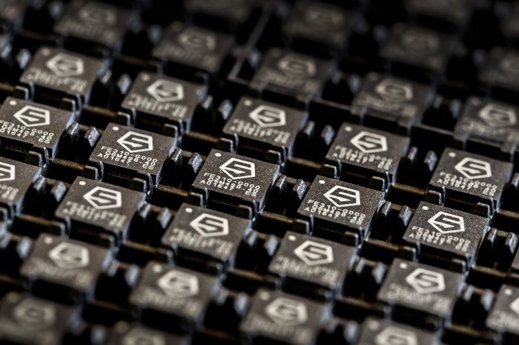
SiFive, the first fabless provider of customized, open-source-enabled semiconductors, had recently announced the availability of its Freedom Everywhere 310 (FE310) system on a chip (SoC), the industry’s first commercially available SoC based on the free and open RISC-V instruction set architecture.

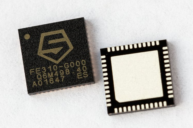
The Freedom E310 (FE310) is the first member of the Freedom Everywhere family of customizable SoCs. Designed for microcontroller, embedded, IoT, and wearable applications, the FE310 features SiFive’s E31 CPU Coreplex, a high-performance, 32-bit RV32IMAC core. Running at 320+ MHz, the FE310 is among the fastest microcontrollers in the market. Additional features include a 16KB L1 Instruction Cache, a 16KB Data SRAM scratchpad, hardware multiply/divide, a debug module, flexible clock generation with on-chip oscillators and PLLs, and a wide variety of peripherals including UARTs, QSPI, PWMs, and timers. Multiple power domains and a low-power standby mode ensure a wide variety of applications can benefit from the FE310.

Furthermore, SiFive launched an open source low-cost HiFive1 software development board based on FE310. As part of this availability, SiFive also has contributed the register-transfer level (RTL) code for FE310 to the open-source community.

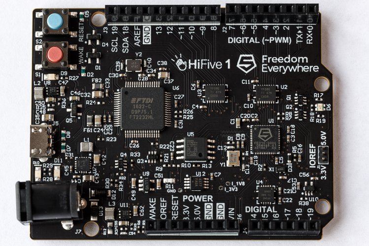
The Arduino compatible HiFive1 was live on a crowdfunding campaign on Crowdsupply  and the board reached around $57,000 funding. Check this video to know more about HiFive1:

SiFive is now fulfilling a dream of a lot of developers: a custom silicon designed just for you! With the RTL code open, chip designers are now able to customize  their own SoC on top of the base FE310 by accessing the open source files provided on Github. But don’t worry, even if you don’t have the expertise needed to develop your own core, SiFive is offering a new service called “ chips-as-a-service” that can customize the FE310 to meet your unique needs. All you need is to register here dev.sifive.com, try out your ideas and finally contact the company to finalize the design of your new chip.

This service has completely a new business model for silicon chips businesses, and SiFive is willing to establish a “chip design factory” that can handle 1000 new chip designs a year. It is said that SiFive can start manufacturing the cusomized MCUs in less than 6 months after making sure that each use case is compatible with the Freedom E310 core.

“We started with this revolutionary concept — that instruction sets should be free and open – and were amazed by the incredible rippling effect this has had on the semiconductor industry because it provided a viable alternative to what was previously closed and proprietary,” said Krste Asanovic, co-founder and chief architect, SiFive. “In the few short months since we’ve announced the Freedom Platforms, we’ve seen a tremendous response to our vision of customizable SoCs. The FE310 is a major step forward in the movement toward open-source and mass customization, and SiFive is excited to bring the opportunity for innovation back into the hands of system architects.”

Opening the source of processors’ core has its pros and cons for SiFive. A new business model is assigned to SiFive due to the “chips-as-a-service” feature but in the same time it will open up some new ventures for smaller companies and hardware manufacturers to compete with the market dominating companies. Open source MCUs will bring a lot of updates to the hardware development scene and will pave the way for a whole new business of customized chip design provided by talented hardware system developers and architects.

To know more about the custom design feature visit the developers section of SiFive dev.sifive.com. Documentation of the SiFive new chip is available here and also source codes and files of the RTL code are provided at Github.

SMART.IO, An Affordable Remote Control for Embedded Designs

Creating a smartphone application for your embedded products may be a high-cost process that consumes time and efforts. ImageCraft, a producer of high quality low cost embedded system tools, had developed “Smatr.IO” as a very cheap alternative solution that allows you to add a friendly user interface to any embedded project.

Smart.IO is a toolkit that helps you to create a compatible application with your product without the need of any experience in wireless technology or app development. It uses BLE (Bluetooth Low Energy) and it doesn’t require an Internet connection or data plan.

Smart.IO consists of three parts:

  • A Small Chip Module compatible with any microcontroller.
  • A Software API for creating Graphical User Interface (GUI) objects.
  • A Programmable Smartphone App that requires only a Bluetooth connection to use.

There is no need to write any wireless code, or write an app. All you need is to add the Smart.IO chip to your existing microcontroller-based design, then use the API to create GUI objects in your firmware.

The Smart.IO Chip Module

The Smart.IO chip module is only 25mmx14mm. It has a 10-pin headers which are easy to solder onto your PCB, or use in a prototype system. It interfaces with your host microcontroller using SPI pins, plus extra pins for interrupts for data notification. Smart.IO draws very little power, typically about 100mA, and much less during standby mode.

If you are an Arduino user, ImageCraft will provide an Arduino-compatible shield that comes with a Smart.IO chip module, so that Arduino users can start using it immediately.

The Smart.IO API

The API functions allow you to create GUI objects and to modify their values. A simple callback mechanism notifies your firmware of input changes. The API code will run in the Smart.IO chip firmware, and the host MCU only runs the API interface layer code, so it will not use the host MCU resources.

The Programmable Smart.IO App

The GUI elements incorporate solid, current user interface principles. The UI will look and work exactly the same way across all iOS devices, from the iPhone 5 to iPhone 7+, and all iPad devices, including the iPad Pro. An Android friendly UI is planned for Spring.

There is also a customized version of the app specific to your product and branding for an inexpensive one-time licensing fee including customized app logo and name and security key to ensure your product will only work with your app.

Smart.IO Security

Secret key encryption is used to ensure secure pairing of the device and customized app. As Smart.IO does not use the Internet, there is no risk of your device being used for DDOS or other types of attacks through the use of Smart.IO.

Through the Kickstarter campaign, Smart.IO reached about $9,500 and pre-ordering is still open here. ImageCraft will start work on the Android version of the programmable app and set up a forum for Smart.IO users. A use case example of Smart.IO is available on the official page.

TOP PCB Companies