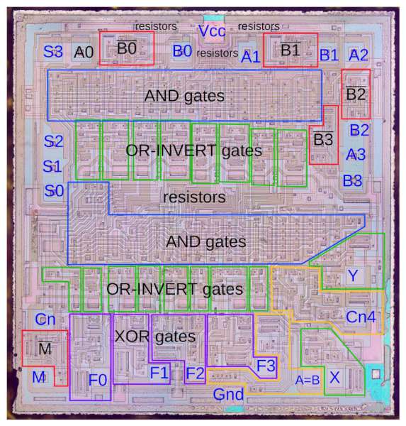
A detailed die photos and reverse engineering of the 74181 ALU chip by Ken Shirriff:
What’s inside a TTL chip? To find out, I opened up a 74181 ALU chip, took high-resolution die photos, and reverse-engineered the chip.1 Inside I found several types of gates, implemented with interesting circuitry and unusual transistors. The 74181 was a popular chip in the 1970s used to perform calculations in the arithmetic-logic unit (ALU) of minicomputers. It is a moderately complex chip containing about 67 gates and 170 transistors3, implemented using fast and popular TTL (transistor-transistor logic) circuitry.
Inside the 74181 ALU chip: die photos and reverse engineering – [Link]
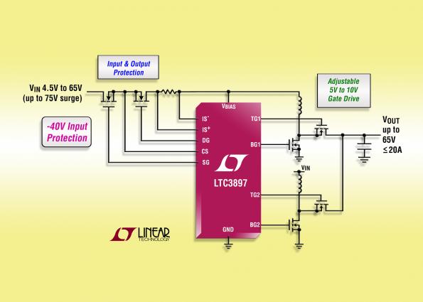
LTC3897 is a multiphase synchronous boost DC/DC controller with input surge stopper and ideal-diode controller. The boost controller drives two N-channel power MOSFET stages out-of-phase to reduce input and output capacitor requirements, enabling the use of smaller inductors versus the single-phase equivalent. By Graham Prophet @ edn-europe.com:
Synchronous rectification increases efficiency, reduces power loss and eases thermal requirements. The input surge stopper, with adjustable clamp voltage, controls the gate of an external N-channel MOSFET to protect against high input voltage transients of greater than 100V and provides inrush current control, overcurrent protection and output disconnect. The integrated ideal diode controller drives another N-channel MOSFET for reverse input voltage protection and voltage holdup or peak detection.
Multiphase, 60V synchronous boost controller peaks at 97% – [Link]
T A Babu @ edn.com discuss about a protection circuit for boost converters.
Boost converters are particularly susceptible to output shorts as there is a DC path from input to output. Usually a fuse, resettable or non-resettable, protects the system, but it is not always accurate or fast enough.
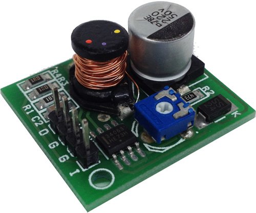
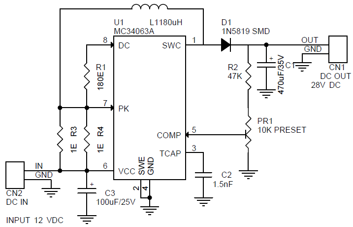
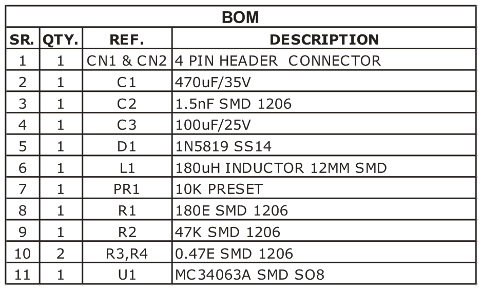
The Step-Up DC-DC Converter project provides 28V, 175mA output with input of 12V DC. The MC34063A IC is heart of the project from On semiconductor. The MC33063A is a monolithic control circuit containing the primary functions required for DC-DC converters. This device consist of an internal temperature compensated reference, comparator, controlled duty cycle oscillator with an active current limit circuit, driver and high current output switch. This IC specially designed to be incorporated step-down, step-up, and voltage-inverting applications with minimum number of external components.
Features
Input 12V DC
Output 28V, 175mA
Output Voltage Adjustable By On-board Preset
Header Connector for Output/Input Connections
Low Standby Current
Step Up DC-DC Converter – 12V TO 28V DC 175mA – [Link]
The Step-Up DC-DC Converter project provides 28V, 175mA output with input of 12V DC. The MC34063A IC is heart of the project from On semiconductor. The MC33063A is a monolithic control circuit containing the primary functions required for DC-DC converters. This device consist of an internal temperature compensated reference, comparator, controlled duty cycle oscillator with an active current limit circuit, driver and high current output switch. This IC specially designed to be incorporated step-down, step-up, and voltage-inverting applications with minimum number of external components.
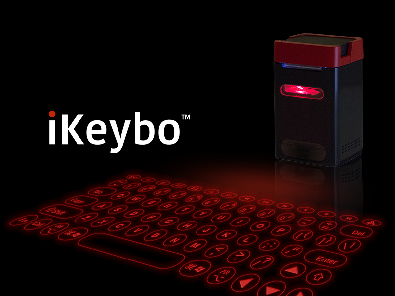
Serafim is a company of some talents and experts in optoelectronics industry, and it aims to offer affordable, useful, and cool consumer electronics for a better computing experience. The latest amazing product by Serafim is: iKeybo!
iKeybo is a virtual projection multilingual keyboard that can turn any flat surface into a keyboard. iKeybo can work as a piano too.
Check this video to see iKeybo in action:
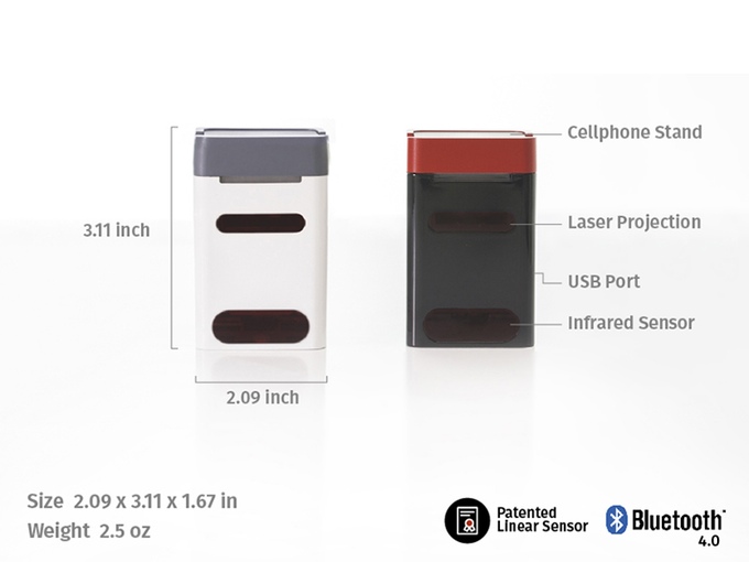
iKeybo uses a non-contact technology and has 90Hz frame rate. It turns your 5 inch display into 12 in a surface since the projection surface is 268*105mm. The keyboard consists of 78 keys where other competitors only have 66. It has a instant reaction around 11.11ms what makes it more convenient while using.You can use iKeybo with you PC, mobile devices and tablets since it works via Bluetooth and USB.
For developers, a SDK for iOS and Android is available! It supports all functions of touch screen which include single tap, double tap, rotate, press and drag, press and hold. Install the framework and make connections with your apps.
It differentiates from other laser projection keyboard because it implements a new patented technology that uses camera sensor and double linear sensors for faster calculation speed and less energy.
“What distinguish iKeybo from traditional projection keyboards is that it is the world’s first laser projection “piano” that allows users to create music instantly with piano, guitar, bass, or drums. When not in use, iKeybo can also serves as an external charger to power up devices with 10 hours of battery life. Its cellphone stand design is also perfect for desk or table to watch movies or start live streaming.“ – iKeybo team
iKeybo Features
4 Language Layouts you can choose from 4 different languages keyboard layouts (English, Spanish, Arabic, and Chinese) to type the language special characters that you need. You can’t add more language layouts to your iKeybo because each layout projection needs a different optical lens. Once you select a language edition or a bilingual one it will be fixed.
4 Musical Instruments with iKeybo you can play piano, guitar, bass and drums! Check this piano demo video:
Round Key Designs a special design to make it easier for typing. Other competitors use square keys with no space in between that make it possible to do a lot of typos.
Portable Charger & Cell Phone Stand iKeybo also serves as an external charger to power up your devices with 10 hours of battery life. You can also use it as your cellphone stand to turn your mobile device into a computer within just a second.
iKeybo is not the first optoelectronics product by parent company Serafim. Check this page to know more about its products.
iKeybo is now live on a Kickstarter campaign and still has 10 days to go! You can pre-order your iKeybo with one language layout and piano for $89 and also you can get a bilingual iKeybo for $99. More information are available at the campaign page.
If you want to take a timelapse with your camera, it may be helpful to use an intervalometer. It is an attachment or facility on a camera that operates the shutter regularly at set intervals over a period, in order to take timelapse series or take pictures after a set delay.
Daniel Knezevic had developed a custom made intervalometer for DSLR cameras. Dintervalometer (Deni’s intervalometer) enables cameras to shoot time lapses and allows shutter speeds longer than the 30s.
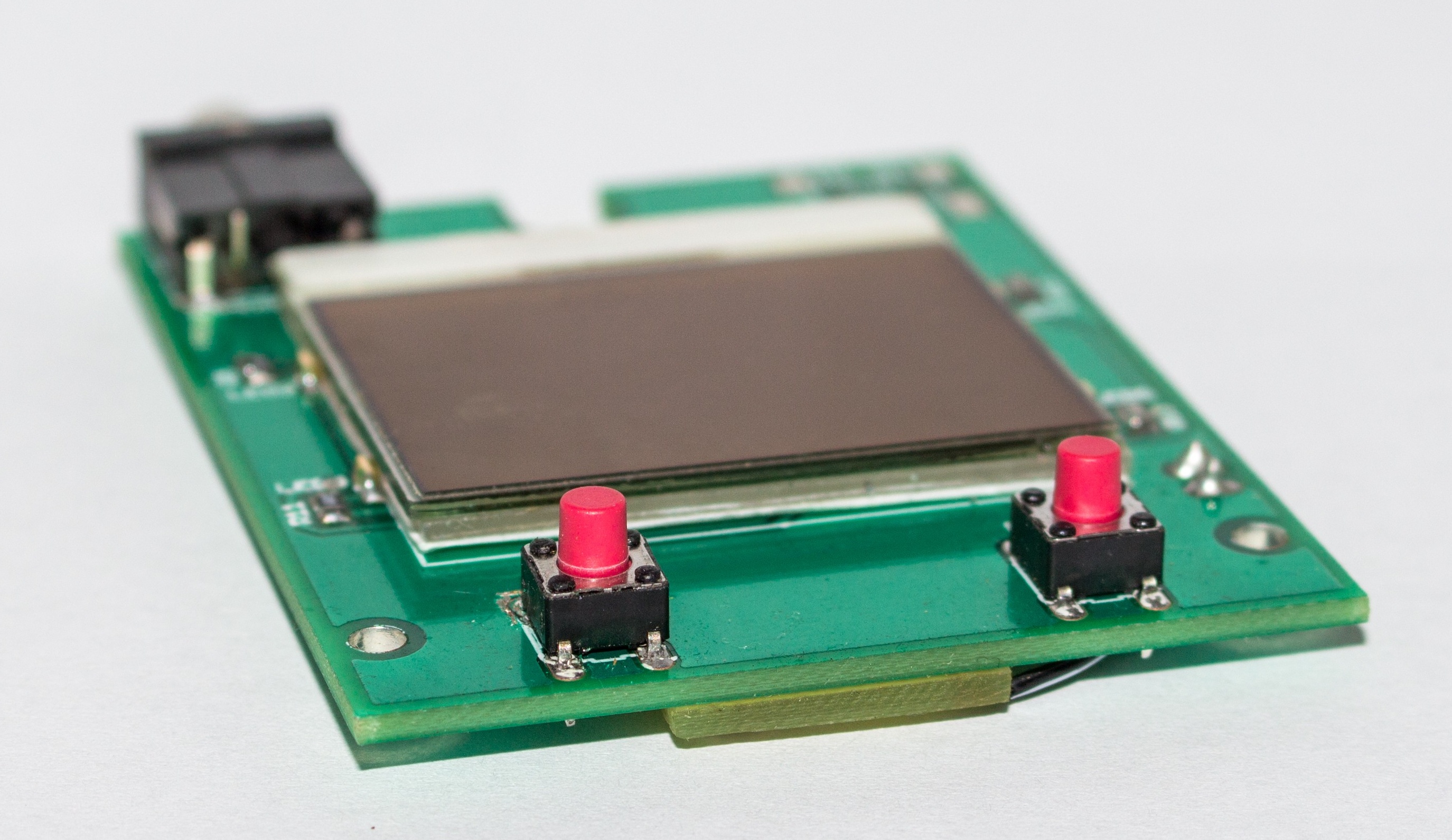
The Dintervalometer is built with an Atmega328P clocked at 10MHz, a PCD8544 84×48 pixel monochrome LCD display with a backlight, a 3.5mm male jack connector, and two tactile push buttons all combined together on a small PCB.
Dintervalometer Features
Intervalometer: It is used for time-lapse photography. It controls how often, how long and how many shots are taken.
Bulb mode: It allows to take time exposures longer than 30s.
Backlight
Charging via USB
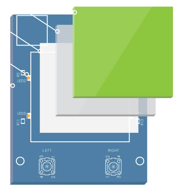
The Display & Backlight
The PCD8544 LCD display can be powered using 3V3 and it draws very small amounts of power (around 200uA) making it extremely good for use in battery powered devices. It is typically used in Nokia5110/3310 phones, and it interfaces to microcontrollers through a serial bus interface (SPI).
A custom made backlight were designed to allow using the Dintervalometer in the dark without an additional lamp. It operates like a backlight of a cell phone: it is active for 10 seconds when the user presses a button or the Dintervalometer finishes some job.
The backlight consists of these materials:
A sheet of white paper
A piece of transparent plastic
A double-sided tape
The first layer of the backlight is a sheet of white paper. Its main function is to reflect the light of the LEDs. Then it comes the piece of transparent plastic. The top of the plastic is sanded with a fine sandpaper to diffuse the light. Finally, the LCD comes on the top. The layers are glued together with a double-sided tape.
Powering & Charging
Dintervalometer’s circuit is powered using a LiPo battery and a very low drop 3V3 voltage regulator (TPS79933). A MAX1555 Li+ battery charger IC is used to charge the battery, which also can be powered via USB.
To prevent the over-discharge of the LiPo battery, Dintervalometer monitors and measures the battery voltage every 60 seconds. The user can always see the current status of the battery on the LCD. When the battery reaches the critical voltage, a “Low battery” notification will be shown, then the device will turn off.
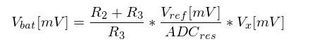
The voltage measuring process is done using a voltage divider and AVRs internal 1V1 voltage reference.
The following equation is used to measure the battery voltage in mV, with the known values R2=10k, R3=3k3, Vref=1100mV, ADCres=1024.
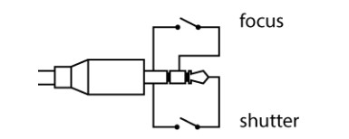
Controlling The Camera
Using the 3.5mm male jack connector, the Dintervalometer will trigger the camera to focus and to take a picture. The jack consists of three wires: ground, focus and shutter.
To focus the camera, the focus wire has to be connected to the ground. To release the camera both wires have to be connected to the ground. Dintervalometer is tested with Canon EOS 700D. It has a jack plug for remote shuttering.
The Software
The software is written in C and compiled with avr-gcc. It is divided into 6 logical modules:
TIMER: Initializes Timer1 and provides an interrupt based delay function.
BATTERY: Initializes ADC to read the battery voltage.
BACKLIGHT: Functions are used to control the backlight (initialize and update).
GPIO: Initializes IO ports for buttons, camera output, battery charger status indication, auto cut off control output.
LCD: It represents the pcd8544 LCD driver, it is reusable code for other projects. The driver provides the API to initialize, control, and print text on the LCD.
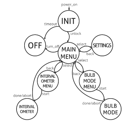
STATE: The state machine is implemented by using function pointers. Each menu state has three basic operations; show data on LCD, wait for user input, update backlight and battery status, and handle button presses/holds.
State Machine Diagram
Dintervalometer Sources
This project is published on hackady.io. Daniel had shared all the source designs and scripts online, so you can get it on its Github repository.
Born in 2014 from the simple idea of making 3D printing accessible for everyone, Filippo Moroni and Pietro Gabriele worked on new technology to develop a high quality 3D printer that was affordable and easy to use. Their goal was to make the most diffused printer in the world and to develop a worldwide community around it. After 2 years of hard work, ONO has developed and grown into the first 3D printer of its class. ONO is the first ever smartphone-powered 3D printer that depends on your smartphone screen resolution in its printed outputs.
Similar to DLP (Digital Light Processing) resin printers, ONO needs light to harden the resins. But instead of using an embedded source of light, it uses the light of your smartphone screen to power the operation. Thanks to the customized patented resins ONO uses, they can react perfectly to white light coming from your phone, thus there’s no need for ultra violet light that is used for resin printers. All you need to do is to place your mobile on the phone pad and ONO will do the rest.
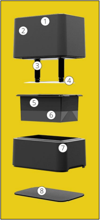
ONO has the following components:
LED interface – The logo on the top of the printer flashes to show the status of the print
Motor housing – The top part of the printer which controls the raising of the build plate
Z-axis actuators – Drive gears connected to the motor and the build plate
Build plate – Aluminum plate where the part adheres
Resin tank – Removable tank where resin is poured prior to printing
Printing film – Thin, clear film which seals the resin tank
Adjustable base – The base can be raised or lowered so that the phone screen will sit flat against the printing film.
Phone pad – A soft pad that helps level phones with protruding cameras
The affordable $99 3D printer is portable and can be charged using any USB charger whether connected to wall plugs or a power bank. You can clean ONO easily thanks to the removable resin tank and the printing films.
ONO has the following specifications:
Printer Dimensions: 180 x 128 x 185 mm – 7.0 x 5.0 x 7.3 in
Printing Volume: 124 x 72 x 52 mm – 4.8 x 2.8 x 2.0 in
Phone compatibility: Any phone with a screen size below 5.8”
Accuracy: Up to 42 micron XY resolution, Up to 100 micron Z resolution
(XY resolution depends on the resolution of the phone screen.)
Printing Speed: 12 mm per hour
It’s a simple process, after downloading the app you have to choose the design to be printed and then plug in through the headphone jack. Finally fill the resin tank with the resin you prefer. ONO is providing multiple kinds of resins for different uses: solid, flexible, translucent, castable and clear! The $15 resin bottle is said to be able to bring out around 10 simple 3D printed objects, and the amazing thing is that unused resin can be recycled for future prints!
“We believe 3D printing should be accessible to everyone. This is why we set out to design ONO, the first ever smartphone 3D printer.” – ONO team
You can check this video by Adafruit to know more about ONO during World Maker Faire 2016 featuring Giacomo Fornasini:
ONO is a rebrand of OLO, the first edition of the printer that was live on Kickstarter one year ago. More details about ONO can be found at the official website where you can sign up on its newsletter to be updated and to know when ONO will be available to buy.
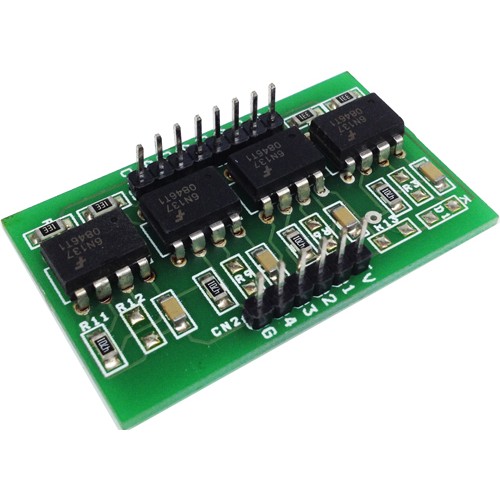
4 Channel Opto isolated board has been designed around 6N137 Opto-coupler, the 6N137 optocoupler is designed for use in high-speed digital interfacing applications that require high-voltage isolation between the input and output. Applications include line receivers, microprocessors or computer interface, digital programming of floating power supplies, motors, and other control systems.
The 6N137 high-speed optocoupler consists of a GaAsP light-emitting diode and an integrated light detector composed of a photodiode, a high-gain amplifier, and a Schottky-clamped open-collector output transistor. An input diode forward current of 5 milliamperes will switch the output transistor low, providing an on-state drive current of 13 milliamperes (eight 1.6-milliampere TTL loads).
4 Channel Opto-Isolated Module Using High Speed 6N137 Optocoupler – [Link]
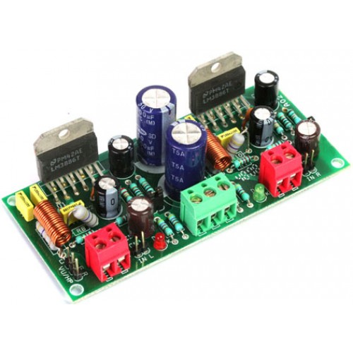
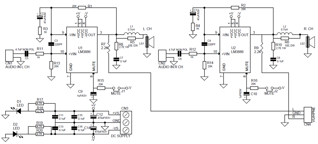
The LM3886 is a high-performance audio power amplifier capable of delivering 68W of continuous average power to a 4Ω load and 38W into 8Ω with 0.1% THD+N from 20Hz–20kHz.
The performance of the LM3886, utilizing its Self Peak Instantaneous Temperature (°Ke) (SPiKe) protection circuitry, puts it in a class above discrete and hybrid amplifiers by providing an inherently, dynamically protected Safe Operating Area (SOA). SPiKe protection means that these parts are completely safeguarded at the output against overvoltage, under voltage, overloads, including shorts to the supplies, thermal runaway, and instantaneous temperature peaks.
The LM3886 maintains an excellent signal-to-noise ratio of greater than 92dB with a typical low noise floor of 2.0µV. It exhibits extremely low THD+N values of 0.03% at the rated output into the rated load over the audio spectrum, and provides excellent linearity with an IMD (SMPTE) typical rating of 0.004%.
Note : Amplifier Requires a Large Size Heat sink
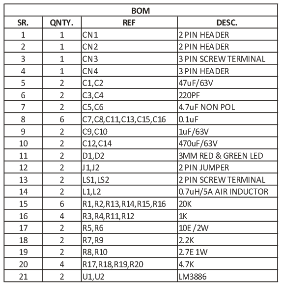
Features
68W Cont. Avg. Output Power into 4Ω at VCC = ±28V
38W Cont. Avg. Output Power into 8Ω at VCC = ±28V
50W Cont. Avg. Output Power into 8Ω at VCC = ±35V
135W Instantaneous Peak Output Power Capability
Signal-to-Noise Ratio ≥ 92dB
An Input Mute Function ( J1 & J2 Jumper)
Output Protection from a Short to Ground or to the Supplies via Internal Current Limiting Circuitry
Output Over-Voltage Protection against Transients from Inductive Loads
Supply Under-Voltage Protection, not Allowing Internal Biasing to Occur when |VEE| + |VCC| ≤ 12V, thus Eliminating Turn-On and Turn-Off Transients


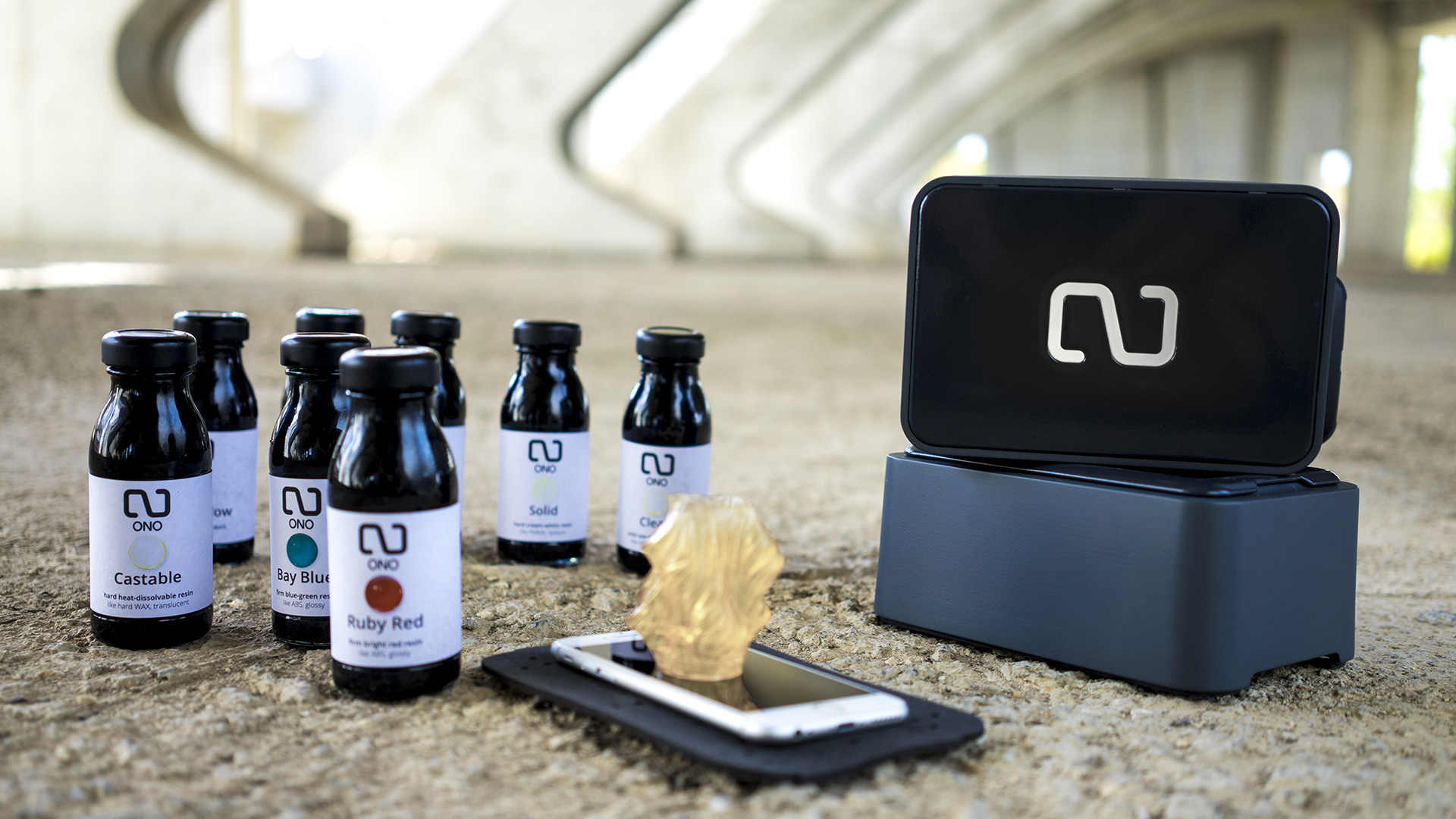
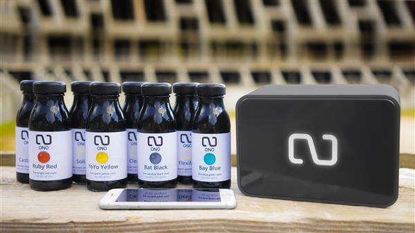 e printed and then plug in through the headphone jack. Finally fill the resin tank with the resin you prefer. ONO is providing multiple kinds of resins for different uses: solid, flexible, translucent, castable and clear! The $15 resin bottle is said to be able to bring out around 10 simple 3D printed objects, and the amazing thing is that unused resin can be recycled for future prints!