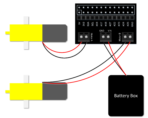
Here is a nice tutorial @ raspberrypi.org on how to control a DC motor using Python.
In this guide, you’ll be controlling two motors from your Raspberry Pi using Python on the desktop. First, it’s best just to learn how to control the motor. Then, once you have it working, you could easily use your code to drive a Raspberry Pi-powered robot by detaching the monitor, mouse, and keyboard and building a robot around a chassis.
Control a stepper motor using Raspberry Pi – [Link]
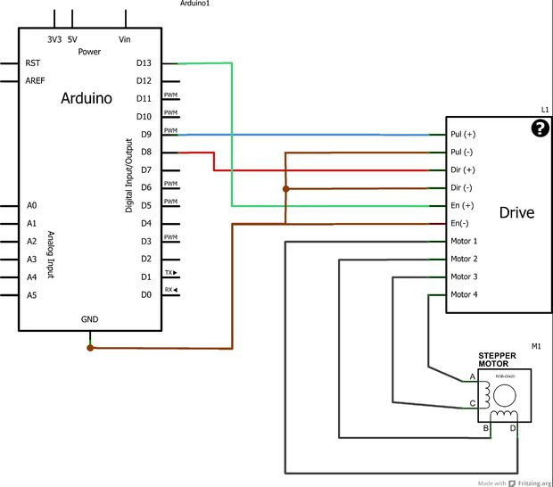
Robokits @ instructables.com have an article describing stepper motors and how to drive them using Arduino. They write:
Lots of People want to build Them own small Cnc machine . they started with drives stepper motor but they stacked in controller Programming . In this instructable Robokits will provide a resource to control your Stepper motor with Arduino. Before Programming we have to learn some basics Related to Stepper motor .
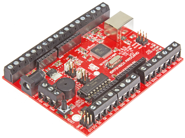
Have you read the BrainBox Arduino article in the latest edition of Elektor magazine? BrainBox Arduino is a rugged version of the Arduino Leonardo. Thanks to its sturdy screw terminals, a number of different power supply options, an on-board buzzer and a motor-driver IC that connects directly to motors, there is usually no need for breadboards, extra ICs or shields in most applications.
BrainBox Arduino: A ‘tough’ Arduino with screw terminals – [Link]
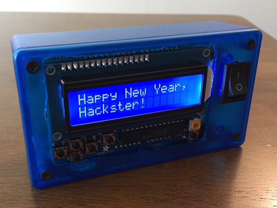
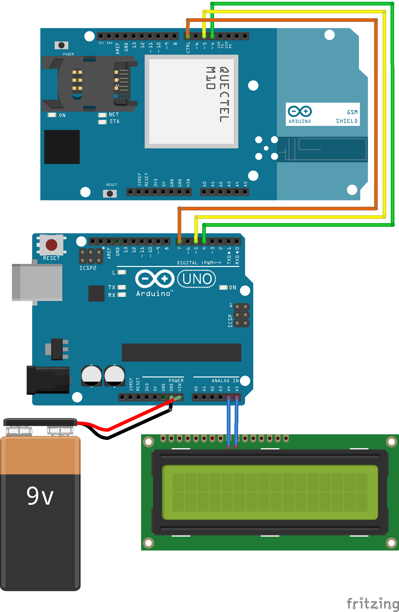
This Arduino-based pager by Mike Schaus will allow you to send and receive real SMS text messages. This messaging device has its own SIM card and phone number.
In order to build this project you need the following parts:
And you will need to use this software to run the project: Hologram Data Router.
This project was made possible as part of Hologram’s Hacker-In-Residence program, The Hologram Global SIM Card allows you to connect you IoT device everywhere. Paired with a powerful device management platform and API. It provides a cellular data service that works with any device that accepts a SIM card. In addition it is totally inexpensive.
GSM shield, the Hologram things, and Arduino stacked on top of each other made a good combination to build such a project. For powering the project, Mike had used a 9V battery as an option, and still, powering from USB is possible.
Mike had designed this project so it could be used by children instead of a real cell phone, or it could be used as an “SOS” button for someone working alone outdoors or even exercising.
Check this video to know how this project works:
The amazing thing about Adafruit LCD shield that it only uses 2 pins of Arduino since it works over the I2C bus, which results with many places left for future features.
This is the schematics of the project: It is super easy, the wires mean putting the pieces on top of each other.
And here is the Arduino code used:
#include <GSM.h>#define PINNUMBER ""// include the LCD library code:#include <Wire.h>#include <Adafruit_RGBLCDShield.h>#include <utility/Adafruit_MCP23017.h>// The shield uses the I2C SCL and SDA pins. On classic Arduinos// this is Analog 4 and 5 so you can't use those for analogRead() anymore// However, you can connect other I2C sensors to the I2C bus and share// the I2C bus.
Adafruit_RGBLCDShield lcd = Adafruit_RGBLCDShield();
// These #defines make it easy to set the backlight color#define OFF 0x0#define ON 0x1// make the arrow special character on the LCDconst byte arrow[8] =
{
B00000, B00000, B01000, B01100, B01110, B01100, B01000, B00000
};
// initialize the GSM library instance
GSM gsmAccess(false); // include a 'true' parameter for debug enabled
GSM_SMS sms;
// char array of the telephone number to send SMS// change the number 12125551212 to a number// you have access tochar remoteNumber[20]="12125551212";
// Array to hold the number a SMS is retreived fromchar senderNumber[20];
// char array of the possible outgoing messages to choose from the menuchar* responses[]={"Mike=Awesome!", "Yes", "No", "Howdy!"};
//#define NUMRESPONSES 4 // if someone knows how to calculate this instead, I'm all ears#define NUMRESPONSES (sizeof(responses)/sizeof(char *)) // thanks to Steve Kemp's comment!int position=-1; // this way the first button press will always show first option of the menuint inByte =0; // incoming serial byte for keyboard interface
boolean backlight =true; // track backlight status for togglingunsignedlong previousMillis =0; // will store last time messages were checked#define CHECKINTERVAL 1500 // how often to check for text messagesvoidsetup() {
// put your setup code here, to run once:// initialize serial communications
Serial.begin(9600);
Serial.println(F("SMS Message Sender -- starting up..."));
// set up the LCD's number of columns and rows:
lcd.begin(16, 2);
// Print a message to the LCD
lcd.print(F("Hello, Hologram!"));
lcd.setCursor(0, 1);
lcd.print(F("Starting up..."));
lcd.setBacklight(ON);
// set up the arrow character for display
lcd.createChar(0, arrow);
// connection state
boolean notConnected =true;
// Start GSM shield// If your SIM has PIN, pass it as a parameter of begin() in quoteswhile(notConnected)
{
if(gsmAccess.begin(PINNUMBER)==GSM_READY) {
notConnected =false;
Serial.println(F("GSM is connected because you are so awesome"));
Serial.println(F("Waiting for messages, or send with \"s\""));
Serial.println();
lcd.clear();
lcd.setCursor(0,0);
homeScreen();
}
else
{
Serial.println(F("Not connected"));
lcd.clear();
lcd.setCursor(0,0);
lcd.print(F("Not connected"));
delay(1000);
}
}
}
// this is the menu system functionvoidshowResponses() {
// Serial.println(position); // only for debugging menu system
lcd.clear();
lcd.setCursor(0,0);
// make sure cursor position is legalif (position<0) position=0;
if (position>NUMRESPONSES-1) position = NUMRESPONSES-1;
// write current selection and next option if there is another option
lcd.write(0); //arrow character
lcd.print(position+1);
lcd.print("-");
lcd.print(responses[position]);
if (position < NUMRESPONSES-1) {
lcd.setCursor(0,1);
lcd.print(" ");
lcd.print(position+2);
lcd.print("-");
lcd.print(responses[position+1]);
}
}
voidhomeScreen() {
lcd.clear();
lcd.setCursor(0,0);
lcd.print("SMS Messenger!");
lcd.setCursor(0,1);
lcd.print("Ready; up/dn snd");
position=-1; //reset response selection
}
voidreceiveSMS(){
char c;
// If there are any SMSs available()if (sms.available()) {
Serial.println("Message received from:");
// Get remote number
sms.remoteNumber(senderNumber, 20);
Serial.println(senderNumber);
lcd.clear();
lcd.setCursor(0,0);
backlight =true;
lcd.setBacklight(ON);
// An example of message disposal// Any messages starting with # should be discardedif (sms.peek() =='#') {
Serial.println("Discarded SMS");
sms.flush();
}
// Read message bytes and print them// because sms.read only returns one character at a timeint i=0;
while (c = sms.read()) {
i++;
Serial.print(c);
if (i==17) lcd.setCursor(0, 1); // move to next line if neededif (i<33) lcd.print(c); // don't try to print more than 32 chars just in case
}
Serial.println("\nEND OF MESSAGE");
// Delete message from modem memory
sms.flush();
Serial.println("MESSAGE DELETED");
Serial.println();
// wait for right button to acknowlege before letting program continue
boolean acknowledged =false;
while(!acknowledged) {
uint8_t buttons = lcd.readButtons();
if (buttons & BUTTON_RIGHT) acknowledged =true;
delay(50); //short delay for troubleshooting -- without this it behaves strangely
}
homeScreen();
delay(400); // prevent multiple presses in a row
}
}
// function to show message options in the serial monitorvoidprintResponseOptions(){
for(int i=0; i<NUMRESPONSES; i++){
Serial.print(i);
Serial.print("-");
Serial.println(responses[i]);
}
Serial.println();
}
voidsendSMS(constchar* txtMsg){
Serial.print("Message to mobile number: ");
Serial.println(remoteNumber);
// print sms text info
Serial.println("SENDING");
Serial.println("Message:");
Serial.println(txtMsg);
// send the message
sms.beginSMS(remoteNumber);
sms.print(txtMsg);
// next, add a signature to the chosen message
sms.print(" --Be sure to connect with me on my blog http://mschausprojects.blogspot.com");
// call endSMS function to finish sending; it will return 1 if successfulif (sms.endSMS()==1) {
Serial.println("\nCOMPLETE!\n");
homeScreen();
}
else {
Serial.println("\nERROR\n");
lcd.clear();
lcd.setCursor(0,0);
lcd.print("error");
}
Serial.println();
}
voidloop() {
// put your main code here, to run repeatedly:uint8_t buttons = lcd.readButtons();
if (buttons) {
if (buttons & BUTTON_UP) {
position--;
showResponses();
backlight =true;
lcd.setBacklight(ON);
}
if (buttons & BUTTON_DOWN) {
position++;
showResponses();
backlight =true;
lcd.setBacklight(ON);
}
if (buttons & BUTTON_LEFT) {
homeScreen();
backlight =true;
lcd.setBacklight(ON);
}
if (buttons & BUTTON_RIGHT) {
backlight =!backlight; // toggle the backlight stateif (backlight) lcd.setBacklight(ON);
else lcd.setBacklight(OFF);
homeScreen(); // have to write to screen after turning light off, otherwise it goes blank
}
if (buttons & BUTTON_SELECT) {
// make sure cursor selected position is legalif (position<0) position=0;
lcd.clear();
lcd.setCursor(0,0);
lcd.print("Sending...");
lcd.setCursor(0,1);
lcd.print(responses[position]);
backlight =true;
lcd.setBacklight(ON);
sendSMS(responses[position]);
}
delay(200); // prevent multiple presses in a row
}
// this is for serial interface only, not related to LCD and buttons// send a message when I type "s" in serial monitor// then wait for my selection of the response numberif (Serial.available() >0) {
inByte = Serial.read(); // get incoming byteif (inByte =='s') {
printResponseOptions();
while (Serial.available() >0) { // clear the keyboard buffer just in casechar junk = Serial.read();
}
while (Serial.available() ==0) ; // Wait here until input buffer has a character
inByte = Serial.parseInt();
// would want to check for valid choice here to be more robust
sendSMS(responses[inByte]);
}
}
// check for new messages only once every few seconds to keep interface more responsiveunsignedlong currentMillis = millis();
if (currentMillis - previousMillis >= CHECKINTERVAL) {
previousMillis = currentMillis;
receiveSMS(); // takes about 26ms when there are no messages
}
}
CREDITS
R3tkcxkom1pu38aqb0bh
More details about this project are available on hackster.io and Mike’s own blog post. You can learn more about his projects on the same blog.
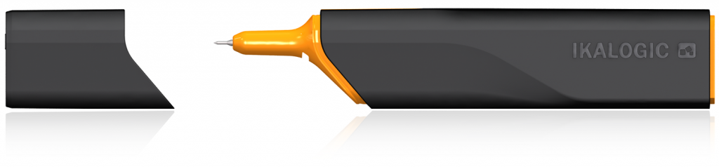
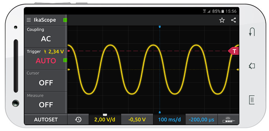
ikalogic.com launched “IkaScope” a new wireless oscilloscope probe that is able to make measurements directly on your mobile phone or your laptop. IkaScope transfers measured signals over high speed wifi connection and it will remember your home or office access points. It will work with iOS, Android and Windows devices (OSx will also be supported).
Specifications
Input range 10 mV/div. → 10 V/divMaximum input voltage 80 Vpp
Bandwidth 25 MHz
Timebase 100 ns/div → 10 s/div
Input impedance 1MΩ
Input Coupling AC, DC, GND
Trigger Rising or falling slopes
Digital specifications
Sampling rate 200 MSPS
Resolution 8-bits
Buffer 4K pts (4 * 1K Pts)1
IkaScope is a wireless oscilloscope probe, all contained in an ergonomic stylus. It uses a wifi connection to transfer signals to be displayed on any connected screen (Laptop, Smart-phone, Tablet or Desktop Computer). It’s equipped with a battery that can be recharged via any USB port. Being battery operated, IkaScope always provides 4000V+ galvanic isolation from power mains (even when being recharged).
IkaScope – a new wireless oscilloscope probe – [Link]
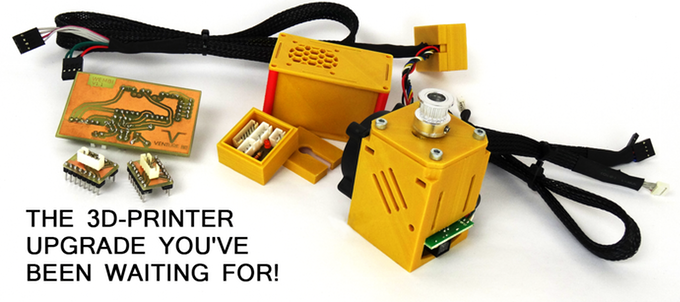
TeamVenture-Bit tipped us with their kickstarter campaign. It’s about a closed loop motor upgrade kit that will enable your 3D printer to print faster, silently and more consistently. Check it out.
Boasting an advanced PID compensation system that detects issues while your 3D printer or other CNC based machine is moving,
Wembi readjusts itself to eliminate printing problems and help you get the perfect prints fast!
Wembi – Closed Loop Motorupgrade for 3D Printer – [Link]
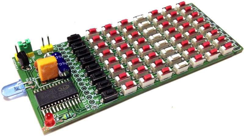
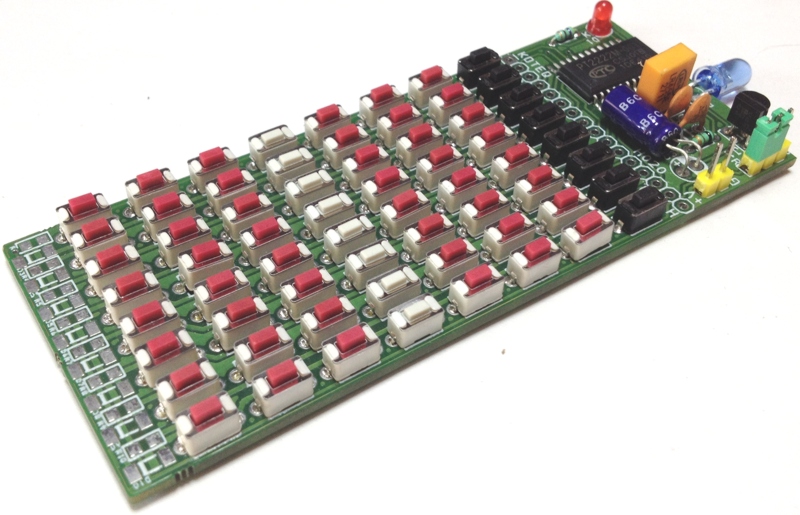
64 channels Infra-Red Remote Transmitter circuit build around PT2222M IC, The IC is pin to pin compatible with NEC uPD6122 respectively, the remote is capable of controlling 64 functions keys and 3 double keys. The PT2222M Infra-red remote control transmission ICs using the NEC transmission format that is ideally suited for TVs, DVD Players, Audio Equipment, Air Condition, etc. By combining external diode and resistors, maximum of 65536 custom codes can be specified. The NEC transmission format consists of leader codes, custom codes (16 Bits), and data codes (16 Bits). It can be used for various systems through decoding by a microcontroller.
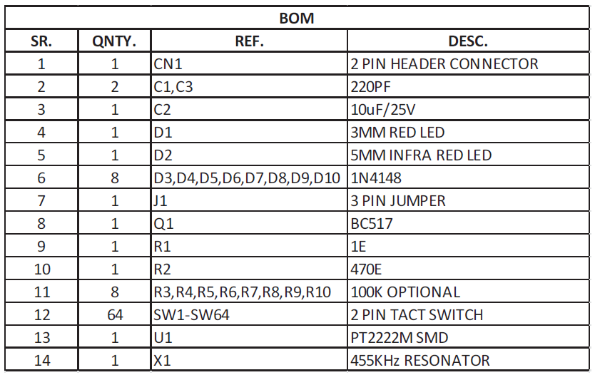
Features
Low Voltage 2V To 3.3V
Low Current dissipation: 1uA Max (Standby)
Custom Codes: 65536 (Set by optional provided diodes and resistors)
64 Codes (Single Input) , 3 Codes ( Double Input) , Expandable up to 128 Codes through J1 Jumper
64 Key Infrared Remote Controller using PT2222M – NEC Code – [Link]
64 channels Infra-Red Remote Transmitter circuit build around PT2222M IC, The IC is pin to pin compatible with NEC uPD6122 respectively, the remote is capable of controlling 64 functions keys and 3 double keys. The PT2222M Infra-red remote control transmission ICs using the NEC transmission format that is ideally suited for TVs, DVD Players, Audio Equipment, Air Condition, etc. By combining external diode and resistors, maximum of 65536 custom codes can be specified. The NEC transmission format consists of leader codes, custom codes (16 Bits), and data codes (16 Bits). It can be used for various systems through decoding by a microcontroller.
Features
Low Voltage 2V To 3.3V
Low Current dissipation: 1uA Max (Standby)
Custom Codes: 65536 (Set by optional provided diodes and resistors)
64 Codes (Single Input) , 3 Codes ( Double Input) , Expandable up to 128 Codes through J1 Jumper
Application
Audio Equipment
TV
Cable TV
Air Condition
DVD Player
Robotics
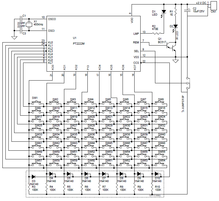
Key input pins (KI0 to KI7), key input/output pins (KI/O0 to KI/O7)
When several keys are pressed simultaneously, the transmission of the corresponding signals is inhibited by a multiple-input prevention circuit. In the case of double-key input, transmission is inhibited if both keys are pressed simultaneously (within 36 ms interval); if not pressed simultaneously, the priority of transmission is first key, then second key. When a key is pressed, the custom code and data code reading is initiated, and 36 ms later, output to REM output is initiated. Thus if the key is pressed during the initial 36 ms, one transmission is performed. If a key is kept pressed for 108 ms or longer, only leader codes are consecutively transmitted until the key is released. Keys can be operated intermittently at intervals as short as 126 ms (interval between two on’s), making this an extremely fast-response system.
The REM output pin outputs the transmission code, which consists of the leader code, custom code (16 bits), and data code (16 bits)
By controlling D7 of the data code with this pin, the PT2222M can transmit 64 and 128 different data codes, respectively. By connecting the SEL pin to VDD or VSS via on board Jumper , D7 is set to “0” or “1”, respectively.
By placing a diode between the CCS pin and the KI/O pin, it is possible to set a custom code. When a diode is connected, the corresponding custom code is “1”, and when not connected, it is “0”.
The LMP pin outputs a low-level signal while the REM pin outputs a transmission code.
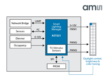
ams AG, a multinational semiconductor manufacturer and provider of high performance sensors and analog ICs, had announced the AS7221, an integrated white-tunable smart lighting manager that can be controlled through its network connection by means of simple text-based commands.
AS7221 Block Diagram
AS7221 is a networking-enabled IoT Smart Lighting Manager with embedded tri-stimulus color sensing for direct CIE color point mapping and control. IoT luminaire control is through a network connection, or by direct connection to 0-10V dimmers, with control outputs that include direct PWM to LED drivers and analog 0-10V to dimming ballasts. A simple text-based Smart Lighting Command Set and serial UART interface, enable easy integration to standard network clients.
Key features of AS7221:
Calibrated XYZ tri-stimulus color sensing for direct translation to CIE 1931/1976 standard observer color maps
Autonomous color point and lumen output adjustment resulting in automatic spectral and lumen maintenance
Simple UART interface for connection to network hardware clients for protocols such as Bluetooth, ZigBee and WiFi
Smart Lighting Command Set (SLCS) uses simple text-based commands to control and configure a wide variety of functions
Directly interfaces to 0-10V dimmer controls and standard occupancy sensors
Built-in PWM generator to dim LED lamps and luminaires
12-bit resolution for precise dimming down to 1%
0-10V analog output for control of conventional dimming ballasts in a current steering design
20-pin LGA package 4.5mm x 4.7mm x 2.5mm with integrated aperture
“The next generation of lighting will be defined by three key characteristics: controllability, adaptation and connected architectures,” said Tom Griffiths, Senior Marketing Manager at ams. “Our new family of smart lighting managers meet those criteria. With this latest entry, we are addressing the luminaire manufacturers’ critical time-to-market challenge for developing and deploying a spectrally tunable luminaire that is cost-effective, accurate, and which smoothly integrates into the Internet of Things”.
The AS7221 is the first extension to ams’s recently announced Cognitive Lighting™ smart lighting manager family. The compact AS7221 will be available in a 5x5mm LGA package, for flexible integration into both luminaires and larger replacement lamps.
There are main domains of AS7221 applications, some of them are:
Smart home and smart building
Variable CCT general lighting industrial lighting
Retail and hospitality lighting with white-color tuning
LED tro ers, panel and downlights
LED replacement lamps (LED bulbs)
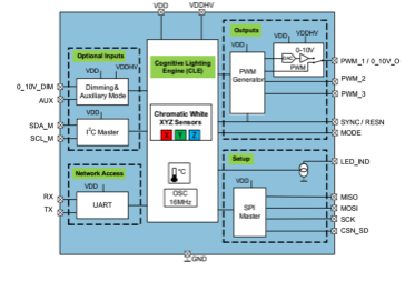
AS7221 Functional Diagram
Pricing for the AS7221 Spectral Tuning IoT Smart Lighting Manager is set at $3.13 in quantities of 10,000 pieces, and is available in production volumes now.