JeVois, The Open-Source Smart Vision Camera

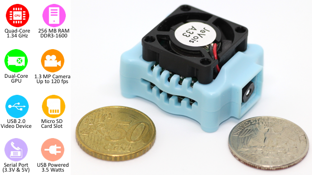
JeVois, which can be translated from French as: I see, is an open-source quad-core camera that can be connected easily with your project whether you are using Arduino, Raspberry Pi or just running it on your PC. JeVois contains a video sensor, quad-core CPU, USB video and a serial port in only 1.7 cubic inches. To start working with your JeVois you only need to insert a microSD card loaded with the provided open-source machine vision algorithms and then connecting it to your computer. It will work immediately just by opening a camera software.

The process is as follows: video captured by the camera sensor, processed on JeVois processor, and results are sent over USB to the host computer or to the micro controller.

On your computer, you can use any camera software to see the results, also you can check different vision algorithms by selecting different resolutions and frame rates.

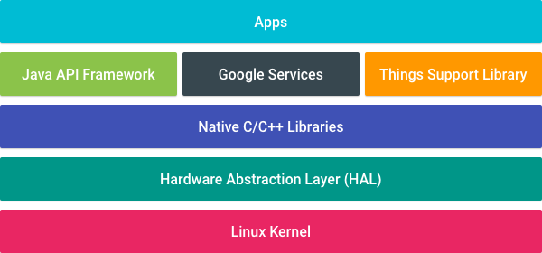
It has the following software and hardware frameworks:

“For ease of programming and configuration, all of the operating system, core JeVois software, and any necessary data files are stored on a single high-speed Micro-SD card that can easily be removed and plugged into a desktop or laptop computer.  The JeVois software framework combines custom Linux kernel drivers for camera sensor and for USB output, written in C, and a custom high-level vision processing framework, written in C++-17. “

Easy to integrate  with other open-source libraries, including tiny-dnn, OpenCV, boost, zBar, Eigen, turbojpeg, etc.  This framework is scalable since the operating system infrastructure is built using the buildroot framework where adding and using different libraries is easy. New vision modules can be added to the core of JeVois thanks to the fact the core software is managed by cmake. Thus, you can customize the vision algorithm you would like to run your JeVois.

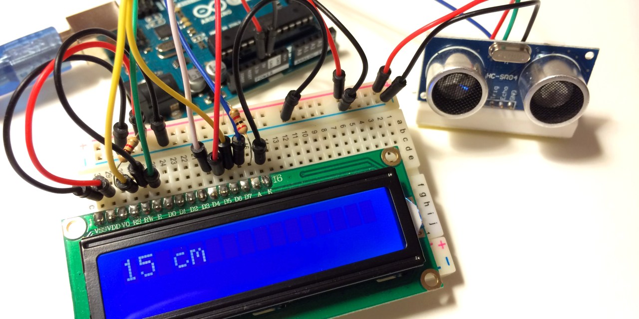
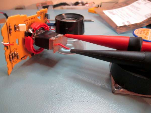
In addition, it is easy to use, for example only 4 Wires are needed to connect it with Arduino: 5 or 3.3 V, GND, Tx and Rx!

JeVois is now live in a Kickstarter Campaign, check this video for better understanding:

For more information about the specifications and technical details, check the campaign page. You can pre-order your JeVois now for $45, there are still 20 days to go.

JeVois started as an educational project, to encourage the study of machine vision, computational neuroscience, and machine learning as part of introductory programming and robotics courses at all levels (from K-12 to Ph.D.). It is funded by Science Foundation (NSF) and the Defense Advanced Research Projects Agency (DARPA).

If you are interested in developing the core of JeVois check the documentation provided here.

Constant Current Laser Diode Driver Circuit Using OPA2350 OpAmp

The voltage-controlled current source circuit can be used to drive a constant current into a signal or pump laser diode. This simple linear driver provides a cleaner drive current into a laser diode than switching PWM drivers. The basic circuit is that of a Howland current pump with a current booster (Q1) on the output of a R-R CMOS OPA2350 op amp (U1). Laser diode current is sensed by differentially measuring the voltage drop across a shunt resistor (RSHUNT) in series with the laser diode. The output current is controlled by the input voltage (VIN) that comes from Trim pot PR1.

Features

  • Supply 3,3V DC
  • Load Up to 300mA
  • PR1 Trimpot Current Adjust

Constant Current Laser Diode Driver Circuit Using OPA2350 OpAmp – [Link]

Constant Current Laser Diode Driver Circuit Using OPA2350 OpAmp

The voltage-controlled current source circuit can be used to drive a constant current into a signal or pump laser diode. This simple linear driver provides a cleaner drive current into a laser diode than switching PWM drivers. The basic circuit is that of a Howland current pump with a current booster (Q1) on the output of a R-R CMOS OPA2350 op amp (U1). Laser diode current is sensed by differentially measuring the voltage drop across a shunt resistor (RSHUNT) in series with the laser diode. The output current is controlled by the input voltage (VIN) that comes from Trim pot PR1.

Features

  • Supply 3,3V DC
  • Load Up to 300mA
  • PR1 Trimpot Current Adjust

Schematic

Parts List

Photos

Video

OPA2350 Datasheet

How to Set Up an Ultrasonic Range Finder on an Arduino

circuitbasics.com has a new tutorial on how to measure distance using Arduino and an ultrasonic sensor.

Ultrasonic range finders are fun little modules that measure distance. You can use them to find the precise distance to an object, or also just to detect when something is within range of the sensor (like a motion detector). Ultrasonic range finders are ideal for projects involving robotic navigation, object avoidance, and home security. Because they use sound to measure distance, they work just as well in the dark as they do in the light. The ultrasonic range finder we will be using in this tutorial is the HC-SR04. The HC-SR04 can measure distances from 2 cm to 4oo cm with an accuracy of ±3 mm.

How to Set Up an Ultrasonic Range Finder on an Arduino – [Link]

DIY IKEA Wireless Qi Charging

mcuoneclipse.com writes:

To my surprise, when I visited a nearby IKEA store yesterday, the older iPhone and Samsung Galaxy S4 (VITAHULT) Qi receivers were on sale for CHF 0.95 (about US$1): what could be wrong with buying a few of them? At this point, I should probably mention the ‘rolling eyes’ of my wife😉.

The question is: can I use these for my projects? So I decided to open up the wireless phone cover. The cover has to plastic parts, and with a bit tweaking I was able to separate them. Insider there is the battery connector, the receiver circuit and the charging coil under a black FFDM (Flux Field Directional Material):

DIY IKEA Wireless Qi Charging – [Link]

NVSW319A, A New High Power LED By Nichia

Nichia Corporation, the Japanese chemical engineering and manufacturing company, announced the NVSW319A as a new high-power LED that achieves 164 lm/W at 700mA (5,000K).

The 319A is a 3.5×3.5×2.1 mm size LED which is footprint compatible with the old 3.5mm LEDs. The breakdown is specified at 1,050 mA (~3 W). Nichia planned to start the mass production of this LEDs in the end of December 2016 or in the early January 2017.

“The 319A is a production device, i.e. not one shining brightly deep down in a liquid nitrogen vessel or in the minds of a few theorists at MIT.” Nichia say.

A variant with 3000K color temperature is expected to yield 415 lm with a minimum CRI (color rendering index) of 80. This device won’t give you much deep red though as its R9 CRI specification is zero.

Source: elektor

Android Things, Google’s IoT Platform

Google had launched Android Things,  a new comprehensive IoT platform for building smart devices on top of Android APIs and Google’s own services. Android Things is now available as a developer preview.

Android Things was basically launched as an enhancement for Brillo, Android based OS used for embedded development in particular for low-power IoT devices, and it is based on its feedback and best practices. Google had announced Android Things as re-branding of Brillo to solve many issues like the security of IoT devices.

Platform Architecture

Both work in conjunction with Weave, an open, standardized communications protocol that supports various discovery, provisioning, and authentication functions. Weave enables device setup, phone-to-device-to-cloud communication, and user interaction from mobile devices and the web. The chief benefit is allowing a “standardized” way for consumers to set up devices. Belkin WeMo, LiFX, Honeywell, Wink, TP-Link and First Alert will adopt Weave to make their devices able to interact with some Google products like Google Assistant.

One of the great things about Brillo was the security issue with IoT applications solved by choosing to use secure boot and signed over-the-air updates and providing timely patches at the OS level. Partnered with hardware manufacturers to build new devices based on Intel Edison, NXP Pico and the Raspberry Pi 3, Google will build the needed infrastructure to run the OS updates and fix security issues respectively on these devices.

Android Things makes developing connected embedded devices easy by providing the same Android development tools, best-in-class Android framework, and Google APIs that make developers successful on mobile. For more details about Android Things you can check the documentation provided here, where you can find also the developer’s preview.

Circuit Board Design for Beginners

By: Alex Danovich,President San Francisco Circuits

We live in an exciting time where we see a resurgence in electronics as a hobby. Mass production has wiped out a generation or two of kids learning to build radios from scratch with their mom or dad. In the good old days, not sure when, you had companies like Heathkit walk you through building a full size color TV at home, for example. “Yes, I made that!” you’d proudly exclaim to yourself after hours of work.

What’s causing this hobbyist resurgence?

  • Television shows such as How it’s Made, Mythbusters and other programming on TLC.
  • Websites such as instructables.com, hackaday.com, and specialized hobbyist blogs.
  • Interest in RC cars, robotics, gaming, computers etc.
  • Advent of Arduino boards, modules and free software.
  • Open source software/hardware.
  • The whole maker movement in general.

So what does this have to do with making circuit boards?

Well, it’s now easy and fairly cheap to make a nice circuit board for your project without a lot of fuss. So you want to get the kids away from the TV and build a fun, blinking LED project for your kids? Gone are the days of tedious hand wiring, empty coffee cups, smoking components and unprintable words; they’re now replaced with easy online applications.

In times past, I would sketch out a circuit on a raw copper board using a Sharpie pen. Then I dipped it in a bath of some nice toxic Ferric Chloride from Radio Shack and waited and waited. After a long while, you removed the board and then hand drilled the work of art. To prevent corrosion, you rubbed some silver powder on it. Finally, stuff the board and there it is. Your mom (or wife) is now furious over the stains, mess and the stink you just created. But there it is. You let out a great sigh of personal satisfaction.

Fast forward to post-dinosaur times.

The Steps to Glory

  1. There are several good choices for a free schematic and circuit board design program. I prefer Eagle. Lots of hobbyists and pros use it so there are lots of free designs and tutorials available. The free version is somewhat limited but very useful for smaller work. What’s nice is that if you like this as a hobby, you can progress to the “pro” version.
  2. Next you will have to find a “board house” to make the boards. The author of this article is a good place to start for a free quote – San Francisco Circuits.  SFCircuits is a full service PCB fabrication and PCB assembly provider  from hobbyist to military grade work with some helpful tutorials in the PCB School section. Who knows – you just might go from blinking LED project one day to a nice ICBM with them. Impress the neighbors?
  3. Once you have a board on its way, consider it time for buying PCB assembly parts from Digikey or Mouser. They are great distributors and cater to hobbyists with smaller quantities with good pricing. It’s so much better than Radio Shack which carries less and less useful components lately. However, you must be careful buying integrated circuits, resistors, capacitors, etc. online as they come in a dizzying array of sizes.

Design Considerations

  1. Sketch out on paper what your PCB will look like.  Do you need holes for mounting? Do you have a box in mind? You can get a nice plastic case with battery compartments from Pactec. Did you leave room for connectors to stick out? Make sure you leave clearance for taller components. Part of the trick is to visualize all the pieces and how they fit. Make sure you have clearance for your soldering iron as well.
  2. It’s best to do a single-sided circuit board. You have connection traces between the components on the top side only. A double-sided board can get complicated for first timers. For sensitive analog and high speed digital circuits, consider adding a ground place area on the backside.
  3. Once your layout is done, a critical step is to verify every trace. Adding jumper wires later is not fun. The traditional method is to print the schematic and start in one corner with your favorite highlighter color. Verify every line. A very important thing to remember is that some schematic packages hide the chips’ power lines for clarity. So you may have chips with no power.

An alternate method is to create a “netlist.” This is a point to point list of every connection (more highlighter). A really smart thing is to allow the layout software (if it supports it) to do an automated netlist check. It will give you a list of all the errors, a much faster solution. I like to do some of the manual method as a sanity check to make sure all is well. There is a lot to think about. Some places sell scrap boards to check your soldering skills or to make art out of other folks’ mistakes. Do your best to avoid it.

So cross your fingers, say your prayers and away you go.

Now aren’t hose blinking LEDs pretty cool?

“Yes, I made that”.

This article was written as a guest post by San Francisco Circuits, a PCB solutions provider located in Northern California.

Radioactivity detection using very simple ionization chamber

Robert Gawron tipped us with his latest build. He writes:

Today I will show a very simple ionization chamber that can detect radioactivity. I was able to detect with it ionizing radiation from a smoke detector (Am241 isotope). It’s also immune to electromagnetic interference (EMI) due to a good shielding.

Radioactivity detection using very simple ionization chamber – [Link]

TOP PCB Companies