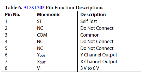
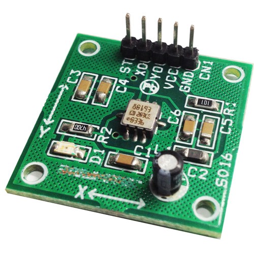
The ADXL203 Module is high precision, low power, complete dual-axis accelerometers with signal conditioned voltage outputs, all on a single, monolithic IC. The ADXL203 measure acceleration with a full-scale range of ±1.7 g, ±5 g, or ±18 g. The ADXL203 can measure both dynamic acceleration (for example, vibration) and static acceleration (for example, gravity).The typical noise floor is 110 μg/√Hz, allowing signals below 1 mg (0.06° of inclination) to be resolved in tilt sensing applications using narrow bandwidths (<60 Hz).The user selects the bandwidth of the accelerometer using Capacitor CX and Capacitor CY at the XOUT and YOUT pins. Bandwidths of 0.5 Hz to 2.5 kHz can be selected to suit the application.
+/- 1.7g Dual-Axis IMEMS Accelerometer Using ADXL203 – [Link]
The ADXL203 Module is high precision, low power, complete dual-axis accelerometers with signal conditioned voltage outputs, all on a single, monolithic IC. The ADXL203 measure acceleration with a full-scale range of ±1.7 g, ±5 g, or ±18 g. The ADXL203 can measure both dynamic acceleration (for example, vibration) and static acceleration (for example, gravity).The typical noise floor is 110 μg/√Hz, allowing signals below 1 mg (0.06° of inclination) to be resolved in tilt sensing applications using narrow bandwidths (<60 Hz).The user selects the bandwidth of the accelerometer using Capacitor CX and Capacitor CY at the XOUT and YOUT pins. Bandwidths of 0.5 Hz to 2.5 kHz can be selected to suit the application.
Features
Supply 4.75V To 5.25V
Output 1.4V To 3V ( 2.2V Center ) Aproxx.
High performance, dual-axis accelerometer on a single IC chip
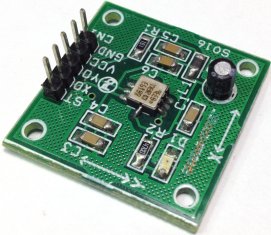
5 mm × 5 mm × 2 mm LCC package
1 mg resolution at 60 Hz
Low power: 700 μA at VS = 5 V (typical)
High zero g bias stability
High sensitivity accuracy
−40°C to +125°C temperature range
X and Y axes aligned to within 0.1° (typical)
Bandwidth adjustment with a single capacitor
Single-supply operation
3500 g shock survival
Sensitivity is essentially ratiometric to VCC For VCC = 4.75 V to 5.25 V, sensitivity is 186 mV/V/g to 215 mV/V/g.
4 Actual frequency response controlled by user-supplied external capacitor (CX, CY).
5 Bandwidth = 1/(2 × π × 32 kΩ × C). For CX, CY = 0.002 μF, bandwidth = 2500 Hz. For CX, CY = 10 μF, bandwidth = 0.5 Hz. Minimum/maximum values are not tested. 6 Self-test response changes cubically with VS.
7 Larger values of CX, CY increase turn-on time. Turn-on time is approximately 160 × CX or CY + 4 ms, where CX, CY are in μF.
Applications
Vehicle dynamic controls
Electronic chassis controls
Platform stabilization/leveling
Navigation
Alarms and motion detectors
High accuracy, 2-axis tilt sensing
Vibration monitoring and compensation
Theory of Operation
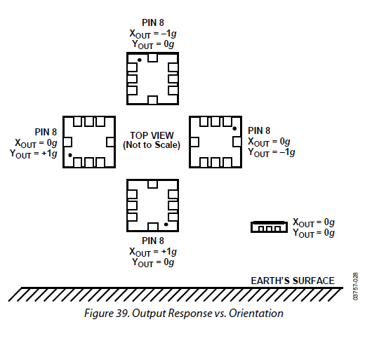
The ADXL203 are complete acceleration measurement systems on a single, monolithic IC. The is a single-axis accelerometer, and the ADXL203 is a dual-axis accelerometer. Both parts contain a polysilicon surface-micro-machined sensor and signal conditioning circuitry to implement an open-loop acceleration measurement architecture. The output signals are analog voltages that are proportional to acceleration. The ADXL203 are capable of measuring both positive and negative accelerations from ±1.7 g to at least ±18 g. The accelerometer can measure static acceleration forces, such as gravity, allowing it to be used as a tilt sensor. The sensor is a surface-micromachined polysilicon structure built on top of the silicon wafer. Polysilicon springs suspend the structure over the surface of the wafer and provide a resistance against acceleration forces. Deflection of the structure is measured using a differential capacitor that consists of independent fixed plates and plates attached to the moving mass. The fixed plates are driven by 180° out-of-phase square waves. Acceleration deflects the beam and unbalances the differential capacitor, resulting in an output square wave whose amplitude is proportional to acceleration. Phase-sensitive demodulation techniques are then used to rectify the signal and determine the direction of the acceleration.
The output of the demodulator is amplified and brought off-chip through a 32 kΩ resistor. At this point, the user can set the signal bandwidth of the device by adding a capacitor. This filtering improves measurement resolution and helps prevent aliasing. PERFORMANCE Rather than using additional temperature compensation circuitry, innovative design techniques have been used to ensure that high performance is built in. As a result, there is essentially no quantization error or nonmonotonic behavior, and temperature hysteresis is very low (typically less than 10 mg over the −40°C to +125°C temperature range). Figure 11 shows the 0 g output performance of eight parts (x and y axes) over a −40°C to +125°C temperature range. Figure 13 demonstrates the typical sensitivity shift over temperature for VS = 5 V. Sensitivity stability is optimized for VS = 5 V but is still very good over the specified range; it is typically better than ±1% over temperature at VS = 3 V.
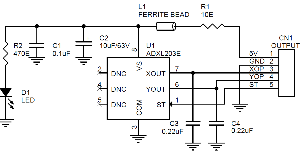
SETTING THE BANDWIDTH USING CX AND CY
The ADXL203 has provisions for band limiting the XOUT and YOUT pins. Capacitors must be added at these pins to implement low-pass filtering for antialiasing and noise reduction. The equation for the 3 dB bandwidth is
f–3 dB = 1/(2π(32 kΩ) × C(X, Y))
or more simply,
f–3 dB = 5 μF/C(X, Y)
The tolerance of the internal resistor (RFILT) can vary typically as much as ±25% of its nominal value (32 kΩ); thus, the bandwidth varies accordingly. A minimum capacitance of 2000 pF for CX and CY is required in all cases.
The open-source Arduino Software (IDE) makes it easy to write code and upload it to the board. It runs on Windows, Mac OS X, and Linux. The environment is written in Java and based on Processing and other open-source software.
Arduino has just launched its latest software version: IDE 1.8.0! What makes this software special is that it can be used with any Arduino board whether you get it from Arduino.cc or Arduino.org.
Thanks to updating the SAMD core, this IDE is ready to run the M0 and M0 PRO, Zero, MKR1000, and the newly-launched Primo and MKRZero.
If you are a Linux user, it is possible now to run the IDE directly using command line without the need of X11 display anymore.
Check the release note of this version:
ARDUINO 1.8.0 – 2016.12.20
[ide]
* Linux: running in command line mode doesn’t require an X11 display anymore
* “Save as” now clears the “modified” status
* builder: Paths with strange UTF8 chars are now correctly handled
* builder: .hpp and .hh file extensions are now considered valid sketch extension
* builder: core.a is not rebuild if not needed (improve build time in particular for big projects)
* Fixed swapped actions “Copy for Forum” and “Copy as HTML”
* Linux/osx: If an editor tab is a symbolic link it is no more replaced with a real file when saving (see #5478)
* Increased the upload timeout to 5 minutes (it was 2 min, but it may be not sufficient when uploading via UART a big sketch)
[core]
* Added Arduino.org boards
* Added Adafruit Circuit Playground board
* Added “-g” option to linker to keep debug information in the .elf file (see #5539)
* avrdude: Added fake configuration for EFUSE on atmega8 part. This solves a long standing issue with “Burn bootloader”.
Thanks @rigelinorion, @awatterott
The unified Arduino software can be downloaded here and more installation instructions are available at the Getting Started page.
This work has never been done without the efforts of the community. The entire revision log for a complete list of changes and credits is available here, and the full source code is on Github.
Ambiq Micro, the leader in ultra-low power solutions, launched the Apollo 2 Wearables and IoT Platform. The Platform offers breakthrough power consumption of under 10 μA/MHz, which allows for double the battery life in wearable devices. Apollo 2’s performance will lead to longer battery life, enhanced intelligence and improved functionality in wearables and IoT consumer electronics (CE) products. Ambiq Micro’s Apollo 2 Platform provides dramatic reductions in energy consumption through its patented Subthreshold Power Optimized Technology (SPOT™) technology.
“The incredible pace of Moore’s Law disrupted computing every year or two and took us from room-sized supercomputers to billions of pocket-sized mobile phones,” said Scott Hanson, founder and CTO, Ambiq Micro. “Ambiq Micro’s SPOT technology will bring a similar pace of innovation to the IoT. As the foundation of our Apollo MCU, SPOT allows us to drive energy consumption below what we previously imagined was possible. With Apollo 2, we extend the SPOT technology to achieve new efficiencies for the next wave of IoT and connected devices.”
Apollo 2 MCU key features and specifications
Ultra-low supply current
<10 μA/MHz executing from flash at 3.3 V
<10 μA/MHz executing from RAM at 3.3 V
ARM Cortex-M4 Processor up to 48 MHz with FPU, MMU, wake-up interrupt controller with 32 interrupts
Ultra-low power memory
Up to 1 MB of flash memory for code/data
Up to 256 KB of low leakage RAM for code/data
16kB 1 or 2-way Associative Cache
Ultra-low power interface for off-chip sensors
14 bit, 15-channel, up to 1.2 MS/s ADC
Voltage comparator
Temperature sensor with +/-2ºC accuracy
Serial peripherals – 6x I2C/SPI master,1x I2C/SPI slave,2x UART, PDM for mono and stereo audio microphone
Clock sources
32.768 kHz XTAL oscillator
Low frequency RC oscillator – 1.024 kHz
High frequency RC oscillator – 48 MHz
RTC based on Ambiq’s AM08X5/18X5 families
Wide operating range – 1.8-3.6 V, –40 to 85°C
Package – 2.5 x 2.5 mm 49-pin CSP with 34 GPIO; 4.5 x 4.5 mm 64-pin BGA with 50 GPIO
You can check the product page to know more about Apollo2, but for further information and documentation you have to contact Ambiq Micro.
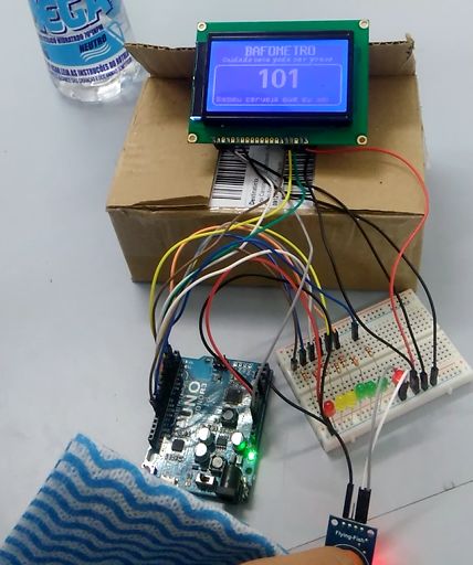
Today I am going to discuss how to make a very simple DIY Breathalyzer using Arduino UNO and few external components. Ana Carolina designed this project as an instructable in instructables.com. This is a low-cost project and a useful one too. If you have no idea about what breathalyzer is, let me explain briefly: A breathalyzer is a device for estimating blood alcohol content (BAC) from a breath sample. Check the link given for more information.
Arduino Based Breathalyzer
Requirements:
Arduino Uno
MQ-3 Alcohol Sensor
128×64 LCD (Liquid Crystal Display)
7 × 330 Ohm Resistor
7 × LEDs (1 Red, 2 Yellow, 3 Green and one other color)
Jumpers Wires
Breadboard
Soldering Iron (optional)
Solder Wire (optional)
Details:
This project is very simple. Here we are using an array of six LEDs and a 128×64 LCD to display the alcohol level. The presence of alcohol is sensed by an MQ-3 alcohol sensor and then analyzed by an Arduino board. We are using Arduino UNO in this project, but any model can do the job.
Three Green LEDs represent that alcohol level is OK and within the safe limit. Two Yellow LEDs are used to describe that safe limit is going to be reached, and you know it well why the Red LED is there. In fact, those LEDs are used just to give you a quick idea. If you want to know the exact value, the display is there for you.
You can tweak the program and re-calibrate the breathalyzer. But you must remember that breathalyzer doesn’t precisely measure your blood alcohol content, rather it estimates a value from the amount of alcohol in your breath.
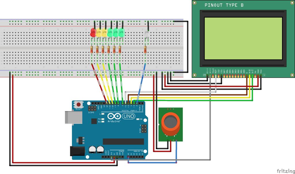
Circuit:
Breathalyzer Circuit On Breadboard
You can make the circuit also on PCB or Veroboard. But for the prototyping purpose, the breadboard is the best choice. You can see how straight forward the connections are.
The Code:
Some part of the original code was in Portuguese. So I have translated it into English. Also, the original code shared by the author in instrucatbles.com is a buggy one. So, I recommend you to use my bug-free code instead of the original one.
Please note that you have to download and add the u8glib library in Arduino IDE beforehand. It is very important. You can either download the u8glib v1.14 library for Arduino directly or go to the site and choose what to download.
Follow the given steps to add a .zip library in your sketch: Open IDE and click on Sketch → Include Library → Add .zip Library. Now select the downloaded .zip library file. You needn’t unzip it.
When everything is done, verify and upload the code to Arduino.
Test It:
I must not recommend you to drink alcohol just for testing the breathalyzer. Rather get a towel and spray alcohol on it. Now hold the towel in front of the sensor. Move it back and forth to observe the change in reading. It may take a while for the breathalyzer to stabilize.
Consider watching the video for a better understanding:
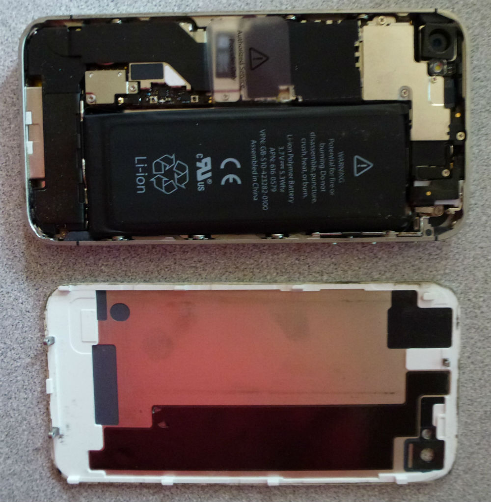
Brian Dipert discuss his experience replacing an iphone battery @ edn.com:
About a week ago, in preparing to run some errands, I plugged my iPhone 4S into the charger in my car so that I could stream Pandora while I drove. Oddly, a “this accessory may not be supported” message appeared on-screen; when I unplugged and re-plugged the iPhone to the charger, it didn’t reappear, so I didn’t think anything more of it … until a half hour later, when the iPhone again alerted me, this time with a “low battery” message.
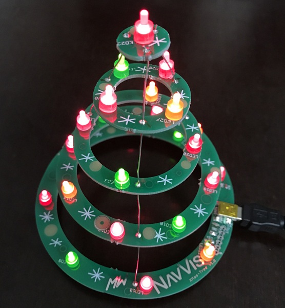
Matthias created a X-Mas tree project using the DirtyPCB boards from dangerousprotorypes.com :
The project features an USB capable PIC16F1549 µC with:
USB FS device
48 MHz internal Oscillator
2 PWM modules
10-bit ADC with Voltage Reference
Integrated Temperature Indicator Module
The LEDs are connected to the 2 PWM outputs via N-mos drivers. A Potentiometer is connected to one ADC channel for controlling the brightness of the LEDs or possibly the speed or variation of animations. Different modes of the X-mass tree can be switched by pressing a push button.
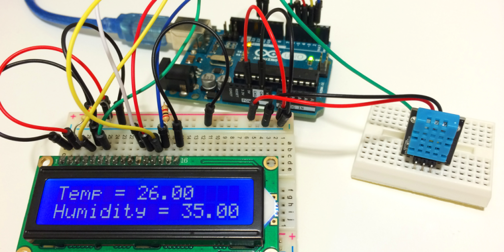
circuitbasics.com has a new tutorial on how to interface DHT11 humidity sensor to Arduino board. Sample code is provided
Because of their low cost and small size, DHT11 humidity and temperature sensors are perfect for lots of different DIY electronics projects. Some projects where the DHT11 would be useful include remote weather stations, home environment control systems, and agricultural/garden monitoring systems.
How to Set Up the DHT11 Humidity Sensor on an Arduino – [Link]
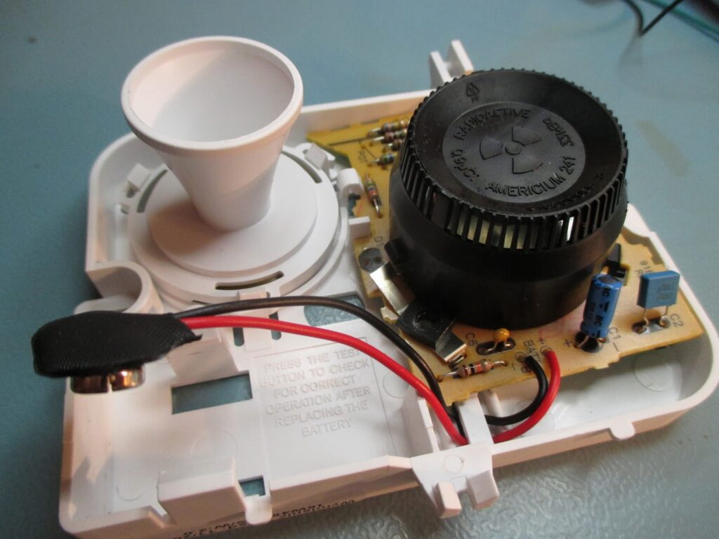
Not many people know, but in some smoke detectors, radioactive materials play an essential role. Today I will present one of those devices, and my -successful- attempt to reverse engineer it and get the circuit diagram.
Nuclear physics applied in smoke detectors – [Link]
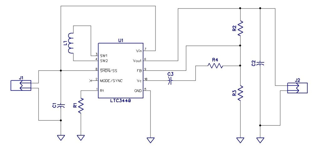
This project shows a DC-DC buck boost circuit which can produce an output of 3.3V for an input of 2.7V to 4.2V , for example from a Li-on battery. The Circuit uses LTC3440 Buck boost IC which is a fixed frequency boost converter. To get high efficient results, inductor with high frequency core material should be used.
Features
Input(V): 2.7V DC to 4.2V DC
Output(V): 3.3V DC
Output load: 600mA
PCB:23mmX15mm
2.7V-4.2V input to 3.3V output Buck-Boost Converter – [Link]