The Winkel Board, All-in-one Arduino Compatible Board

Mintbox Technologies is an Indian tech startup who build smarter connected devices for everyone. It is specialized in consumer electronics, open source software & hardware, PCB design services. Mintbox latest product is The Winkel Board, a powerful new Arduino-compatible, open source hardware platform for development and prototyping.

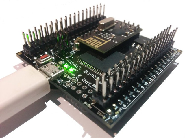
Based on the Atmel ATmega128 microcontroller, The Winkel Board is designed to be easy to use for both junior and senior makers including many popular peripherals such as WiFi, radio, and Bluetooth on board.

Check this video to know The Winkel Board features:

By providing an all-in-one compatible Arduino board, Mintbox team is working to solve the routine each maker does before starting a project, which they clarify in this list:

TODO for a maker while building something awesome:

  • Prepare a list of right electronics components
  • Prepare BOM
  • Search them locally or online to fit the BOM
  • Wait for the components to arrive if sourced online
  • Getting started with prototyping
  • Go online again studying libraries and figuring out how they can be interfaced on breadboard or etch a PCB
  • Finally start building and actually working on your project and then try not to rage quit

The Winkel Board specifications

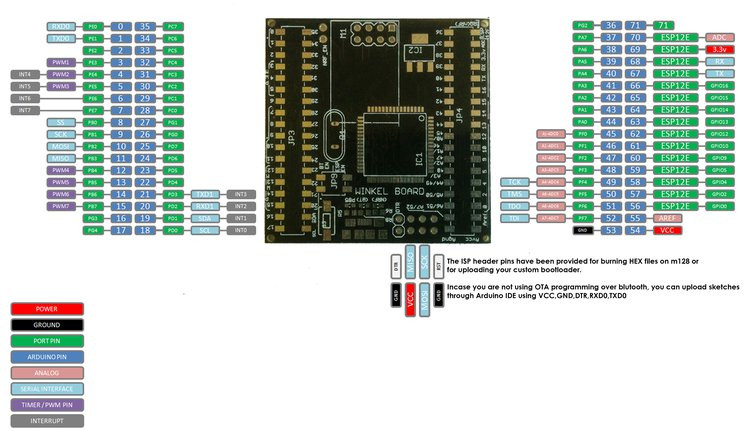
  • MCU – Microchip/Atmel ATmega128 MCU @ 16 MHz with 128KB flash memory, 4KB SRAM, 4KB EEPROM
  • Connectivity
    • WiFi 802.11 b/g/n via ESP12E module based on ESP8266
    • Bluetooth 2.0 + EDR via HC-05 module
    • RF Radio – NRF24l01 2.4 GHz ISM radio.
  • I/Os (through both Atmel MCU and ESP8266)
    • 38x Digital I/Os
    • 7x PWM Digital I/Os
    • 8x Analog Inputs
  • USB – micro USB port for programming and power
  • Misc – DS3231 Real-Time Clock + CR2032 battery slot, a few LEDS, reset button, jumper for OTA mode, ISP header, optional MPU-6050 Gyro+accelerometer mount
  • Power Supply – 5 V
  • Dimensions – TBD
Pinout Diagram

This board is said to be a one stop platform, that combines different communication protocols and allows a lot of I/O operations, thus you can do everything at once or choose specific on-board components to work with.

The Winkel Board is completely open source, you can check Mintbox’s Github once they upload all the source files soon. This board is now live in a crowd -funding campaign, you can pre-order your own Winkel now for around $21.
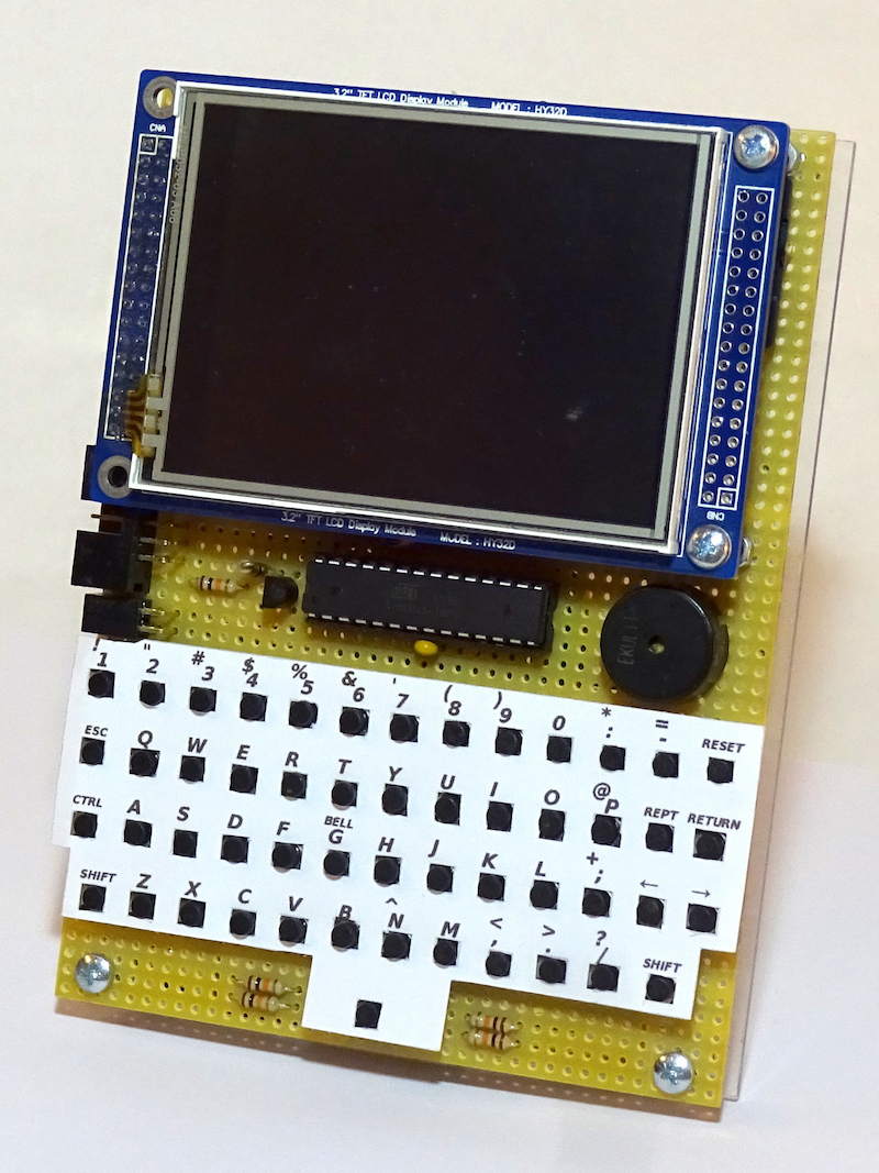
Human Motion Powered Nanotechnology Devices

Michigan State University researchers have came up with a new method for  harvesting energy from human motion using nanotechnology. They designed a low-cost film-like device, a nanogenerator, than can power a LCD display,  keyboard, and some LEDs without any source of electric power, by only using some human touching or pressing.

This device called FENG, biocompatible ferroelectret nanogenerator, consists of several thin layers of silicon wafer made of environmentally friendly substances like silver, polyimide, and polypropylene ferroelectret – which is introduced here as the active material of this device. To add the electrical powering feature, researchers added ions to each layer to make sure that each layer has its own charged particles. Finally the circuit works only once some pressure or mechanical energy is performed on the device. For example, by using this technology you will be able to power the LED lights with the pressure of your palm, while the pressure of your finger is enough to power the LCD screen.

In this video 20 LEDs are powered with hand pressing:

https://www.youtube.com/watch?v=cBGFTb-wwkI

Researchers’ investigations had shown that the voltage and current generated by pressure can be doubled if the device is folded, means a high-frequency pressure is already demonstrated.

“Each time you fold it you are increasing exponentially the amount of voltage you are creating,” said Nelson Sepulveda, associate professor of electrical and computer engineering and lead investigator of the project. “You can start with a large device, but when you fold it once, and again, and again, it’s now much smaller and has more energy. Now it may be small enough to put in a specially made heel of your shoe so it creates power each time your heel strikes the ground.”

Sepulveda believes that implementing this technology in real life will shift wearables to be completely powered by human motion. He and his team are working now on transmitting the power generated from the heel strike to be used for powering other devices like a headset.

In this video you can take a look at the flexible keyboard they designed:

https://www.youtube.com/watch?v=_-kkkNdbils

This research was funded by the National Science Foundation. You can learn more about this project by checking the scientific paper, and the university official website.

STEP/DIR SIGNAL TO CW/CWW SIGNAL CONVERTER FOR CNC & MOTION CONTROL SYSTEMS

Simple Circuit converts Step/Dir. signal into to double drive CW/CWW Pulse, Mach3 and few Hobby CNC software’s provides Step/Direction pulse output to drive stepper motor drivers.

Various AC servo works with double CW/CCW pulse. This circuit is solution to interface such AC CW/CCW pulse based driver with Mach3 or other CNC software’s. Circuit designed around 7408 and 7404 IC, board support 5V or 24V supply. Open Collector output can be interface with 24V system by changing output resistors.

Features

  • Supply 7V 24V DC
  • On Board Power LED
  • Inputs and Outputs Header Connector
  • On Board ERTH (Earth) Signal provided for chassis ground to avoid any noise

STEP/DIR SIGNAL TO CW/CWW SIGNAL CONVERTER FOR CNC & MOTION CONTROL SYSTEMS – [Link]

STEP/DIR SIGNAL TO CW/CWW SIGNAL CONVERTER FOR CNC & MOTION CONTROL SYSTEMS

Simple Circuit converts Step/Dir. signal into to double drive CW/CWW Pulse, Mach3 and few Hobby CNC software’s provides Step/Direction pulse output to drive stepper motor drivers.

Various AC servo works with double CW/CCW pulse. This circuit is solution to interface such AC CW/CCW pulse based driver with Mach3 or other CNC software’s. Circuit designed around 7408 and 7404 IC, board support 5V or 24V supply. Open Collector output can be interface with 24V system by changing output resistors.

Features

  • Supply 7V 24V DC
  • On Board Power LED
  • Inputs and Outputs Header Connector
  • On Board ERTH (Earth) Signal provided for chassis ground to avoid any noise

Note : Output Transistor can drive Stepper Drive or Servo driver Opto-couplers directly , choose appropriate collector resistor value for 5V or 24V

  • R3,R5,R9 470 Ohms for 5V DC Open Collector Output
  • R3,R5,R9 2K2 Ohms for 24V DC Open Collector Output

 Inputs:

  1. Step Pulse ( TTL 5V)
  2. Direction Pulse ( TTL 5V)
  3. Enable Signal ( TTL 5V )

Outputs:

  1. CW (5V Or 24V Open Collector)
  2. CWW ( 5V Or 24V Open Collector )
  3. Enable ( 5V Or 24V Open Collector )

Schematic

Parts List

Signal Diagram

Emulate an Apple ][ on an AVR Microcontroller

The Apple II personal computer, which stylized as Apple ][, is an 8-bit home computer and one of the first highly successful mass-produced microcomputer products. It was designed primarily by Steve Wozniak and developed with Steve Jobs. Apple ][ was introduced in 1977 at the West Coast Computer Faire by Jobs and was sold several million times till 1993.

Maximilian Strauch is a computer scientist, software developer, web designer and maker from Germany. In 2014 he wrote about implementing a software emulator for the complete Apple ][ computer system on a single Atmel AVR microcontroller unit (MCU) in his Bachelor thesis.

The microcontroller not only emulates the MOS 6502 processor, it also performs other tasks such as output display and input keyboard. A challenging task is to get the 20 MHz AVR controller run as the 1 MHz processor.

The final result of the thesis is a fully functional, battery powered and portable Apple ][ emulator.

This video shows the final prototype in action and demonstrates most of it’s features.

The layer diagram of the Apple ][ emulator consist of about 10 layers shown in the next figure.

  • Emulator Runtime Environment (ERE): Contains the source code which makes up the main (backend) GUI of the emulator in particular, the menus.
  • UI Framework / Display I/O: Some low level functions to control the LCD display (SSD 1289 controller) and functions to paint menus and backgrounds.
  • Keyboard I/O: Accepts key presses from the separate keyboard controller and provides some high-level functions to convert Apple ][ keystrokes into regular ASCII keycodes and some wait-for-keypress functions.
  • State I/O: The emulator supports saving the current state of the entire emulation including RAM and the processor registers. Therefore the execution can be saved and reloaded later to continue at the exact same execution state.
  • TWI / EEPROM: Provides physical layer support to talk to an EEPROM, e.g. two functions which utilize the AVR’s hardware support for I2C to talk to the 128KB I2C serial EEPROM from Microchip.
  • DSK I/O: Contains all high-level functions to read Apple ][ floppy disk images (5 1/2 inch floppy disks, normally 140 KB in total) and list that contained programs to load them into memory.
  • SD Library (3rd party): The emulator uses the Petit FAT File System Module by Elm Chan since it works out of the box. A further improvement could be to store states to the SD card.
  • 6502 CPU Emulation: Advanced emulation of the MOS 6502 processor without support for illegal instructions (not originally defined) and the BCD mode.
Layer diagram of the Apple ][ emulator: every horizontal connection of two boxes symbolizes a use relation.

Max has published detailed information about the thesis here. All of the project resources are available online, so you can download the full thesis, the keynote, and the schematic.

Software Defined Radio IC Decap

Software Defined Radio teardown: R820/RTL2832U Decap

Recently there has been much interest in two integrated circuit which were originally designed to receive FM radio and DVB-T TV (as used in Europe).
Some enterprising people quickly realised that since they were based on software-defined techniques they could be quickly re purposed for all sorts of clever things.

Software Defined Radio IC Decap – [Link]

How to Set Up and Program an LCD Display on an Arduino

circuitbasics.com writes:

In this tutorial, I’ll explain how to set up an LCD display on an Arduino, and show you all the functions available to program it (with examples). The display I’m using here is a 16×2 LCD display that I bought for under $10 on Amazon. LCDs are really useful in projects that output data, and they can make your project a lot more interesting and interactive.

How to Set Up and Program an LCD Display on an Arduino – [Link]

1K LCD Tinyfont

A tiny pixel font rendered to an LCD display, in under 1K program space. by Zach:

For the Hackaday 1k challenge, I’m attempting to pack a small pixel-based font and rendering to LCD in under 1K.

The project has already been developed in C, but the file size was much larger. This is rewrite in assembly.

Developed on an Atmega328p using a display from a Nokia 5110 on a Sparkfun dev board.

1K LCD Tinyfont – [Link]

Arduino Capacitance Meter Using TM1637

In this instructable by gustavio101 you will know how to make a capacitance meter using Arduino displayed on the TM1637 display with a range from 1 uF to 2000 uF.

To build this project you need the following parts:

    • Resistors
      1x: 220 Ohm
      1x: 10 kOhm, 8000 Ohms also would work depending on your code
    • Capacitors
      You need some capacitors to calibrate your meter, you can use 0 uF, 47 uF, 220 uF and 1000 uF
    • TM1637
      A chip for driving 7-segment displays. Using it in this project is optional, only if you wish to see the results on a small screen. You need also 8 jumper wires to wire the whole circuit including TM1637.
    • Arduino & USB cable

In order to connect the circuit, first you have to connect the 220 Ohm resistor to A0 and pin 11, the 10K Ohm should be connected between the A1 and pin 13, giving the hardware core structure of the meter. The anode of you capacitor should be placed where the A0 and A1 pin are connected, and the cathode to the GND as shown in this picture.

By uploading this code to your Arduino everything will be set! You only need to include the TM1637 library and the code necessary to view your work. Once you open the Arduino IDE open the two files together to have everything done.

#include "TM1637.h"

#define analogPin      0          
#define chargePin      13         
#define dischargePin   11        
#define resistorValue  10000.0F
#define CLK 9
#define DIO 8

TM1637 TM(CLK, DIO);

unsigned long startTime;
unsigned long elapsedTime;
float microFarads;                

void setup()
{
  pinMode(chargePin, OUTPUT);     
  digitalWrite(chargePin, LOW);  
  Serial.begin(19200);
  TM.init();
  TM.set(BRIGHT_TYPICAL);
  delay(1500);             
}

void loop()
{
  digitalWrite(chargePin, HIGH);  
  startTime = millis();
  while(analogRead(analogPin) < 620){       
  }

  elapsedTime= millis() - startTime;
  microFarads = ((float)elapsedTime / resistorValue) * 1000;   
  Serial.print(elapsedTime);       
  Serial.print(" mS    "); 


  if (microFarads >= 1000)
        {
          Serial.print((long)microFarads);       
          Serial.println(" microFarads");
          int value = microFarads;
          int DigitOne = value / 1000;
          int DigitTwo = ((value / 100) % 10);
          int DigitThree = ((value / 10) % 10);
          int DigitFour = value % 10;
          TM.display(0, DigitOne);
          TM.display(1, DigitTwo);
          TM.display(2, DigitThree);
          TM.display(3, DigitFour);
        }
  else
  {    
  if ( microFarads >= 100)
        {
          Serial.print((long)microFarads);       
          Serial.println(" microFarads");
          int value = microFarads;
          int DigitOne = value / 100;
          int DigitTwo = ((value / 10) % 10);
          int DigitThree = value % 10;
          TM.display(1, DigitOne);
          TM.display(2, DigitTwo);
          TM.display(3, DigitThree);
        }
      else
      {
        if (100 > microFarads >= 1)
        {
          Serial.print((long)microFarads);       
          Serial.println(" microFarads");
          int value = microFarads;
          int DigitOne = value / 10;
          int DigitTwo = value % 10;
          TM.display(0, 0);
          TM.display(1, 0);
          TM.display(2, DigitOne);
          TM.display(3, DigitTwo);
        }
          else
          {          
           delay(500); 
          }        
     }
  }
     
  digitalWrite(chargePin, LOW);            
  pinMode(dischargePin, OUTPUT);            
  digitalWrite(dischargePin, LOW);          
  while(analogRead(analogPin) > 0){         
  }


  pinMode(dischargePin, INPUT);            
} 

Check gustavo101’s instructable to know more details and also the project that inspired him to do this one!

TOP PCB Companies