A scalable development kit integrates ST SensorTile with Valencell’s Benchmark biometric sensor system to accelerate smart wearable and IoT product development. By Graham Prophet @ edn-europe.com
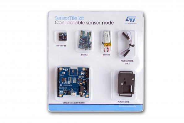
Valencell (Raleigh, North Carolina) is a company active in high-performance biometric data sensor technology; in a joint announcement with STMicroelectronics the two companies have disclosed an accurate and scalable development kit for biometric wearables that includes ST’s compact SensorTile turnkey multi-sensor module integrated with Valencell’s Benchmark biometric sensor system. Together, SensorTile and Benchmark comprise the most useful portfolio of sensors to support the most advanced wearable use cases, according to their designers.
Biometric sensor platform for wearables and IoT – [Link]
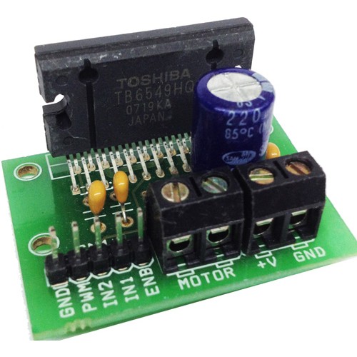
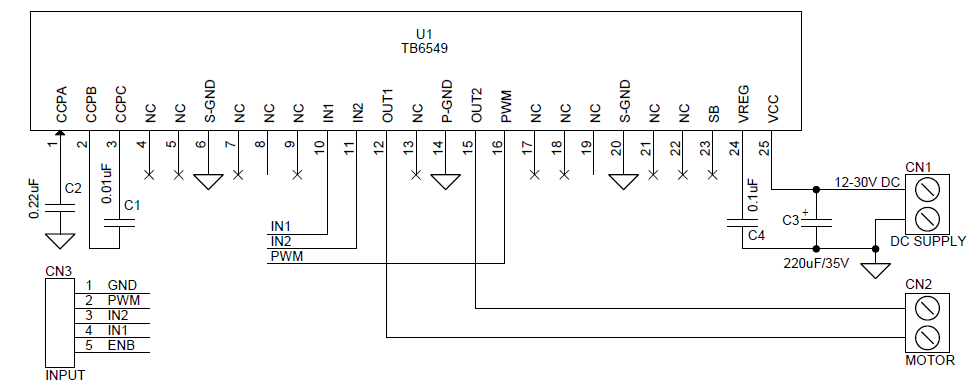
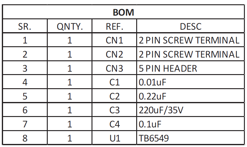
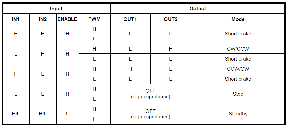
The H-Bridge Motor Driver Module Based on TB6549HQ IC from Toshiba, is a full-bridge driver IC for DC motors that uses an LDMOS structure for output transistors. High-efficiency drive is possible through the use of a MOS process with low ON-resistance and a PWM drive system. Four modes, CW, CCW, short brake, and stop, can be selected using IN1 and IN2. Supply input 12V to 30V DC and Maximum Load 4.5Amps.
Specifications
Power supply voltage: 30 V (max)
Output current 4.5 A
Low ON-resistance: 1.0 Ω (up + low/typ.)
PWM control capability
Standby system
Function modes: CW/CCW/short brake/stop
Built-in overcurrent protection
Built-in thermal shutdown circuit
4.5A H-Bridge DC Motor Driver Module Using TB6549HQ – [Link]
The H-Bridge Motor Driver Module Based on TB6549HQ IC from Toshiba, is a full-bridge driver IC for DC motors that uses an LDMOS structure for output transistors. High-efficiency drive is possible through the use of a MOS process with low ON-resistance and a PWM drive system. Four modes, CW, CCW, short brake, and stop, can be selected using IN1 and IN2. Supply input 12V to 30V DC and Maximum Load 4.5Amps.
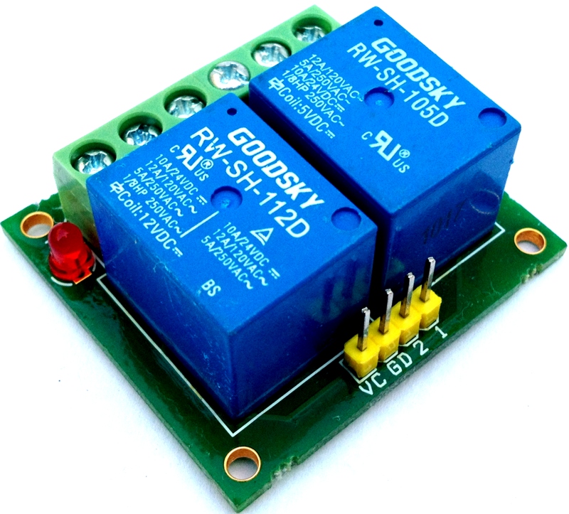
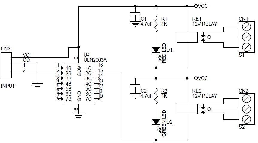
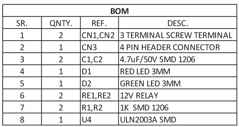
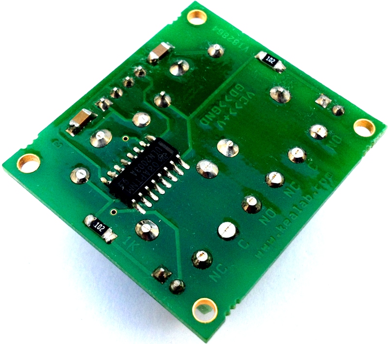
Dual channel Compact Relay driver module can be controlled by feeding 2-12V trigger voltage, Very useful project for application like Micro-Controller based projects, Remote controller, Lamp on Off, and any circuits which required isolated 5A current and high voltage switching by applying any TTL or CMOS level voltage. Two LED works as operation indicator, 3 pins screw terminals to connect load. Relay provides both normally open and normally closed switching.
Note: Board is made only for low voltage switching applications.
Specifications
Input: 12 VDC @ 84 mA
Output: Two SPDT relay
Relay specification: 5 A @ 60 VAC
Trigger level: 2 to 12 VDC
Header connector for connecting power and trigger voltage
LED on each channel indicates relay status
Power Battery Terminal (PBT) for easy relay output connection
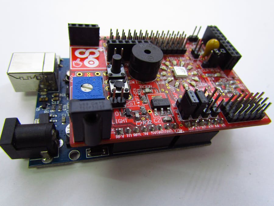
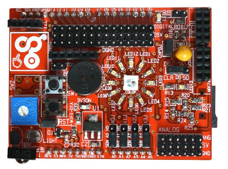
The Idiotware Shield is a learning platform that offers both novices and advanced Arduino users
the opportunity to bring hundreds of projects to life quickly. it offers a large variety of wireless communication options, input sensors, outputs, storage and device extensibility.
The idIoTware shield has a built in lm35 sensor that has a sensitivity of 10mV / oC, that means according to this equation: Temperature ( oC) = Vout * (100 oC/V)
That if Vout is 0.5V , then, Temperature = 50 oC. However, this built-in sensor gives a higher analog voltage on pin A0 if a higher temperature was applied.
To set up the IdIoTware shield you need to connect LM35 sensor to SEL0 3 pin header by using a jumper. The SD card should be connected to D6 and SD pin header, thus we need antoher jumper to enable it.
By uploading this code to your Arduino, you will create a CSV file with every one minute for 15 minutes. The temperature will be logged to the file thanks to the SdFat library used. You can edit the rate and duration as you prefer.
/* The circuit: * LM35 sensor on analog pin A3 * SD card attached to SPI bus as follows: ** MOSI - pin 11 ** MISO - pin 12 ** CLK - pin 13 ** CS - pin 4 */#include <SPI.h>#include <SdFat.h>
SdFat sd;
constuint8_t chipSelect =6;
//const int chipSelect = 4; //cs pin of SD card shieldint tempPin = A3; // LM 35 is connected to A3 pin.int buzzerPin = A2; // buzzer is connected to A2 pin
File dataFile; // the logging filechar filename[] ="Temp000.CSV";
float tempInCelcius;
float tempInFarenheit;
unsignedlong time=0;
int samplingTime =10; //this variable is interval(in Seconds) at which you want to log the data to SD card.int duration =15; //this variable is duration(in Minutes) which is the total time for which you want to log data.voidsetup()
{
// Open serial communications and wait for port to open:
Serial.begin(9600);
while (!Serial)
{
; // wait for serial port to connect. Needed for native USB port only
}
Serial.print("Initializing SD card...");
// see if the card is present and can be initialized:if (!sd.begin(chipSelect))
{ sd.initErrorHalt();
Serial.println("Card failed, or not present");
// don't do anything more:return;
}
Serial.println("card initialized.");
// create a new filefor(unsignedint i =0; i <1000; i++)
{
filename[4] = i/100+'0';
filename[5] = ((i%100)/10) +'0';
filename[6] = i%10+'0';
if(! sd.exists(filename))
{
// only open a new file if it doesn't exist
dataFile = sd.open(filename, FILE_WRITE);
break; // leave the loop!
}
}
if(! dataFile)
{ //alert user
Serial.println("couldnt create file");
int alertAlarm1[] = { 1000,1000,1000,1000,1000,1000,1000,1000,1000,1000,
1000,1000,1000,1000,1000,1000,1000,1000,1000,1000,};
int noteDurations[] = { 5,5,5,5,5,5,5,5,5,5,5,
5,5,5,5,5,5,5,5,5,5,5 };
for (int thisNote =0; thisNote <20; thisNote++)
{
// Duration = 1 second / note type// e.g. quarter note = 1000 / 4, eighth note = 1000/8, etc.int noteDuration =2500/ noteDurations[thisNote];
tone(A2,alertAlarm1[thisNote], noteDuration);
//pause for the note's duration plus 100 ms:
delay(noteDuration +100);
}
}
Serial.print("Logging to: ");
Serial.println(filename);
dataFile = sd.open(filename, FILE_WRITE);
// if the file is available, write to it:if (dataFile)
{
dataFile.print("Logging Temperature for ");
dataFile.print(duration);
dataFile.print(" minutes at interval of ");
dataFile.print(samplingTime);
dataFile.println(" seconds.");
dataFile.close();
}
// check availble space on SD Carduint32_t freeKB = sd.vol()->freeClusterCount();
freeKB *= sd.vol()->blocksPerCluster()/2;
Serial.print("Free space KB: ");
Serial.println(freeKB);
uint32_t freeMB= freeKB/1024;
Serial.print("Free space in MB: ");
Serial.println(freeMB);
if(freeKB <=500)
{
Serial.println("LOW SPACE!!!");
int alertAlarm2[] = { 1000,1000,1000,1000,1000,1000,1000,1000,1000,1000,1000,1000,1000,1000,1000,
1000,1000,1000,1000,1000,1000,1000,1000,1000,1000,1000,1000,1000,1000,1000};
int noteDurations[] = { 15,15,15,15,15,15,15,15,15,15,15,15,15,15,15,
15,15,15,15,15,15,15,15,15,15,15,15,15,15,15 };
for (int thisNote =0; thisNote <20; thisNote++)
{
// Duration = 1 second / note type// e.g. quarter note = 1000 / 4, eighth note = 1000/8, etc.int noteDuration =2500/ noteDurations[thisNote];
tone(A2,alertAlarm2[thisNote], noteDuration);
//pause for the note's duration plus 50 ms:
delay(noteDuration +50);
}
}
duration *=60; //convert durartion in minutes to seconds
}
voidloop()
{
dataSamples(); // here we are logging data at interval of 1 minute for 15 mintutes, i.e, 15 samples.// if you want to save data for 2 hours then simply multiply 2 by 60 which will give // you value of 120 minutes then use 120 as second parameter.
}
// this method will log data to SD card at particular interval and for paricular durationintdataSamples()
{
// here we are logging data at interval of 1 minute for 15 mintutes, i.e, 15 samples.// if you want to save data for 2 hours then simply multiply 2 by 60 which will give // you value of 120 minutes then change the varible duration to 120.
tempInCelcius = ( 5.0* analogRead(tempPin) *100.0) /1024.0;
// uncomment following line to get temperature values in Farehniet//tempInFarenheit = ((tempC*9)/5) + 32; //convert celcius to farenheitunsignedlong elapsedTime = millis()/1000; // this variable will keep track of elapsed timewhile(((millis()/1000)-elapsedTime) <1); // this loop will do nothing until a second has passed
time++; //increment time after each second.if((duration >= time) && (time % samplingTime ==0))
{
LogToSDcard(); //Log to SD using commands under void LogToSD() // print to the serial port too:
Serial.print("Temperature: ");
Serial.print(tempInCelcius);
Serial.print(char(176));
Serial.println("C");
}
}
voidLogToSDcard()
{
// open the file. note that only one file can be open at a time,// so you have to close this one before opening another.
dataFile = sd.open(filename, FILE_WRITE);
// if the file is available, write to it:if (dataFile)
{
dataFile.print(tempInCelcius);
dataFile.println("°C");
dataFile.println(",");
dataFile.close();
// to print temperature values in Farehniet uncomment following code. /* dataFile.print(tempInFarenheit); dataFile.print("°C"); dataFile.println(","); dataFile.close(); */
}
//if the file isn't open, pop up an error:else
{
Serial.println("error opening datalog.txt");
delay(2000);
}
}
As soon you get the CSV file copied from the SD card, you can visualize the data in graphs.
This video by IdIoTware team demonstrates how to build this project in details, check it out:
You can check the project’s page for more information and detailed tutorial.
In this video, I go through the process of calibrating an LCD touchscreen on the Raspberry Pi. Calibrating the LCD touchscreen should be done after installing it to make it more responsive and accurate.
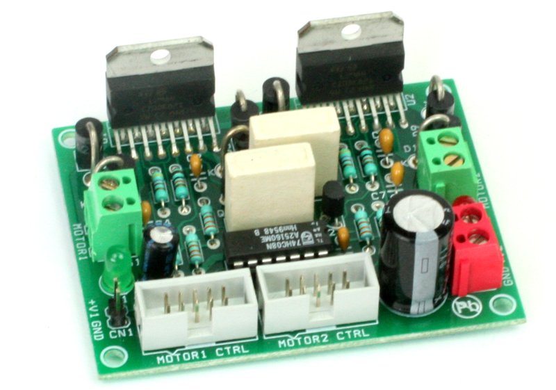
2x L298 H-Bridge Dual Motor driver project can control two DC motors connected to it. The circuit is designed around popular dual H-Bridge L298 from ST. Motor supply 7V To 46V DC, Load 2Amp Each Channel.
Features
Motor supply V2: 7 to 46 VDC
Logic Supply V1 : 5V DC
Input Signal: Enable, Dir. , PWM
Board Provides Current Feed Back ( On Board Shunt Resistor)
Control Logic Input: Standard TTL logic level
Output DC drive to motor: up to 2A + 2A
External Diode Bridge for protection
On Board 5V Power LED
On Board Motor Supply LED
10X Box Header Connector for Inputs and PWM
Header Connector For Logic Supply
Screw Terminal for Motor Connections
Screw Terminal For Motor Supply
2X L298 Dual DC Motor Driver Board for Robots – [Link]
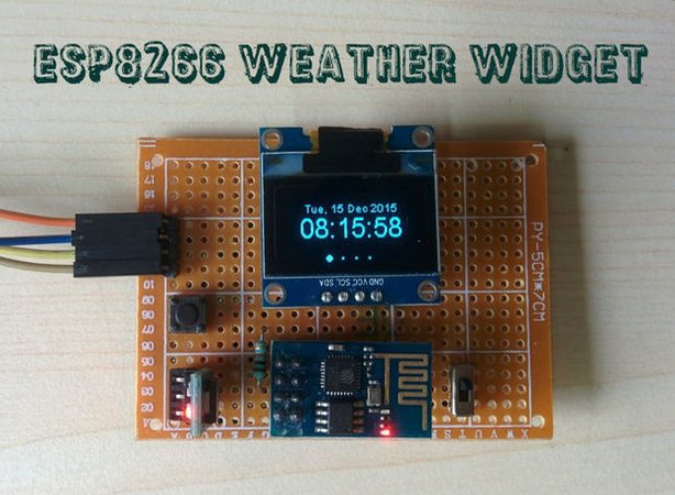
deba168‘s new instructable is a weather widget: “an application that can be downloaded on your PC, laptop or a mobile device and perform the job of providing easy access to weather information”
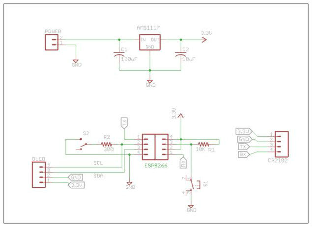
It’s an ESP8266 based weather display unit which retrieves localized weather information from http://www.wunderground.com by WLAN and displays it on a 128×64 OLED display. It displays the current time with date, some weather information like temperature, pressure, humidity and rainfall, and finally the forecasting for the next 3 days.
Check this demo video:
In order to build this project you need the following parts:
The project’s maker advises you to follow his steps in the code inside this zip file to avoid any problems in compiling.
For obtaining data from the Weather Underground , you need to get an API key through signing up in the website and purchasing one. Once you clarify that you won’t use it for commercial use, you won’t be asked for any pay methods.
To make sure that the code will work correctly, you have to change the following things.
Enter the Wunderground API Key
Enter your Wifi credentials
Adjust the location according to Wunderground API
Adjust UTC offset
The final step will be programming the ESP8266 module using FTDI programmer.
Check this video for more information and to see the project in action:
Battery technologies of all chemistry are experiencing revolutionary changes nowadays. Nanotechnology is leading this revolution by yielding new battery technologies including but not limited to Tiny Supercapacitors and Li-ion batteries that never explode at any condition. But, it’s bothersome to make different chargers for different types of batteries. So, Microchip solved this problem by introducing a new hybrid PWM controller, MCP19124/5, that charges batteries of any chemistry.
MCP19124 PWM Controller – 24 Pin QFN Package
The power of this charging device lies in the combination of an 8-bit PIC microcontroller and an analog PWM controller in one package. This mixed signal low-side PWM controller features individual analog PWM control loops for both current regulation and voltage regulation. It can be configured with separate feedback networks and reference voltages. Any voltage, current, temperature, or duration can be used to trigger a transition to a different charging profile.
Various types of batteries require different charging profile. So, the only way to charge all kinds of batteries with a single device is to simulate all the charging profiles. A user can set his/her desired profile with the help of two independent current and voltage control loops, along with variable reference voltage. Now let’s get to know more details about this versatile PWM controller IC.
The MCP19124/5 is a mid-voltage (4.5-42V) analog-based PWM controller with an integrated 8-bit PIC Microcontroller. There are two devices, the MCP19124 and MCP19125, where the last one has four I/O pins more than the first one. MPC19124 and MPC19125 are packaged in 24-lead QFN package and 28-lead QFN package respectively. It has following features:
Smooth, dynamic transitions from constant-current to constant-voltage operation
Dynamically adjustable output current and output voltage over a wide operating range
Wide operating voltage range: 4.5-42V
Analog peak-current mode Pulse-Width Modulation (PWM) control
Available fixed frequency (31 kHz to 2 MHz)
I2C communication interface
9 GPIO for MCP 19124 and 12 GPIO for MCP19125
Integrated high voltage linear regulator, with external output
Integrated temperatures sense diode
Integrated 10 bit A/D converter
Minimal external components needed
Custom algorithm support
Topologies supported include Boost, SEPIC, Flyback, and Cuk
In fact, the above list is just a brief overview. The controller is so complicated that user must read all 236 pages of the datasheet to gain sufficient knowledge.
Now, the question is, how can we use this IC to design an efficient battery charger?
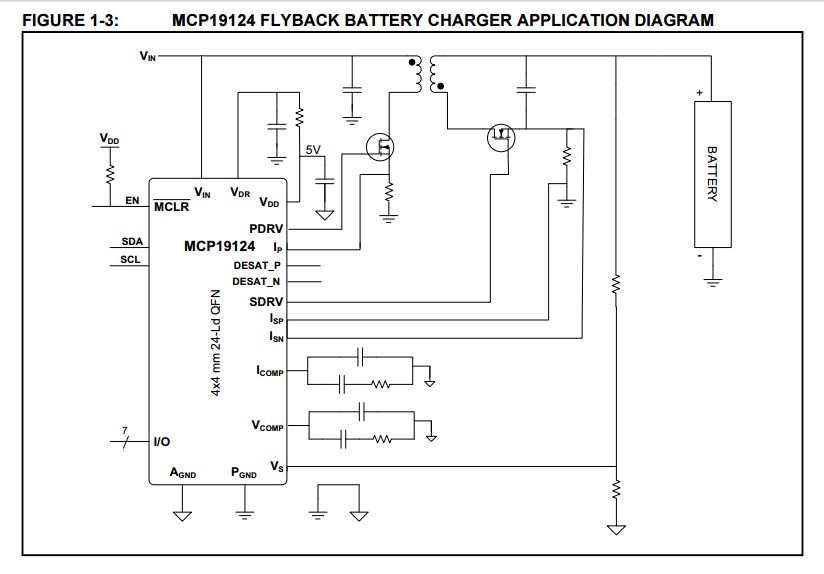
To find the answer, one must read the datasheet thoroughly. At the same time, in-depth knowledge about the target battery is also required. However, Microchip provided a few schematics (as references) in the datasheet based on different applications. The circuit on battery charger is given below:
Battery Charger Circuit Using MCP19124 IC
This ultimate powerful dual-loop PWM controller is going to be a game changer and part of the battery technology revolution. It possesses lots of possibilities. To learn more about this fantastic hybrid controller, study the datasheet carefully.