After electing to use the PING))) sensor exactly as directed, I needed to build the rest of my circuit. I wanted to build something robust that would mount nicely on the wall of my dad’s garage. Figuring that the sensor would likely need to be placed down low by the car’s bumper, I decided on a two-component design consisting of a small sensor and a large visible display that could be mounted at eye-level.
The PNP transistor is a mystery to many. But it doesn’t have to be. If you want to design circuits with transistors, it’s really worth knowing about this type of transistor. by Oyvind @ build-electronic-circuits.com
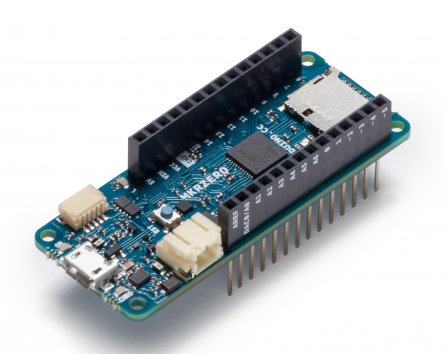
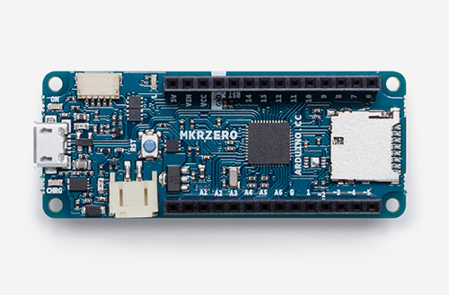
Arduino had announced a new member of its family: MKRZero! This new board comes with the size of 61x25mm MKR1000 board and the power of ARM-core Arduino Zero.
The ARM-core board consists of an on-board SD connector with dedicated SPI interfaces (SPI1) that make it easy to browse your files with no extra hardware.
You can power your MKRZero using a micro-USB cable or a LiPo battery, but you should pay attention that the operation voltage is 3.3.V and applying higher voltages to any I/O pin will ruin the board. To guarantee the voltage, you can use a battery and monitor it using analog converter.
The small size, low power consumption, integrated battery management, and integrated SD management are some of the advantages of this great tiny board.
MKRZero has 22 digital I/O pins, 12x PWM, 1x UART, 1x SPI, 1x I2C,32x LED_BUILTIN, 7x analog input pins, 1x analog output and 8x external interrupts. Here are the hardware specifications:
Supported Battery: Li-Po single cell, 3.7V, 700mAh minimum
DC Current for 3.3V Pin: 600mA
DC Current for 5V Pin: 600mA
Circuit Operating Voltage: 3.3V
DC Current per I/O Pin: 7 mA
Flash Memory: 256 KB
Flash Memory for Bootloader: 8 KB
SRAM: 32 KB
Clock Speed: 32.768 kHz (RTC), 48 MHz
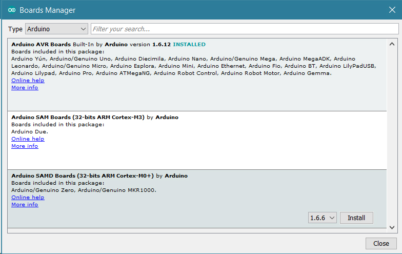
If you program your boards using Arduino Web Editor then everything is set. But to program MKRZero using Arduino IDE, you need to update the IDE by adding the new Intel SAMD Core by selecting Tools> Boards Manager as shown in the picture.
Due to its small size, MKRZero is said to be the best fit for your next innovative projects in wearable technology, high-tech automation, robotics, and much more. Some tutorials for projects using MKRZero are available now on Arduino project hub.
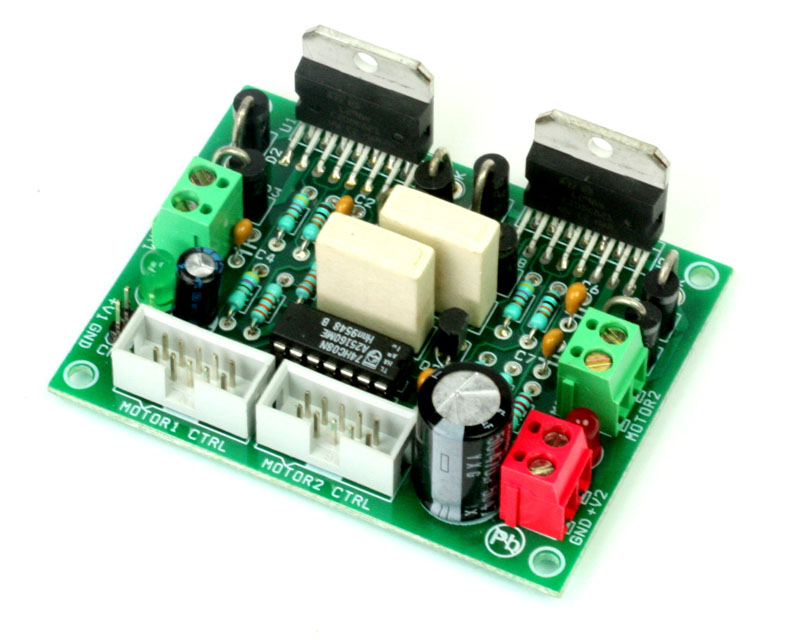
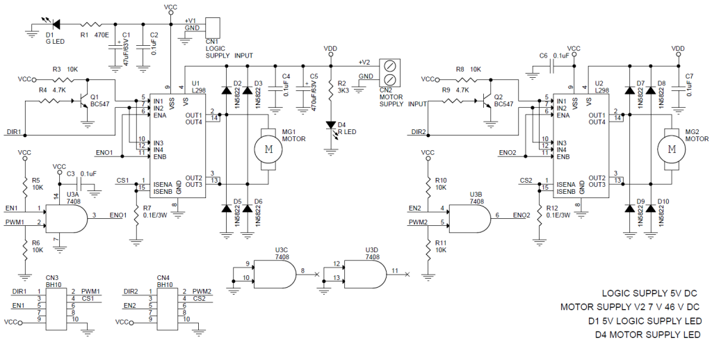
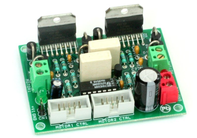
2XL298 H-Bridge Dual Motor driver project can control two DC motors connected to it. The circuit is designed around popular dual H-Bridge L298 from ST. Motor supply 7V To 46V DC, Load 2Amp Each Channel.
Features
Motor supply V2: 7 to 46 VDC
Logic Supply V1 : 5V DC
Input Signal: Enable, Dir. , PWM
Board Provides Current Feed Back ( On Board Shunt Resistor)
Making an electronic dice is very popular among hobbyists and there are already lots of ready-made projects on the internet about this topic. Tim at Hackaday.io designed an electronic dice project for “1KB Limit” competition. But why another dice project while the internet is already crowded with similar things?
Well, it’s not the subject of this project, but the concept, which makes it unique. This is the most miniaturized dice one can make. As Tim says:
It makes use of a very efficient multiplexing scheme to drive all the 7 LEDs of an electronic die with only two I/O pins.
Yes, you’ve read it right. Only two I/Os are used to control all 7 LEDs of a die. It became possible for a super-efficient multiplexing scheme – Charlieplex Plus. The main goal of this project is introducing you to Charlieplex Plus.
DICE10 – The Tiny Electronic Die
Requirements:
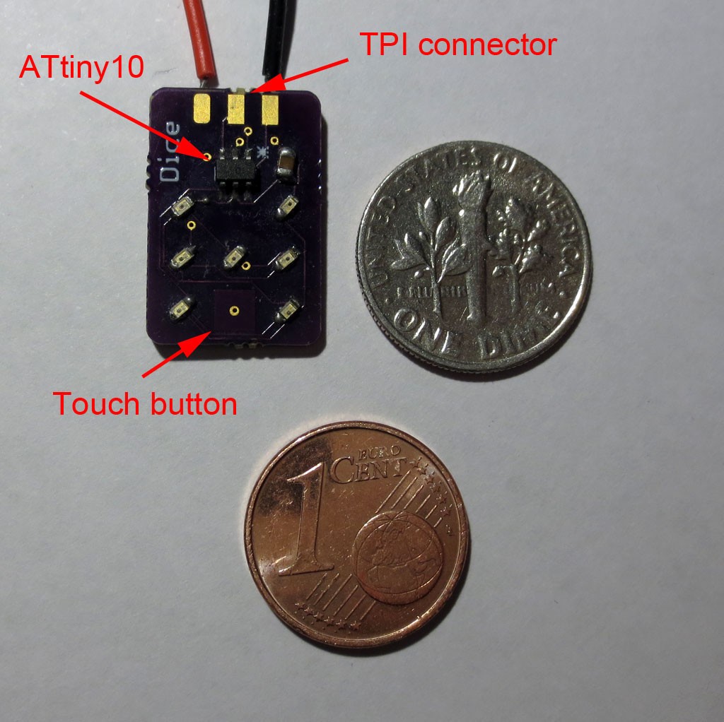
1 x ATtiny10
7 x SMD LED 0603
1 x SMD Capacitor 100n 0805
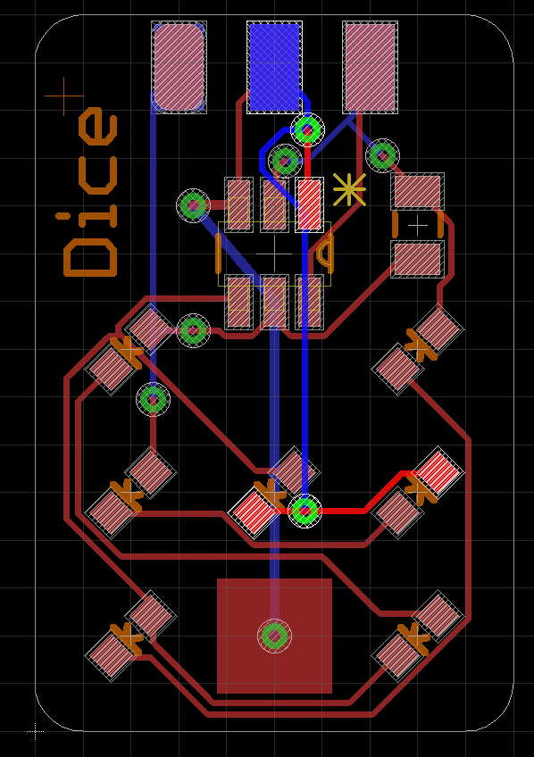
PCB of the Circuit
Please Note: SMD components are used to miniaturize the circuit. You can easily go for through-hole components if size is not a concern.
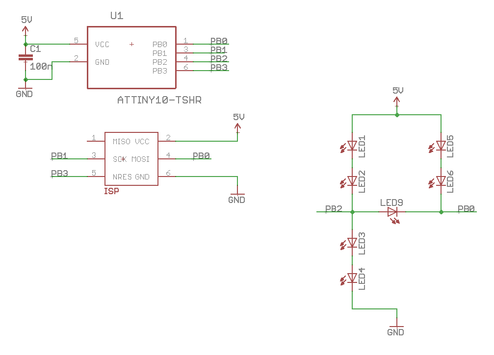
You can see from the circuit that connections are pretty straight forward. PB2 and PB0 are used to drive the LEDs. The remaining free I/O pin, PB1, is used as a touch sensor. PB1 is RESET pin, so it can’t be used as GPIO.
All components are squeezed into a PCB that is only 13 mm x 19 mm. Instead of 6 pin headers, edge connections are used for SPI/TPI interface in order to reduce the PCB size.
PCB Diagram Of DICE10
Design:
As an entry for Hackaday 1Kb competition, one vital target of this project was to keep the code size below 1Kb. Using an ATtiny10 as an MCU automatically limits the code size to 1kb, so the requirement is automatically met.
The firmware uses a timer interrupt to multiplex all the 7 LEDs. The main routine calls the TinyTouchLib to poll the touch button. If a button press is detected, the value of the die is changed in a random manner. Though due to smaller physical size, the touch button is somewhat unreliable and often detects multiple touches. But there is no problem in using it as a random number generator.
Multiplexing:
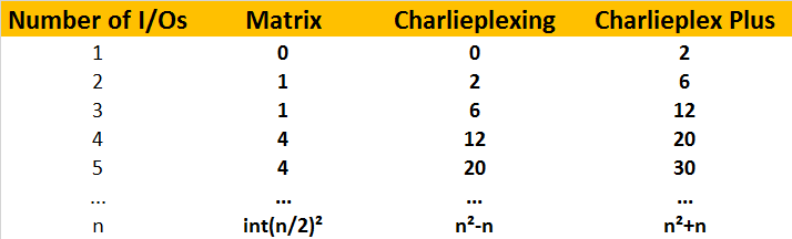
Now coming to the most interesting part of the design – the multiplexing scheme. A very common and efficient scheme is Charlieplexing. Impleneting charlieplexing you can control n²-n LEDs by n I/O lines.
Now, how can you control 7 LEDs of the die using only 2 I/O pins?
The dice pattern consists of 7 LEDs. However, you will quickly notice that 6 of these LEDs only light up in pairs, so that only 3 pairs of LEDs plus the middle one need to be controlled. This requires four I/Os – still too much!
Using Charlieplexing we can reduce the number of I/O lines to three. but still a bit too much for the ATtiny10, as an extra I/O line is required to “roll the die”. The only solution left is “Charlieplex Plus”. Before explaining that, let’s learn what Charlieplexing is.
Charlieplexing: Charlieplexing is a technique for driving a multiplexed display in which relatively few I/O pins on a microcontroller are used to drive an array of LEDs. Charlieplexing uses the tri-state property (neither HIGH nor LOW state) of microcontroller I/O pins. Only two I/Os are active at a time – one set to HIGH and one set to LOW – while all other pins are in a high resistivity state. LED connected between two active I/Os will light up.
Now, what if we activate only one I/O instead of two? Here comes Charlieplex Plus.
Charlieplex Plus:
Charlieplex Plus Circuit Example
The circuit above shows how to connect LEDs in this scheme. In addition to the antiparallel pair between the two I/O pins (PB2 and PB0), LEDs are also connected to VCC and GND. The sum of forward voltages of the four LEDs in series (LED1-4 and LED5-8) is higher than 5V so that they will not light up when PB0 and PB2 are in the high impedance (Z) state.
When either PB0 or PB2 is H or L and all other pins are Z, sufficient voltage is present to light up a pair of LEDs. However, when PB0 is HIGH and PB2 is LOW or vice versa, LED9 or LED10 will light up.
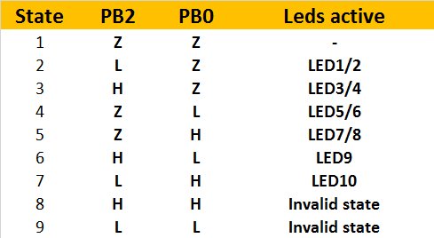
In fact, Charlieplex plus scheme is really hard to understand. It is impractical as well. But it’s still usable in such cases where our only option is to control lots of LEDs with lesser I/Os. Let’s look at the table to have a better understanding:
Charlieplex Plus Encoding Table
A general analysis shows that the new scheme can drive n²+n LEDs with n I/Os. The table below shows the number of LEDs than can be driven with a given number of I/Os with different multiplexing schemes.
Table of Comparison Between Different Multiplexing Schemes
So, in a summary, we can see that two I/Os are capable of handling three LEDs, and that’s what we need.
Conclusion:
In this article, the multiplexing scheme was the first priority. If you understand the scheme clearly, you can implement it in different projects. Read this blog post if you are willing to learn more on this.
This image shows how the DICE10 works:
Animated Image of DICE10
But remember that implementing Charlieplex Plus in any project is not recommended at all. It’ll make the design and the troubleshooting process extremely complex.
Researchers at the École Polytechnique Fédérale de Lausanne and the Centre Suisse d’Electronique et de Microtechnique have invented a new device to store solar power while the sun’s not shining by converting it into Hydrogen. Although many current methods use the same approach to store energy, but this device rivals them in stability, efficiency and cost.
They combined commercially available components that have already proven effective in industry, such as Nickel, in order to develop a robust and effective system, that is :made up of three interconnected, new-generation, crystalline silicon solar cells attached to an electrolysis system that does not rely on rare metals. The device is able to convert solar energy into hydrogen at a rate of 14.2%, and has already been run for more than 100 hours straight under test conditions.”
In order to develop this device, the researchers used layers of crystalline silicon and amorphous silicon to allow higher voltages. Thus, three cells in series generate a nearly ideal voltage for electrolysis.
“We wanted to develop a high performance system that can work under current conditions,” says Jan-Willem Schüttauf, a researcher at CSEM and co-author of the paper. “The heterojunction cells that we use belong to the family of crystalline silicon cells, which alone account for about 90% of the solar panel market. It is a well-known and robust technology whose lifespan exceeds 25 years. And it also happens to cover the south side of the CSEM building in Neuchâtel.”
This method, which outperforms previous efforts in terms of stability, performance, lifespan and cost efficiency, is published in the Journal of The Electrochemical Society. You can check the scientific paper here.
Let’s take a look, therefore, at the project’s electrical section, that is essentially composed of a set of 56 Neopixel LEDs, that have been arranged so to form two concentric stars; the first 35 RGB LEDs (out of 56) form the bigger, external star, while the other 20 ones form the smaller and internal star. The LED number 56 is placed exactly at the center of the printed circuit board, that has the shape of a five-pointed star.
The Neopixel LEDs are connected in cascade but powered in parallel; such a configuration enables to address each single LED and to individually choose the colour; among the possible hues, the 256 possible combinations for each primary colour (therefore we have 256x256x256 combinations!) determine a total of 16,777,216 colours: that’s what one would call true colours!
In this video tutorial educ8s.tv shows us how to load bitmap graphics in our Arduino Touch Screen projects using Adafruit’s GFX library.
The procedure that I am going to describe works with all the color displays that are supported by Adafruit’s GFX library and by the displays that use the TFTLCD library from Adafruit with a small modification. So from the displays I own I can use the color OLED display, the 1.8” ST7735 color TFT display, the 2.8” Color Touch Screen that I reviewed a few weeks ago and the 3.5” Color TFT display. You can find links for all the displays below.
Bitmap graphics on an Arduino Touch Screen and other top Arduino Displays – [Link]
A wide input range of 4.5 V to 40 V enables the TS3004x series of DC/DC synchronous buck regulators from Semtech to work in a wide range of applications, including industrial, telecommunication, and consumer. The current-mode TS30041 and TS30042 furnish 1 mA and 2 mA of continuous output current, respectively, and include integrated power switches and robust fault protection in a small 3×3-mm, 16-lead QFN package.
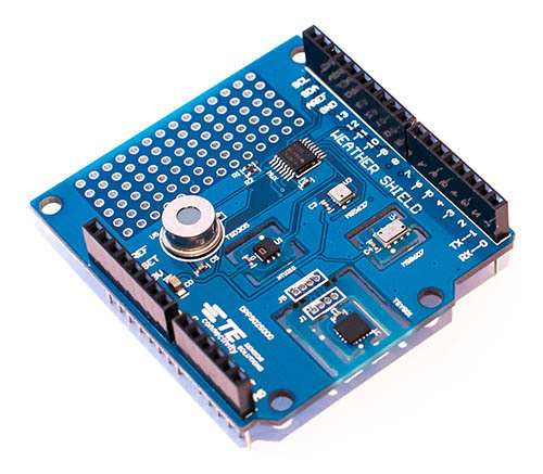
In a stint of list-o-mania TE Connectivity have slapped five environmental sensors on a single board called MEAS for plugging onto the Arduino/Genuino 101 and Uno R3. Here goes in telegram style.
MEAS: five weather sensors on one Arduino shield – [Link]