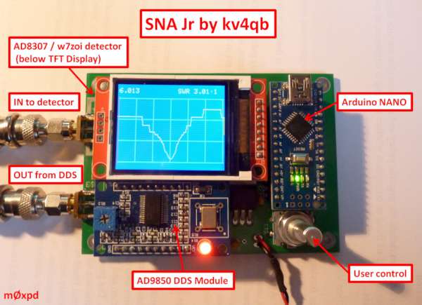
DuWayne’s project uses an AD9850 in one of our familiar modules to generate RF, under the control of an Arduino NANO. You can read on DuWayne’s blog how the SNA Jr is the descendant of earlier experiments in which an Si5351 was used as the signal source.
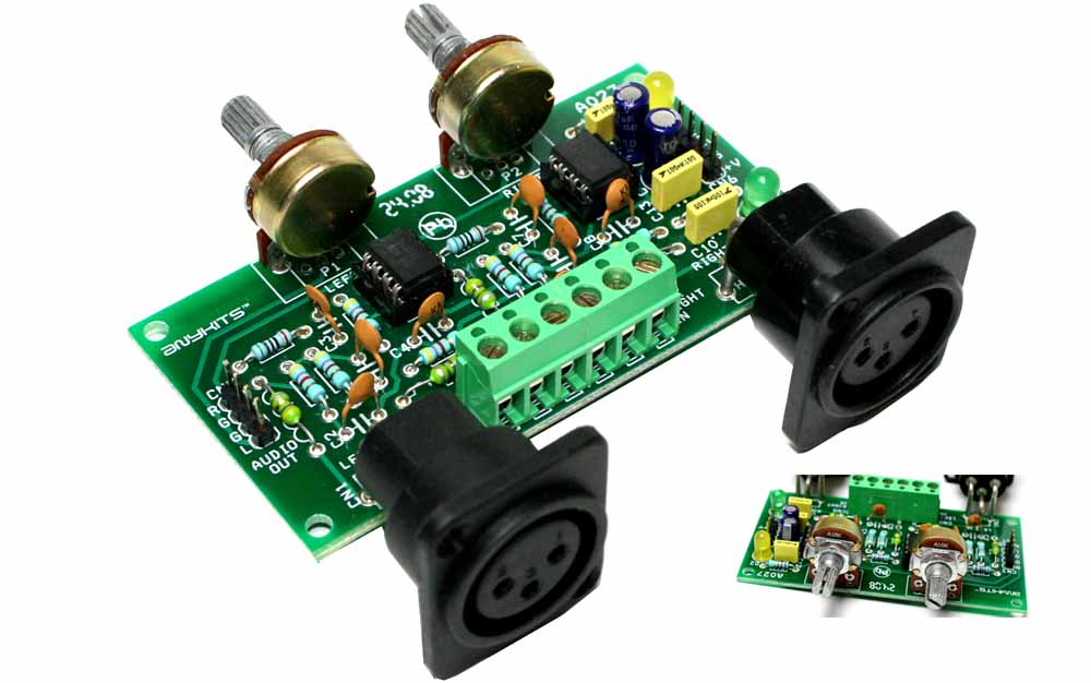
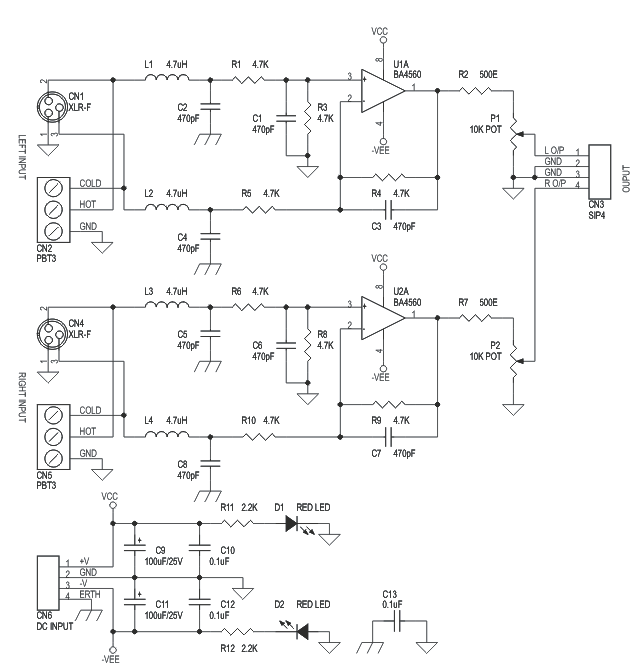
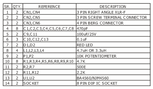
High quality low noise Balance to unbalanced converter designed around op-amps. The project can be used as balance to unbalance converter with on board audio level adjust potentiometer. The project work with +/-15V dual DC supply and draw approximately 100 mA. Board has separate screw terminal for Euro balance audio signal input connector. Dual LED provided for power indication. Input has RFI filter (Inductor)
Specifications
XLR connectors for stereo audio input
Screw terminal for Euro Balance audio input standard
circuitbasics.com show us how to connect Rasperry Pi using Ethernet cable.
If you use your Raspberry Pi as a gaming console, media server, or stand-alone computer, WiFi is a great way to get internet access. But if you connect to your Pi with SSH or a remote desktop application a lot, WiFi is actually one of the slowest and least reliable ways to do it. A direct ethernet connection is much faster and a lot more stable.
How to Connect to a Raspberry Pi with an Ethernet Cable – [Link]
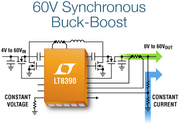
The LT8390, is a synchronous buck-boost DC/DC controller that can regulate output voltage, and input or output current from input voltages above, below and equal to the output voltage. Its 4V to 60V input voltage range and 0V to 60V output voltage range are ideal for voltage regulator, battery and supercap charger applications in automotive, industrial, telecom and even battery-powered systems. The LT8390’s 4-switch buck-boost controller, combined with 4 external N-channel MOSFETs, can deliver from 10W to over 400W of power with efficiencies up to 98%. Its buck-boost capability is ideal for applications such as automotive, where the input voltage can vary dramatically during stop/start, cold crank and load dump conditions. Transitions between buck, buck-boost and boost operating modes are seamless, offering a well regulated output even with wide variations of supply voltage. The LT8390 is offered in either a 28-lead 4mm x 5mm QFN or thermally enhanced TSSOP to provide a very compact solution footprint. [source]
By bringing the power of open-source and agile hardware design to the semiconductor industry, SiFive aims to increase the performance and efficiency of customized silicon chips with lower cost.
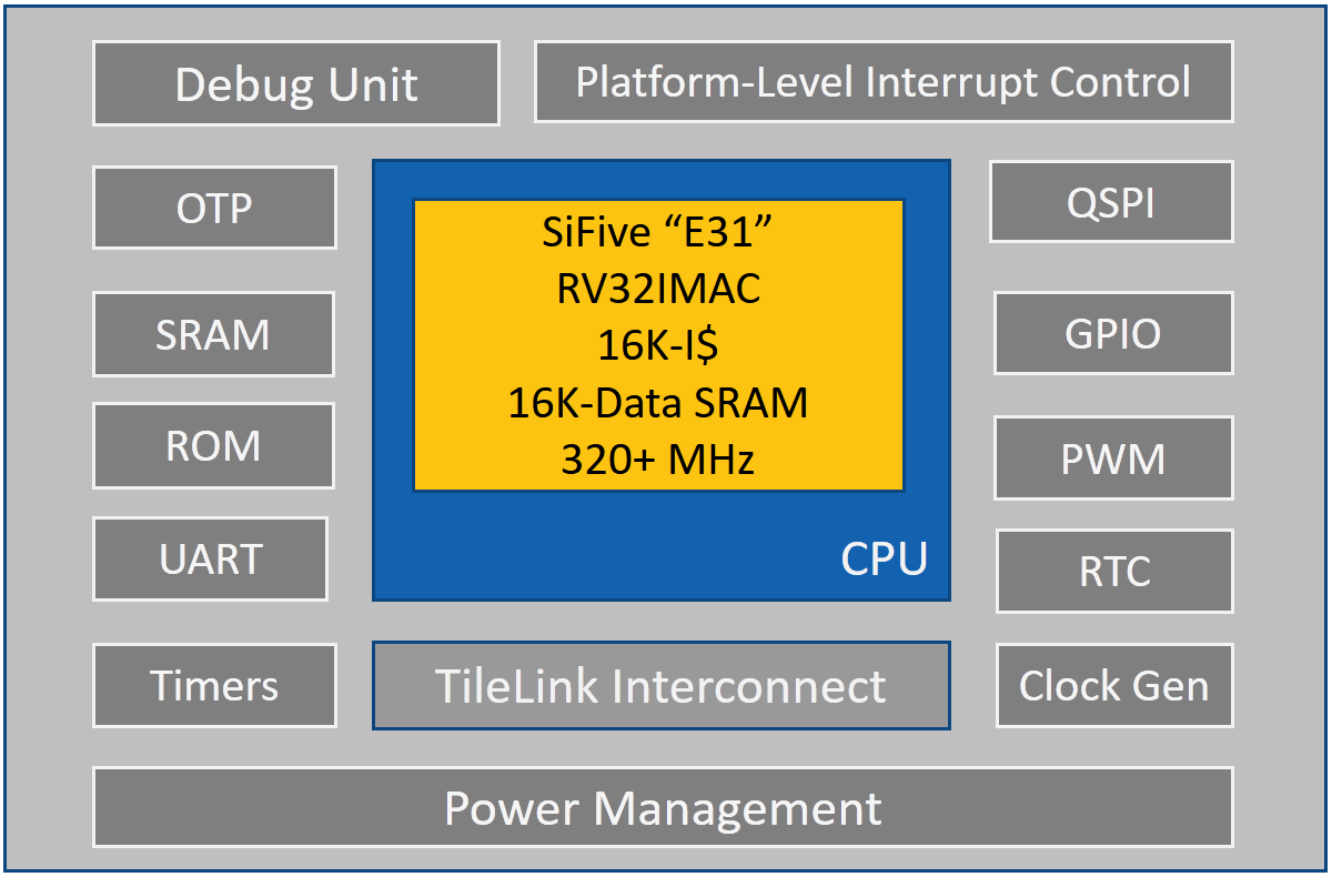
The Freedom E310 (FE310) is the first member of the Freedom Everywhere SoCs family, a series of customizable microcontroller SoC platforms, designed based on SiFive’s E31 CPU Coreplex CPU for microcontroller, embedded, IoT, and wearable applications. The SiFive’s E31 CPU Coreplex is a high-performance, 32-bit RV32IMAC core. Running at 320+ MHz.
FE310 Block Diagram
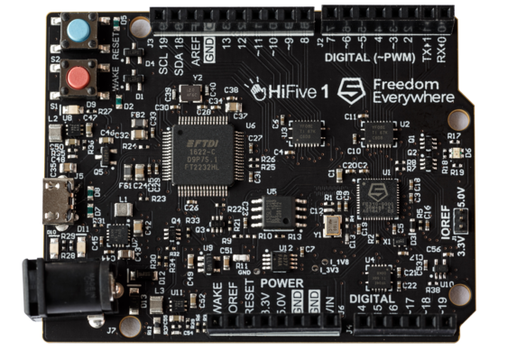
SiFive recently announced the ‘HiFive1’, an open-source Arduino-compatible RISC-V development board that features the FE310 SoC. It is a 68 x 51 mm board consists of 19 Digital I/O pins, 9 PWM pins, and 128 Mbit Off-Chip flash memory. HiFive1 operates at 3.3V and 1.8V and is fed with 5V via USB or with 7-12V DC jack. The board can be programed using Arduino IDE or Freedom E SDK.
HiFive1’s Specifications:
Microcontroller: SiFive Freedom E310 (FE310)
CPU: SiFive E31 CPU
Architecture: 32-bit RV32IMAC
Speed: 320+ MHz
Performance: 1.61 DMIPs/MHz, 2.73 Coremark/MHz
Memory: 16 KB Instruction Cache, 16 KB Data Scratchpad
Other Features: Hardware Multiply/Divide, Debug Module, Flexible Clock Generation with on-chip oscillators and PLLs
Operating Voltage: 3.3 V and 1.8 V
Input Voltage: 5 V USB or 7-12 VDC Jack
IO Voltages: Both 3.3 V or 5 V supported
Digital I/O Pins: 19
PWM Pins: 9
SPI Controllers/HW CS Pins: 1/3
External Interrupt Pins: 19
External Wakeup Pins: 1
Flash Memory: 128 Mbit Off-Chip (ISSI SPI Flash)
Host Interface (microUSB): Program, Debug, and Serial Communication
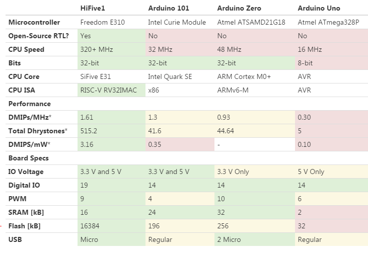
In a comparison with Arduino boards, the HiFive has 10x faster CPU clock, larger Flash memory, and lower power consumption. The table below shows the difference between Arduino UNO, Arduino Zero, and Arduino 101:
HiFive may be a helpful tool for system architects, hardware hackers and makers, to develop RISC-V applications, customize their own microcontroller, support open-source chips and open hardware. It is also good as a getting started kit to learn more about RISC-V.
You can order a HiFive board for $59 at its crowdfunding campaign, and the full documentation is available here.
Resistive random-access memory (RRAM or ReRAM) is a type of non-volatile (NV) random-access (RAM) computer memory that works by changing the resistance across a dielectric solid-state material often referred to as a memristor.
The MB85AS4MT is an SPI-interface ReRAM product that operates with a wide range of power supply voltage, from 1.65V to 3.6V. It features an extremely small average current in read operations of 0.2mA at a maximum operating frequency of 5MHz.
It is optimal for battery operated wearable devices and medical devices such as hearing aids, which require high density, low power consumption electronic components.
Main Specifications
Memory Density (configuration): 4 Mbit (512K words x 8 bits)
Write cycle time (256 byte page): 16ms (with 100% data inversion)
Data retention: 10 years (up to 85°C)
Package: 209 mil 8-pin SOP
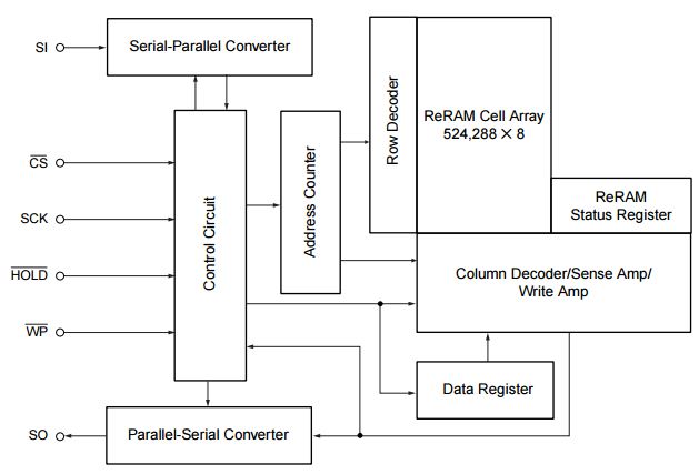
This figure shows the block diagram of the chip:
MB85AS4MT is suitable for lots of applications like medical devices, and IoT devices such as meters and sensors. In addition, the chip has the industry’s lowest power consumption for read operations in non-volatile memory.
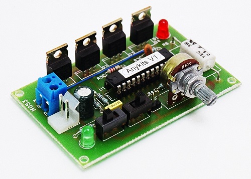
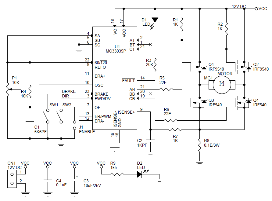
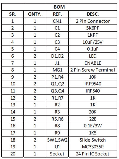
This is a 3AMP DC Motor speed and direction controller using MC33035 IC from on semiconductor, though the MC33035 was designed to control brushless DC motor , it may also be used to control DC brush type motors. MC33035 driving a Mosfets based H-Bridge affording minimal parts count to operate a brush type motor. On board potentiometer provided for speed control, slide switch for direction control and brake, On board jumper available to enable the chip. The controller function in normal manner with a PWM frequency of approximately 25Khz. Motor speed is controlled by adjusting the voltage presented to the non inverting input of the error amplifier establishing the PWM’s slice or reference level. Cycle by cycle current limiting of the motor is accomplished by sensing the voltage across the shunt resistor to the ground of H-bridge. The overcurrent sense circuit makes it possible to reverse the direction of the motor, using normal forward/reverse switch, on the fly and not have to completely stop it before reversing.
DC Motor & Direction Controller with Brake using MC33035 – [Link]
3AMP DC Motor speed and direction controller using MC33035 IC from on semiconductor, though the MC33035 was designed to control brushless DC motor , it may also be used to control DC brush type motors. MC33035 driving a Mosfets based H-Bridge affording minimal parts count to operate a brush type motor. On board potentiometer provided for speed control, slide switch for direction control and brake, On board jumper available to enable the chip. The controller function in normal manner with a PWM frequency of approximately 25Khz. Motor speed is controlled by adjusting the voltage presented to the non inverting input of the error amplifier establishing the PWM’s slice or reference level. Cycle by cycle current limiting of the motor is accomplished by sensing the voltage across the shunt resistor to the ground of H-bridge. The overcurrent sense circuit makes it possible to reverse the direction of the motor, using normal forward/reverse switch, on the fly and not have to completely stop it before reversing.
Specifications
SUPPLY 12-18V DC
Load Up to 3Amps, 5Amps with large size heat sink on Mosfets
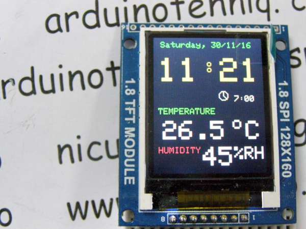
I use feature from article Another adjusting clock with alarm & thermometer using DS3231 on 1.8″ ST7735 display and change reading internal temperature of DS3231 with DHT22 sensor (AM2302), but you can use a cheaper and not very precise DHT11 sensor.
By using educ8stv_rtctft160_alarm_dht.ino or much better educ8stv_rtctft160_alarm_eeprom_dht.ino sketch, on display you can see: name of day, date, hour clock, hour alarm, temperature and humidity
Adjusting clock with alarm, hygrometer & thermometer on 1.8″ ST7735 display – [Link]
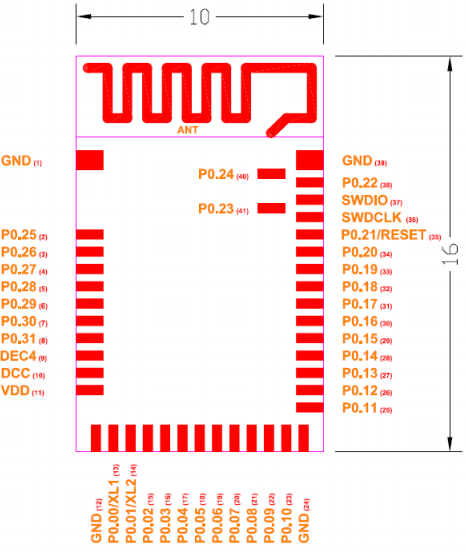
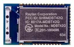
The open hardware innovation platform Seeedstudio produces the MDBT42Q, a Bluetooth Low Energy (BLE) module. It is a BT 4.0, BT 4.1 and BT 4.2 module designed based on Nordic nRF52832 SoC, a powerful, highly flexible ultra-low power multiprotocol SoC ideally suited for Bluetooth low energy, ANT and 2.4GHz ultra low-power wireless applications.
MDBT42Q features a dual transmission mode of BLE and 2.4 GHz RF with over 80 meters working distance in open space. It is a 16 x 10 x 2.2 mm board which contains GPIO, SPI, UART, I2C, I2S, PWM and ADC interfaces for connecting peripherals and sensors.
The nRF52832 SoC is built around a 32-bit ARM® Cortex™-M4F CPU with 512kB and 64kB RAM. The embedded 2.4GHz transceiver supports Bluetooth low energy, ANT and proprietary 2.4 GHz protocol stack. It is on air compatible with the nRF51 Series, nRF24L and nRF24AP Series products from Nordic Semiconductor.
MDBT42Q Specifications:
Multi-protocol 2.4GHz radio
32-bit ARM Cortex – M4F processor
512KB flash programmed memory and 64KB RAM
Software stacks available as downloads
Application development independent from protocol stack
On-air compatible with nRF51, nRF24AP and nRF24L series
Programmable output power from +4dBm to -20dBm
RAM mapped FIFOs using EasyDMA
Dynamic on-air payload length up to 256 bytes
Flexible and configurable 32 pin GPIO
Simple ON / OFF global power mode
Full set of digital interface all with Easy DMA including:
3 x Hardware SPI master ; 3 x Hardware SPI slave
2 x two-wire master ; 2 x two-wire slave
1 x UART (CTS / RTS)
PDM for digital microphone
I2S for audio
12-bit / 200KSPS ADC
128-bit AES ECB / CCM / AAR co-processor
Lowe cost external crystal 32MHz ± 40ppm for Bluetooth ; ± 50ppm for ANT Plus
Lowe power 32MHz crystal and RC oscillators
Wide supply voltage range 1.7V to 3.6V
On-chip DC/DC buck converter
Individual power management for all peripherals
Timer counter
3 x 24-bit RTC
NFC-A tag interface for OOB pairing
RoHS and REACH compliant
This BLE module can be used in a wide range of applications, such as Internet of Things (IoT), Personal Area Networks, Interactive entertainment devices, Beacons, A4WP wireless chargers and devices, Remote control toys, and computer peripherals and I/O devices.
Full specifications, datasheet, and product documents are available at seeedstudio store, it can be backordered for only $10.


 The
The