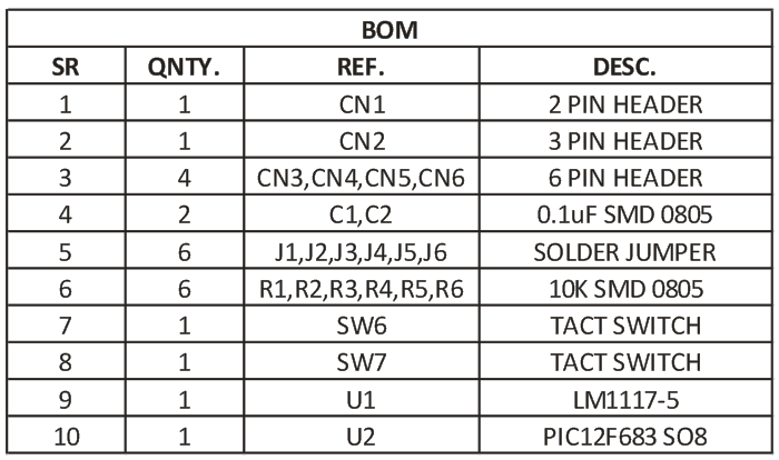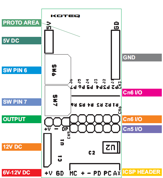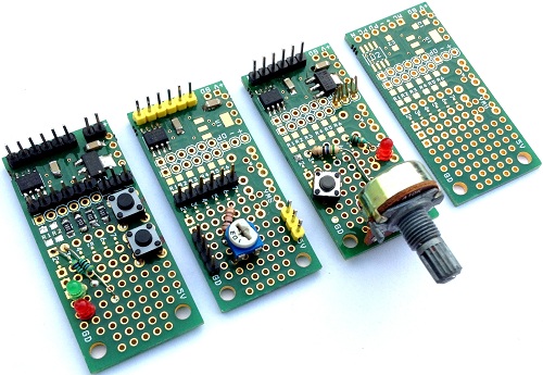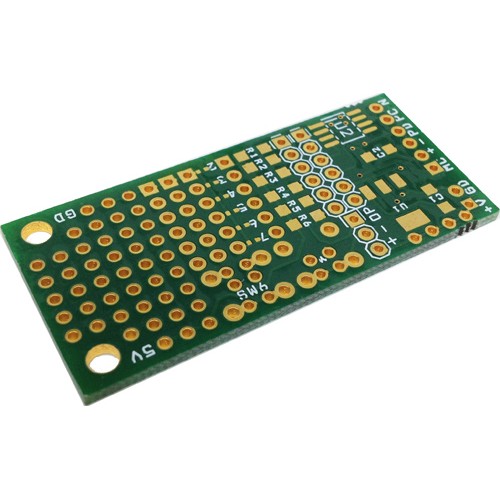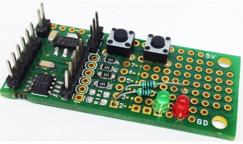
8 PIN SMD PIC development board is a full-featured development board and platform for 8-bit PIC® microcontrollers. This project is a versatile development solution, featuring several options for external sensors, off-board communication and human interface. Additionally, it offers ample room for expansion, making it an excellent solution for developers and engineers looking for a PIC development board. The 8 Pin SO8-SMD PIC Development / Evaluations Board demonstrates the capabilities of Microchip’s 8-bit microcontrollers, specifically, It can be used as a standalone demonstration board with a programmed part. With this board you can develop and prototype with all Microchip’s 8 PIN PIC microcontrollers which doesn’t required crystals (External Oscillator). On board connector for ICSP allows an easy programming. The board has configurable pull ups on all pins can be soldered or abandon as per requirement, All pins has solder Jumpers for pull down. Onboard 5V regulator, two tact switch, one output connector to interface with 12V Relay board or solid state AC or DC Relay. Board has small prototype area. We have considered PIC12F683 IC for this Board.
8 PIN PIC Development Board – PIC12F683 – [Link]