Badgerboard, LoRa Future IoT Development Board

The LoRa Alliance™ is an open, non-profit association of members who believe that the Internet of Things era is now, its LoRaWAN is a Low Power Wide Area Network with features that support low-cost, mobile, and secure bidirectional communication for Internet of Things (IoT), machine-to-machine (M2M), smart city, and industrial applications. LoRaWAN is optimized for low power consumption and is designed to support large networks with millions and millions of devices. Innovative features of LoRaWAN include support for redundant operation, geolocation, low-cost, and low-power – devices can even run on energy harvesting technologies enabling the mobility and ease of use of Internet of Things.

Check this video to learn more about LoRa and its protocol:

Badgerboard is an Arduino compatible LoRaWAN™ open source development kit, that can be easily extended to a prototype or even a small batch product. Development board has a battery charger and antenna connector on board.

Using as small as the battery you have in your watch, you can power your Badgerboard to send and receive radio waves, that can reach from 1km to 3km in the urban area up to 10+ km in the rural areas

94e86e7d258145170df83e310866865b_original

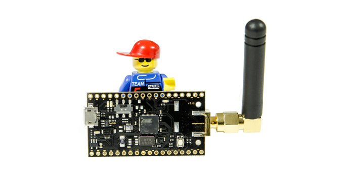
The communication is powered by widely used Microchip LoRaWAN module. There are two editions of the module one using  RN2483-I/RM101 for the 433/868 frequency bands and the other is using RN2903-I/RM095 for the 915 MHz band and its sub-bands. The LoRaWAN stack is already part of the module and all needed libraries for LoRa functionality are included.

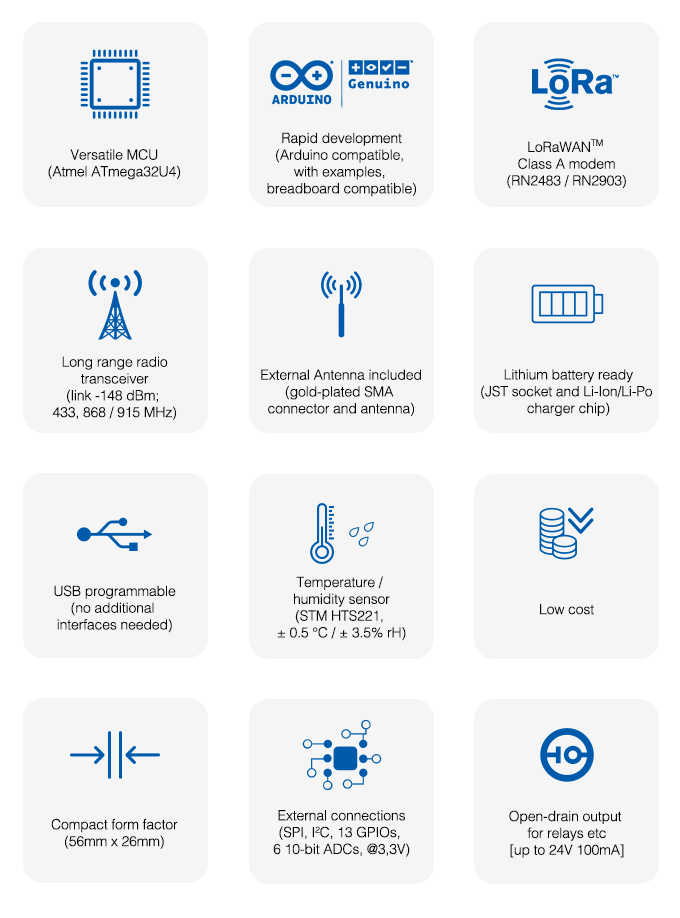
Here are the features of the module:

306d6b0953444211c0519770c96c47da_original

Check Badgerboard in action and the possibilities that can be done using it:

https://www.youtube.com/watch?v=4ue3iAwNgNE

Badgerboard is now live on a Kickstarter campaign, you can pre-order the early bird board for $45 here. You can check their website to keep involved with the latest updates www.badgerboard.io

4 Channel Relay Board

4-channel-relay-board-i044-500x500

4 Channel Relay Board is a simple and convenient way to interface 4 relays for switching application in your project. Very compact design that can fit in small area, mainly this board is made for low voltage applications.

Features

  • Input supply 12 VDC @ 170 mA
  • Output four SPDT relay
  • Relay specification  10A/24V DC
  • Trigger level 2 ~ 5 VDC
  • Header Connector for connecting power and trigger voltage
  • LED on each channel indicates relay status
  • Power Battery Terminal (PBT) for easy relay output and aux power connection
  • Four mounting holes of 3.2 mm each

Applications: Robotics, Electronics projects, Industrial controls, Microwaves Oven, Fans, DC Motor, AC Lamp, Solenoids Remote Controls etc.

Note: The board is designed for low voltage switching application, maximum supply at relay contacts 48V DC/7Amps

Schematic

4-channel-relay-board-sch

Parts List

4-channel-relay-board-bom

Photos

4-channel-relay-board-img_0048

LC-04 4 Channel Logic Converter 3.3V – 5.0V

If you have ever tried to connect a 3.3V device to a 5V system, you know what a challenge it can be. The LC-04 bi-directional logic level converter is a small device that safely steps down 5V signal to 3.3V and steps up 3.3V to 5V at the same time. In this instructable, mybotic explained the procedure to use the LC-04 bi-directional logic converter.

Description:

The LC-04 module offers bi-directional shifting of logic level for up to four channels. The logic level HIGH (logic 1) on each side of the board is achieved by 10K Ω pull-up resistors connected to the respective power supply. This provides a quick enough rise time of logic level to convert high frequency (400KHz I²C, SPI, UART etc.) signals without delay.

This module has the following features:

  • Dual-supply bus translation :
    • Lower-voltage (LV) supply can be 1.5 V to 7 V
    • Higher-voltage (HV) supply can be LV to 18 V
  • Four bi-directional channels
  • Small size: 0.4″ × 0.5″ × 0.08″ (13 mm × 10 mm × 2 mm)
  • Breadboard-compatible pin spacing
    The bi-directional level-shifting circuit
    The bi-directional level shifting circuit

The Pinout:

The LC-04 logic level converter has two types of pins:

  1. Voltage input pins :
    • 2 pins (GND and LV) on Low Voltage  side
    • 2 pins (GND and HV) on High Voltage  side
  2. Data channels :
    • 4 pins (LV1, LV2, LV3, and LV4) on Low Voltage  side
    • 4 pins (HV1, HV2, HV3, and HV4) on High Voltage  side

Pin HV and LV set HIGH (logic 1) logic level on High voltage side and Low voltage side respectively, with respect to the GND.

Data channel pins shift logic levels from one voltage reference to another. A low voltage signal sent into LV1, for example, will be shifted up to the higher voltage and sent out through HV1. Similarly, a high voltage signal sent into HV1 will be shifted down to the lower voltage and sent out through LV1.

LC-04 Bi-directional logic level converter pinout

Parts List:

  1.  LC-04 4 Channel Logic Level Converter
  2. Arduino Uno Board and USB Cable
  3. Breadboard
  4. Crocodile Clip (optional)
  5. Multimeter

The Wiring:

The wiring is pretty simple. You may even omit the breadboard by making end-to-end connections. Two types of connections are required:

  1. Pin connection to shift down (5V to 3.3V)
  2. Pin connection to shift up (3.3V to 5V)
Pin Connection to Shift Down:
  1. LV to 3.3V
  2. LV’s GND to multimeter’s black probe
  3. LV3 to multimeter’s red probe
  4. HV to 5V
  5. GND to UNO’s GND
  6. HV3 to Digital Pin 4
Logic level shift down using LC-04 logic level converter
Logic level shifting down using LC-04 logic level converter
Pin Connection to Shift Up:
  1. LV to 3.3V
  2. LV’s GND to UNO’s GND
  3. LV3 to Digital Pin 4
  4. HV to 5V
  5. GND to multimeter’s black probe
  6. HV3 to multimeter’s red probe
Logic level shifting up using LC-04 logic level converter

Introducing Autodesk Circuits Simulator For Beginner

Circuits.io is an online platform created by Autodesk for hardware hackers. It provides a browser-based application for designing, simulating electronic circuits and creating PCB boards. Autodesk circuits simulator can simulate Arduino-based projects for testing designs and programs before creating them in real life.

tumblr_inline_myzj7r9yiv1qal3cc

The simulator allows you to learn electronics using a virtual Arduino board and breadboard without blowing up capacitors or burning yourself with solder on your work table. It is free to use, but more features are available with premium accounts. To start using circuits.io just go to the website, create an account, and start building your circuit.

This instructable guides you to get familiar using the simulator through three different projects. You will only need a computer with internet access, and you can build these projects in real if you have the components.

In this tutorial you will work with these parts:

  • Arduino Board, the brain of your circuits.
  • Breadboard, the board where you will connect the elements.
  • Breadboard wires.
  • Resistors.
  • LEDs.
  • Potentiometer.
  • LCD.
  • DC motor.

The first project is simple and easy, it is about making a LED turn on and off continuously. The circuit consists of only one resistor and one LED connected with the Arduino, which will turn the LED on and off for a period of time defined in the code.

blink

Another simple project is based on the LCD (Liquid Crystal Display) which receives information from Arduino and displays it. You can program the Arduino to display a message you want, control its location, make it blink, or move the message on the screen. You will also use a resistor and a potentiometer to control the brightness of the backlight.

lcd

In the third project you will control DC motor speed and its spins in Autodesk Circuits. The motor must be fed by an external power source, and the Arduino will control the current flow to the motor through the TIP120 transistor.

motor

The full instructions and guides are available in this instructable. When you finish making these projects you can explore the simulator features and components, and start building your own projects.

Using a Color Sensor (TCS230) with Arduino Uno and ST7735 color TFT display

In this video tutorial educ8s.tv show us how use the TCS230 color sensor with Arduino:

Hey guys, I am Nick and welcome to educ8s.tv a channel that is all about DIY electronics projects with Arduino, Raspberry Pi, ESP8266 and other popular boards. In this video we are going to learn how to use the TCS230 color sensor, a very interesting sensor. I have built a simple project to demonstrate that this sensor is really capable. I use an Arduino Uno and a 1.8” Color TFT display and of course the color sensor. As you can see, the sensor detects the colors and it displays them on the screen. The color we get on the screen is pretty close to the real color of the object. Cool isn’t it? Now, let’s see the parts that we need in order to build this project.

Using a Color Sensor (TCS230) with Arduino Uno and ST7735 color TFT display [Link]

2.7V-4.2V input to 3.3V – 0.6A output Buck-Boost Converter using LTC3440

This project shows a DC-DC buck boost circuit which can produce an output of 3.3V for an input of 2.7V to 4.2V , for example from a Li-on battery. The Circuit uses LTC3440 Buck boost IC which is a fixed frequency boost converter. To get high efficient results, inductor with high frequency core material should be used.

Features

  • Input(V): 2.7V DC to 4.2V DC
  • Output(V): 3.3V DC
  • Output load: 600mA
  • PCB:23mmX15mm


Parts List

Large Current Relay with Dual Output DC-DC Converter for Hobby CNC/Router

Single Channel Large current relay board with dual DC-DC converter board is mainly designed for Hobby CNC, Routers, and Plasma cutters.

Hobby CNC controller requires multiple DC outputs to drive various things.  This board provides 5V DC and 12V DC 1Amp each. The dual supply helps driving LPT breakout board, Sensors, Limit switches and few other things that require 5V and 12V.

The Relay has large current handle capacity and can be used to drive spindles, solenoids, and other things that require switching. The relay requires TTL High signal to trigger or it has the capability to even trigger with GND signal.

Features

  • Supply Input 15V to 35V DC
  • DC Outputs 5V @ 1A & 12V 1A
  • On Board LED for Relay Output
  • Relay Contact 20Amp NC and 30 Amps No 230V AC
  • Relay Trigger 5V TTL in or GND input
  • Screw Terminal and 2 Pin Header Connector Provided for Supply Input
  • Screw Terminal and 2 pin header provided for 5V DC & 12V DC Output
  • 3 Pin Screw Terminal Provide for Relay output Connections NO/NC
  • 3 Pin Header Connector for TTL + Signal Trigger, and Low GND signal Trigger
  • Close The Jumper to trigger rely with low GND signal input

Schematic

large-current-relay-schematic

Parts List

large-current-relay-bom

Photos

large-current-relay-img_0040

large-current-relay-m119-500x500

Keeping up with Moore’s Law

20160816100854_toshiba-memorys

by Clemens Valens @ elektormagazine.com:

There was a time that every extra storage byte crammed into a chip was greeted with cheers and applause but today only few people will get the champagne out when an extra gigabyte or so is announced. We have become so used to the ever growing capacity of memory chips that new product launches in this area do not create much excitement anymore. Yet sometimes an event manages to stir things up a bit, like a few weeks ago when a major semiconductor manufacturer announced that it started sampling its new 32 gigabyte flash memory chip.

Keeping up with Moore’s Law – [Link]

Load switch with self-resetting circuit breaker

di5467f1

has designed a simple load switch using two transistors and some resistors.

The simple current-limiting load switch shown in Figure 1 will be familiar to most readers. In this circuit, a high level signal applied to the input switches on MOSFET Q2, which energizes the load. The load current is limited by negative feedback applied via Q1.

Load switch with self-resetting circuit breaker – [Link]

LT8630 – 100V, 600 mA synchronous buck DC/DC betters 93% efficiency

161121edne-linear8630
LT8630 is a 600 mA, 100V input capable synchronous step-down switching regulator using synchronous rectification to deliver efficiency as high as 93% while Burst Mode operation keeps quiescent current under 7 µA in no-load standby conditions. by By Graham Prophet @ edn-europe.com:

The device’s 3V to 100V input voltage range suits it for 48V automotive systems, dual battery transportation, industrial and 36V to 72V telecom applications. Its internal high efficiency switches can deliver up to 600 mA of continuous output current to voltages as low as 0.8V.

LT8630 – 100V, 600 mA synchronous buck DC/DC betters 93% efficiency – [Link]

TOP PCB Companies