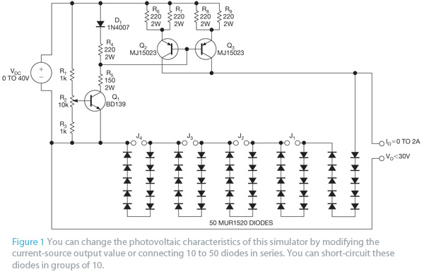
Electronics engineers often use photovoltaic-module simulators to test dc/dc-power converters, inverters, or MPPT (maximum-power-point-tracking)-control techniques. The use of these simulators lets you work in the laboratory with predefined photovoltaic conditions, thus avoiding the drawbacks of real photovoltaic modules. Various commercial simulators are available, but they are often expensive.
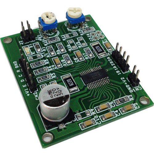
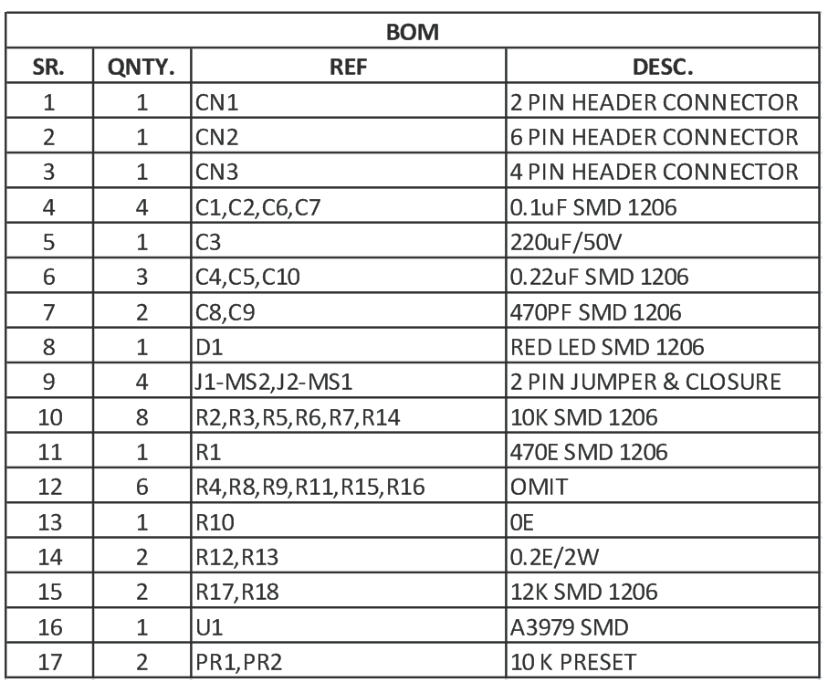
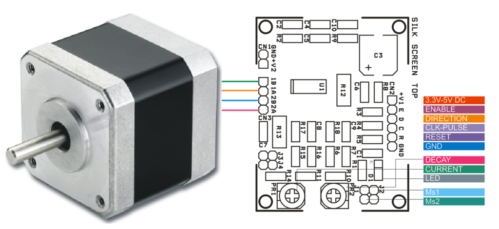
The tiny board designed using A3979 IC from ALLEGRO which is complete micro stepping driver with built in translator. The translator is the key to the easy implementation of the A3979. It allows the simple input of one pulse on the STEP pin to drive the motor one micro step, which can be either a full step, half, quarter, or sixteenth, depending on the setting of the MS1 and MS2 logic inputs. There are no phase-sequence tables, high-frequency control lines, or complex interfaces to program. The A3979 interface is an ideal fit for applications where a complex microprocessor is unavailable or is overburdened.
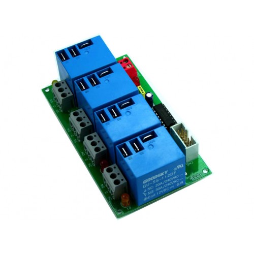
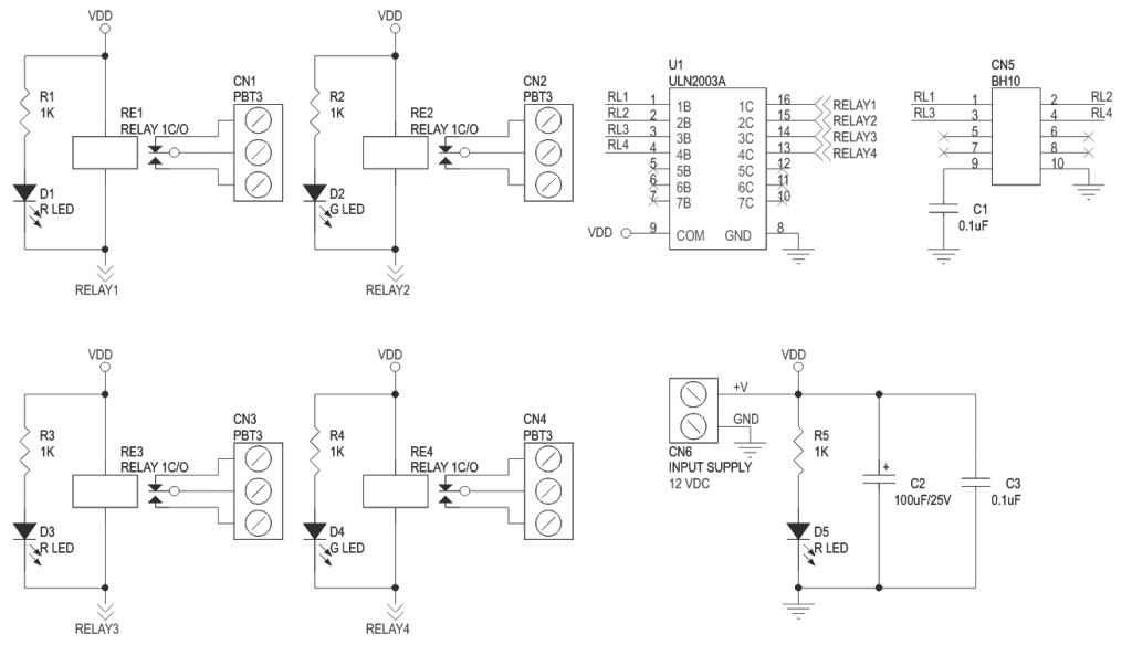
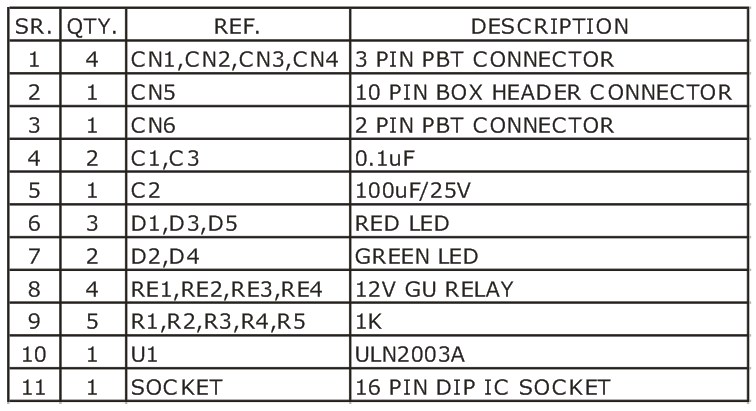
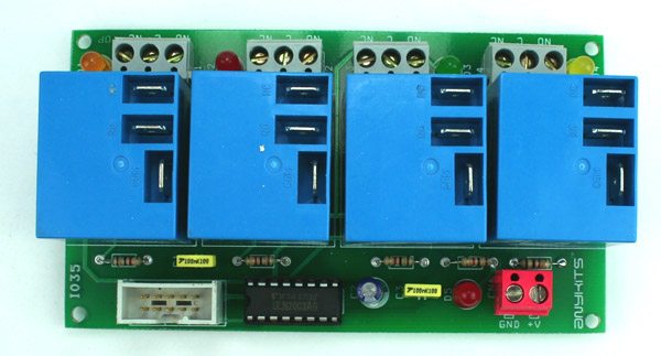
4-Channel Relay Board is a simple and convenient way to interface 4 relays for switching application in your project. The project has large Relay which can switch current up to 20Amps.
Specifications
Input supply 12 VDC @ 360 mA
Output four SPDT Relay
Relay specification 20 A @ 230 VAC NC/30A NO
Trigger level 2 ~ 5 VDC
Box Header connector for connection of trigger signal
LED on each channel indicates relay status
Power-On LED indicator
Screw terminal connector for easy relay output and power in connection
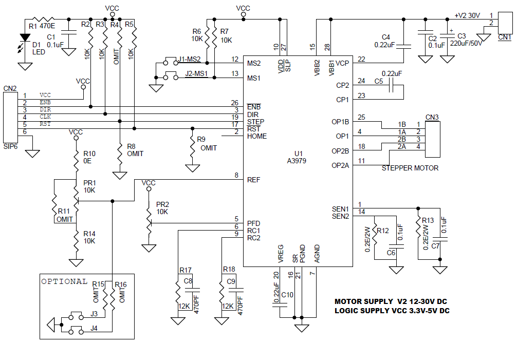
The tiny board designed using A3979 IC from ALLEGRO which is complete micro stepping driver with built in translator. The translator is the key to the easy implementation of the A3979. It allows the simple input of one pulse on the STEP pin to drive the motor one micro step, which can be either a full step, half, quarter, or sixteenth, depending on the setting of the MS1 and MS2 logic inputs. There are no phase-sequence tables, high-frequency control lines, or complex interfaces to program. The A3979 interface is an ideal fit for applications where a complex microprocessor is unavailable or is overburdened.
J3, J4 Option Replacement for PR1 Jumper Type Current Setting
D1 Logic Power LED
REF (PR1) Current Adjust 0-2V
PFD (PR2)
When A step input signal commands a lower output current then the previous step, it switches the output current decay to either slow, fast or mixed decay mode, depending on the voltage level at the PFD input. If the voltage at PFD input is greater than 0.6xVCC, then slow decay mode selected, if the voltage on PFD input is less than 0.21xVCC then the fast decay mode selected, when VPFD is between these two levels mixed decay mode selected.
4-Channel Relay Board is a simple and convenient way to interface 4 relays for switching application in your project. The project has large Relay which can switch current up to 20Amps.
Specifications
Input supply 12 VDC @ 360 mA
Output four SPDT Relay
Relay specification 20 A @ 230 VAC NC/30A NO
Trigger level 2 ~ 5 VDC
Box Header connector for connection of trigger signal
LED on each channel indicates relay status
Power-On LED indicator
Screw terminal connector for easy relay output and power in connection
A new tutorial by The DIY Life is for building a home energy meter that provides information about power consumption and cost estimates for the month.
Using Arduino and some other components you can build your own energy meter that measure the supply current to your home through a CT (current transformer), current, power, maximum power and kilowatt hours consumed. The cost of electricity used to date can be added and displayed easily.
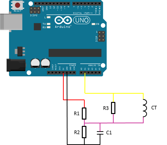
First you have to build the current sensor by connecting the CT to the Arduino and setting a right voltage reference due to the Arduino 0-5V input range. As shown below, this is the way you should connect the CT to the Arduino.
This code should be uploaded to your Arduino to run the project. It already has a scaling factor that can be adjusted due to the components you choose in your circuit.If you don’t want to use or don’t have an LCD screen, you can also modify the sketch to output to the Arduino IDE’s serial window as described in this code.
For more information on how to choose different components, how to calibrate them, and to learn more details about wiring and coding, you should check this tutorial out.
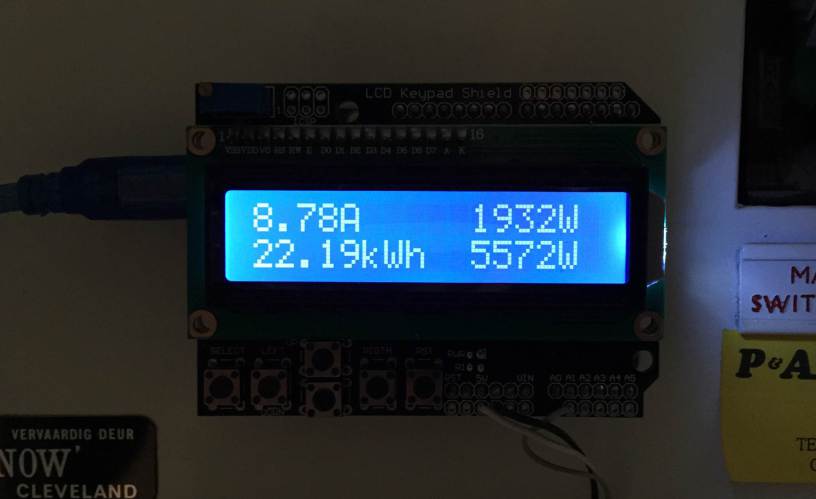
The first number displayed is the instantaneous current followed by the instantaneous power. On the bottom line, the kilowatt hours used since reset and then the maximum recorded power since reset. Check the meter in action:
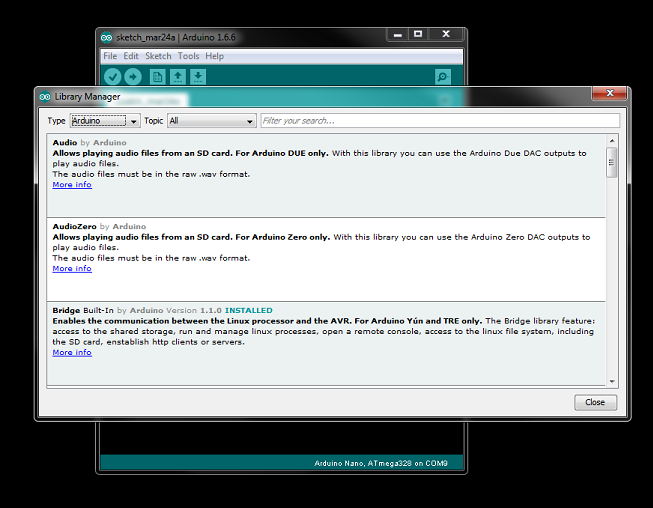
runtimeprojects.com has a tutorial on how to install and use Arduino libraries.
Libraries are an essential part in the Arduino world. They are what makes Arduino so easy to use. Libraries are written to encapsulate complex functions and expose them as simple function calls to the user. For example to switch a pixel on and off in an LED monitor. This is relatively very complex but, fortunately some folks at Adafruit created a library that enables us to handle an LEd monitor with simple functions like, draw lines, text, circles, rectangles, etc… Normally these libraries include a readme file with some explanations about the various functions, and examples of how to use the library.
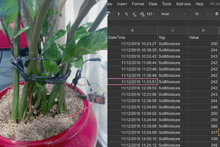
Although there are so many cloud IoT platforms (ThingSpeak, thinger.io, TESPA.io, Xively, … ) available in the market, each offering APIs and tools to allow the Arduino and ESP8266 users to directly upload their sensor readings online for real-time visualization and global access, Google Drive is still my favorite choice for posting sensor data online as it is more approachable. If you are a regular user of Google Drive, you would find this tutorial from Anir very useful too. It describes a method of connecting the ESP8266 device directly to a Google sheet for storing the sensor data without using any third party service, like pushingbox that most other Arduino users have used for fulfilling Google’s http requirements and handling the URL redirection. This tutorial explains how you can make the task much simpler by using a recently published HTTPSRedirect Arduino library by Sujay Phadke that allows the ESP8266 to self-handle the redirect and https GET requests. The tutorial uses a NodeMCU board and a soil moisture sensor as input for demonstration. The sensor data are directly posted to a spreadsheet on Google Drive.
ESP8266 connecting to Google spreadsheets for data logging
The way it works is you need to setup a Google Apps Script to access a spreadsheet in your Google Drive. The script have access to the spreadsheet via its document sharing key, which is unique and can be found on the URL of the sheet. In order to remotely run the Google Script without exposing your Google credentials, you need to publish it as a Web App URL. The ESP8266 can then send data to the spreadsheet using the same Web App URL with actual sensor data appended to it. Because Google requires you to send any GET request over an Web App URL using https (more secured than http), and then redirect your request to another URL location, the HTTPSRedirect Arduino library by Sujay Phadke is the key to handle this smoothly. Otherwise, you would need to use a third party online service to accomplish the same. The tutorial also describes how to configure the Google spreadsheet for receiving the soil moisture data in correct cells and uses some built-in chart features to display the time series in real time.
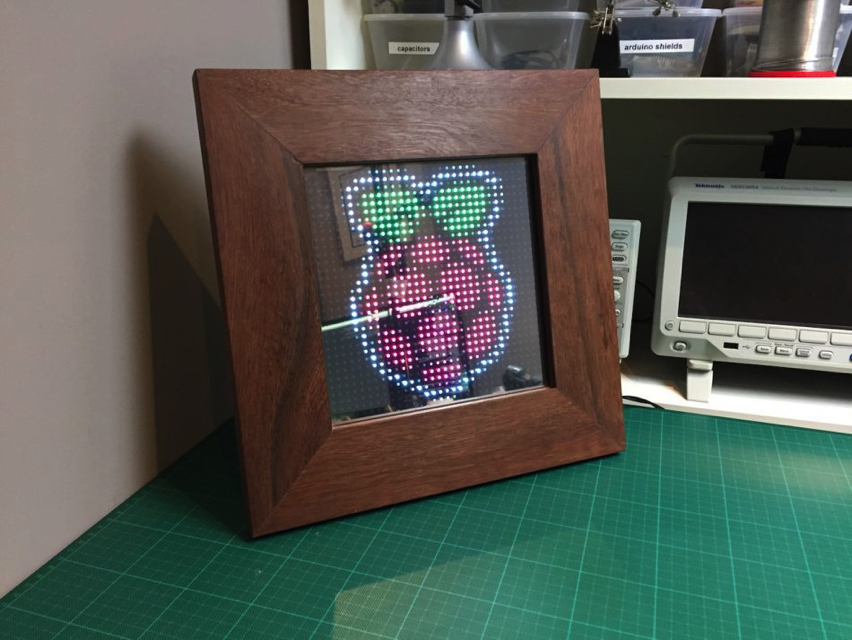
Have you ever wanted to get an interesting art frame? That can display and flip photos, scroll text, show the weather or display social media notifications?
Frederick Vandenbosch’s new tutorial is for building an art frame using 32×32 LED matrix and Raspberry Pi Zero.
You can watch a detailed step-by-step tutorial for assembling the frame in this video:
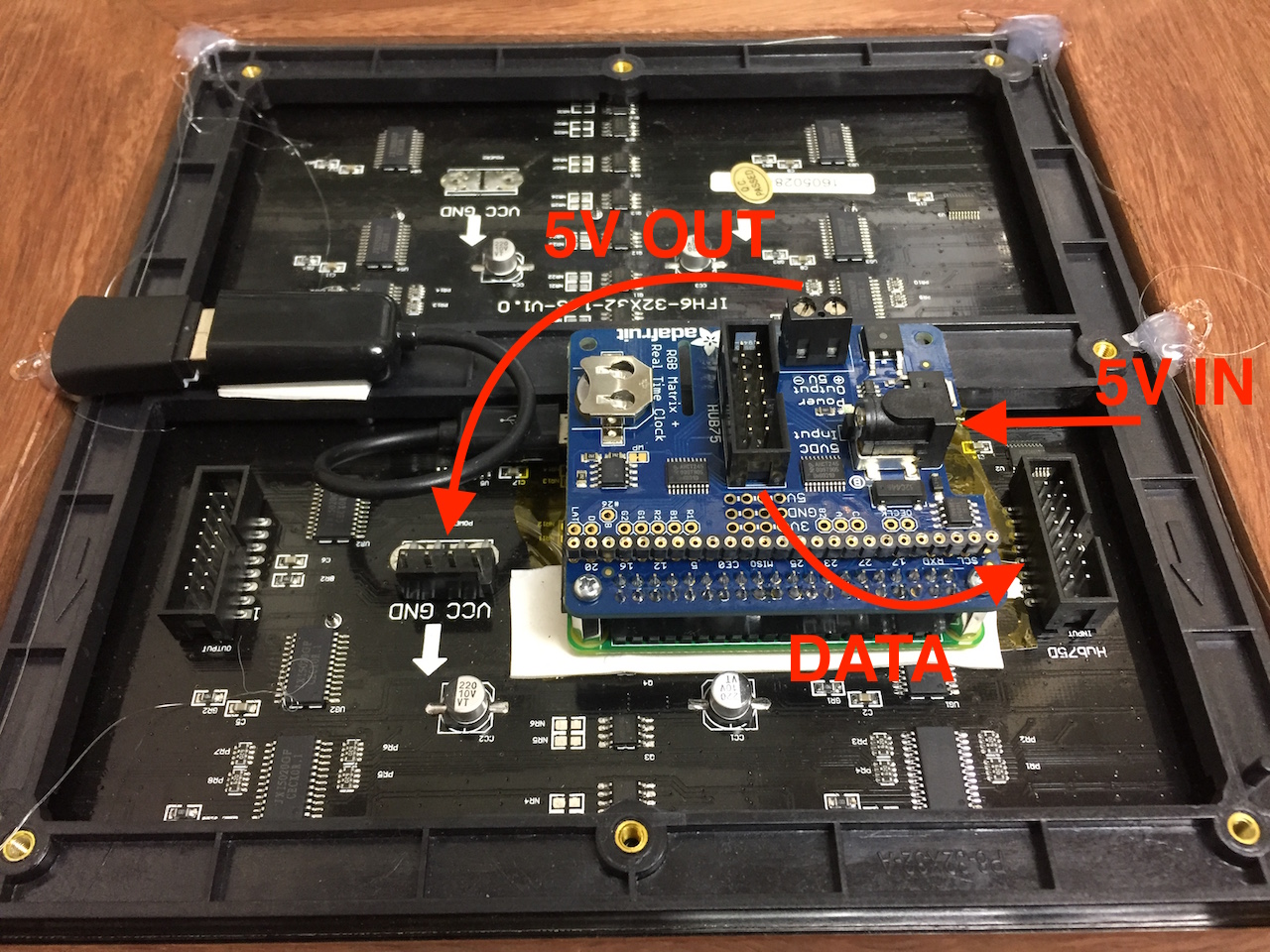
You can use the Adafruit RGB Matrix HAT like the tutorial to control the matrix and to make wiring simpler. But it is not mandatory, you can also wire the LED matrix directly to Pi’s GPIO. A USB Wifi adapter or dongle plugs into one of your desktop or laptop’s USB ports, allowing you to connect to a wireless network in the home, office, or a public place. You can use this connection to access shared files, devices, and documents, or to connect to the Internet. To connect this dongle with your Pi Zero you need a OTG USB cable. Connecting this dongle with your projects will open up for you doors of innovation, and that what made this frame cool!
The wiring is as described in this picture.
Frederick used Raspbian Jessie “lite edition” for his Zero since the application is time-critical. Because it has more improvements, he preferred using Henner Zeller’s rpi-rgb-led-matrix library instead of the regular Adafruit library – which lately seemed an old version of the same series. He wrote a code to display and scroll ppm images, you can check it out here.
You can also use Raspberry Pi 3 in order to build this project, no need to change anything in software, and no need for the Wifi dongle since you can use the onboard Wifi. Things can be displayed on the matrix are unlimited. Since you have it connected with internet, this project could be your next IoT hack!
With a local (on chip) precision of ±1°C over a range of temperature from –40°C to +65°C, and a remote (up to 3 external sensors) precision of ±1°C extended up to +125°C, the MCP990X digital temperature sensor offers an economic and flexible solution for external of industrial environments.