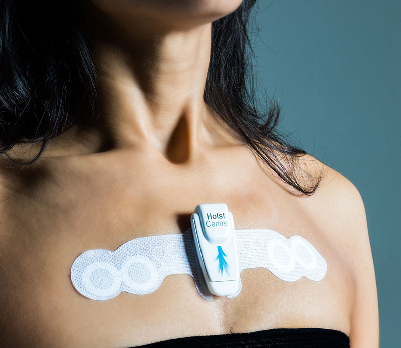
Belgian Imec and its subsidiary Holst Centre have developed a health patch which tracks physical and cardiac activity while monitoring bioelectrical impedance. The technology is up for licensing. by Jan Buiting @ elektormagazine.com
The health industry has recognized the challenges and solutions, with analysts predicting that the value of the global mobile health market is expected to more than triple in the next few years, from $19.2 billion in 2016 to $58.8 billion by 2020.
A health patch a day keeps the doctor away – [Link]
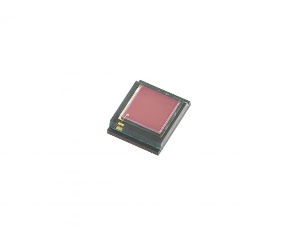
Everlight (New Taipei City, Taiwan) has introduced an ambient light sensor that operates at 550nm with a very low signal calculation failure rate and a high current efficiency. An anticipated application for this device is heart rate signal detection in wearable electronics for the health and fitness sector. by Graham Prophet @ edn-europe.com:
Based on the principle of PPG (photoplethysmogram), the heart rate signal is calculated according to the current changes in transmission and reflection between a green light LED and the sensor to detect the systolic and diastolic blood vessel rythym. With a large detection area of 8.1mm ², improved signal strength is available from the ALS-PD50-42C. The larger sensing area can also improve the capabilities in instances when there are signal interferences caused by people’s skin colour, tattoos and hair on the skin.
Ambient light sensor for heart rate sensing in wearables – [Link]
Researchers at Stanford University have just invented a revolutionary way of communication. They are replacing the conventional way of wiring, wireless, radio and Bluetooth connectivity using chemicals that can be found in every house.
Nariman Farsad, now a postdoctoral fellow at Stanford, had built the first ever experimental chemical texting system in York University, which used vodka to send its messages.
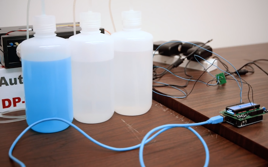
While making research in the lab of Andrea Goldsmith, professor of electrical engineering, he and his fellow researchers have built a machine that sends messages using common chemicals. With the use of vinegar and glass cleaner, Farsad overcomes some hurdles he faced while sending data using vodka. In his vodka messaging machine, the signal would build up to the point that the receiving end was too saturated with vodka to receive more messages. Instead, easy to obtain chemicals like vinegar and glass cleaner could do better and plus these two specific liquids can cancel each other out at the receiving end of the system.
This system is extracting one and zero bits out of liquid since it sends pulses of acid (vinegar) or base (glass cleaner). After typing the message in a small computer, it will be send to a machine that pumps out the corresponding “bits” of chemicals, which travel through plastic tubes to a small container with a pH sensor. Changes in pH are then transmitted to a computer that deciphers the encoded message.
While working in Wireless Systems Laboratory, Goldsmith had faced a lot of challenges in her career in wireless communication and worked hard to overcome them, but now dealing with chemicals will be a new adventure for her and her research group without any previous best practices.
“Every problem that we’ve addressed in traditional wireless communications over the last three or four decades is really different now because it’s a different mode of communicating,” Goldsmith said. “As so, it opens up all of these new ways of thinking about the optimal way to design this type of communication system.”
Most of nanotechnology solutions that are out there are small in size, need power plus some wiring for connectivity, or depend on high frequency signals to operate, what would be harmful for body functions. This new chemical technology can be widely used in body-related sensors since chemical-based data exchange could be self-powered, traveling throughout the body harmlessly and can not be detected by outside devices.
Goldsmith and Farsad are now working in two directions, improving the current chemical texting system, and collaborating with two bioengineering groups at Stanford to make human body-friendly chemical messaging a reality.
This technology can open up new avenues in communication protocols replacing the base unit, the electricity, with chemicals.
You can read more about this brand-new way of communication at Stanford University website, and you can learn more in this video
The voice unit (VU) meter is a device that displays a representation of the signal level in audio equipment. It is used in some consumer audio equipment for utilitarian purposes such as in recording devices or for aesthetics like playback devices.
The original VU meter is a passive electromechanical device, but using a few LEDs with a controller and some lines of code, you will be able to make an interesting digital VU meter device.
These two instructables (1, 2) present an easy way to build a VU meter using an Arduino. In the first one the sound signals are received from an audio jack connected with a mobile phone or MP3 player, and the output is displayed on a 10-LED row. The second is an enhanced version of the meter, the signals will be collected via a microphone, and the LEDs row is replaced with a LED logo to visualize the VU meter output.
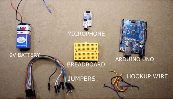
Components required for both versions are:
Breadboard
Microphone module
Arduino Uno
3mm LEDs
100ohm Resistor
Battery – 9V
Hookup wires and jumpers
RCA cable
Veroboard and soldering equipment are required if you want to make your own LED design.
First, design your LED logo by sorting the LEDs on the veroboard. You can use VeroDes to simplify this, it is an easy-to-use design program for those wishing to design circuits on veroboard. Make your design, print it, and then do some soldering.
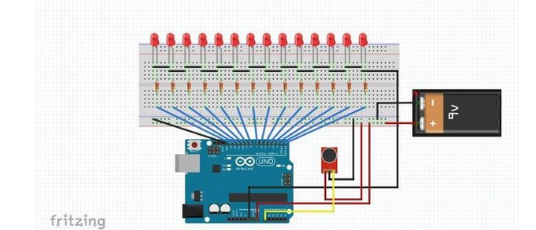
Connect the LEDs with the digital pins from 2 to 13 with the 100 ohm resistors, and each resistor should be connected with a LED row. The digital pins will act as a positive voltage to the LEDs. Finally connect the microphone or the audio cable with the A0 pin as shown in the figure.
Now upload this Arduino sketch, power on the circuit, play music and enjoy the show. You may need to adjust the gain in microphone module to get the perfect result.
Atmel tinyAVRmicrocontrollers are optimized for applications that require performance, power efficiency and ease of use in a small package. All tinyAVR devices are based on the same architecture with other AVR devices. The integrated ADC, DAC, EEPROM memory and brown-out detector let you build applications without adding external components. The tinyAVR also offers Flash Memory for fast, secure and cost-effective in-circuit upgrades that significantly cuts your time to market.
The latest tinyAVR devices (ATtiny417/814/816/817) by Atmel combine AVR core with CIPs (Core Independent Peripherals). PIC microcontrollers with Core Independent Peripherals (CIPs) already raised the performance of 8-Bit-MCUs to a new level. Since the acquisition of Atmel by Microchip, this is the first time the company leverages features from both MCU families.
So, now the question is:
What Is CIP?
In fact, the term CIP or Core Independent Peripherals is pretty much self-explanatory. Microchip’s description of CIP is:
CIPs allow the peripherals to operate independently of the core, including serial communication and analog peripherals. Together with the Event System, that allows peripherals to communicate without using the CPU, applications can be optimized at a system level. This lowers power consumption and increases throughput and system reliability.
Core Independent Peripherals or CIPs are designed to handle their tasks with no code or supervision from the CPU to maintain their operations. As a result, they simplify the implementation of complex logic control systems and give designers the flexibility to innovate.
ATtiny417/814/816/817 with Core Independent Peripherals block diagram
8-bit Atmel AVR microcontroller with 8KB Flash, 512 bytes SRAM, 128 bytes EEPROM, 20MHz/20 MIPS, two 16-bit timer/counters, one 12-bit timer/counter, RTC, USART, SPI, Two-wire Interface (I2C), 10-bit ADC, 8-bit DAC, analog comparator, accurate internal oscillators and multiple calibrated voltage references, Peripheral Touch Controller (PTC), Custom Logic, 10-bytes unique ID, and 24 pins.
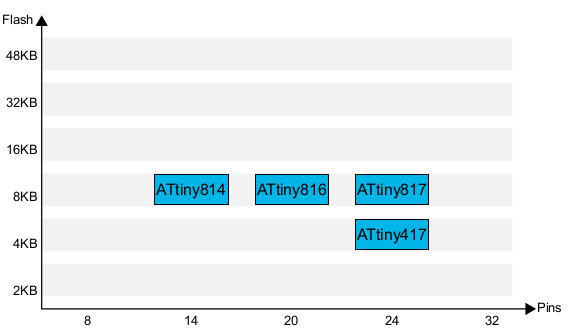
ATtiny417/814/816/817 With Core Independent Peripheral flash size and Pin count
The new 8-bit tinyAVR MCUs are available in QFN andSOIC packages with pricing starting at $0.43 for 10K units. Visit Atmel tinyAVR product page for full technical details about the new MCUs.
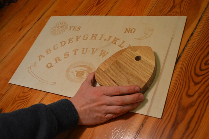
Ouija Board is a flat board marked with the letters of the alphabet, the numbers 0–9, the words “yes”, “no”, along with various symbols and graphics. It uses a small heart-shaped piece of wood or plastic called a planchette. Participants place their fingers on the planchette, and it is moved about the board to spell out words. The Ouija board is also called the spirit board and the talking board.
It was regarded as a parlor game unrelated to the occult until American spiritualist Pearl Curran popularized its use as a divining tool during World War I.
This board seems spooky! But how about combining it with Arduino? This project will introduce Arduino as the mind of this board with the planchette vibrating when it approaches certain letters plus opening a lock!
This project uses Radio-frequency identification (RFID) technology that uses electromagnetic fields to automatically identify and track tags attached to objects. The board has some RFID tags on its back at the exact positions of the letters and the planchette has RFID reader to be able to open the lock while choosing letters the same as the pre-configured password. Thanks to wireless technology used in this project, a radio receiver will control the lock when a password match happens!
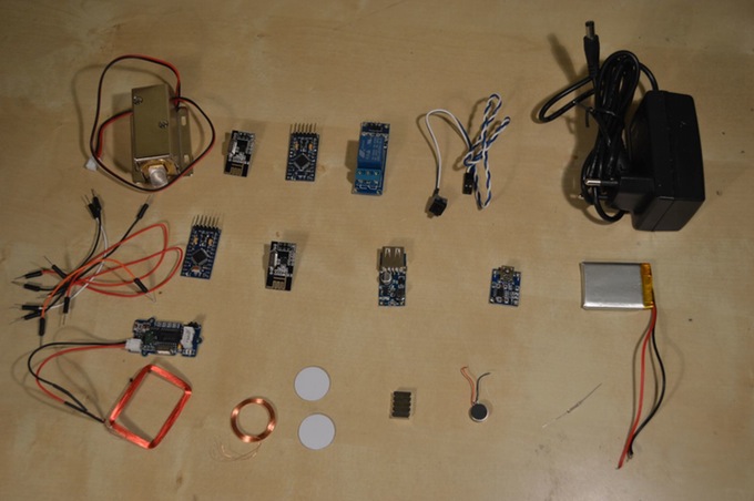
In order to build this project you need to get a Ouija board or make one by yourself. Plus you need the following parts and materials:
You have to use Arduino IDE to program the Arduino mini.
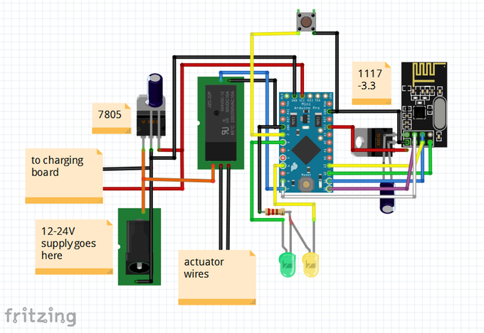
The RFID reader is located within the planchette and it is attached to an Arduino and a battery, keeping in mind providing a place for the antenna in the planchette design. In the other side, the receiver is attached to the actuator and it contains an Arduino Pro Mini, a relay module, an NRF24L01 with a 1117-3.3 regulator attached, a separate 7805 linear regulator with some capacitors and LEDs.
You can check this board in action, the password here is “ Rose”
The sky’s the limit when it comes to choosing an actuator and the lock here in this project is just an example. You can check designs, code snippets, schematics and more detailed information about designing and programming this haunted Ouija board at the project’s page.
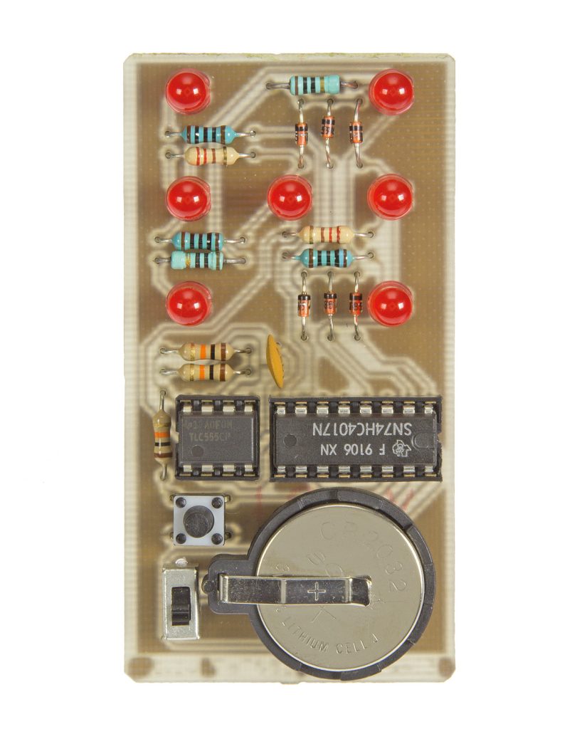
This project is an electronic dice. It consists of seven LEDs positioned like a dice which light up to show the number.
The leds are controlled by a 74HC4017 decade counter IC. Of this IC six outputs are used to drive the LEDs and a seventh output is used to reset the counter. This way it only counts up to six. To light up the correct LEDs, diodes are used. These block the current in one way so other outputs of the IC aren’t affected when LEDs are connected to multiple outputs.
In this video, I’ll walk you through the steps of setting up a Raspberry Pi from the first boot up without a keyboard or monitor. This process requires only a PC or Mac, an ethernet cable, and access to a network router.
How to Setup a Raspberry Pi Without a Monitor or Keyboard – [Link]
educ8s.tv uploaded a new video. This is a 2.8” Arduino Touch Screen Tutorial with the ILI9325 driver. Nick writes:
Hey guys, I am Nick and welcome to educ8s.tv a channel that is all about DIY electronics projects with Arduino, Raspberry Pi, ESP8266 and other popular boards. Today we are going to take a look at this 2.8” touch screen designed for Arduino. As you can see, I have loaded a demo program that displays a button on the screen. When I press the button with my finger, the program displays a message. As demonstrated the touch screen is working fine! Finally we can start building projects with a touch screen which are much more interesting and easier to use.
2.8″ TFT LCD Touch Screen ILI9325 with Arduino Uno and Mega – [Link]
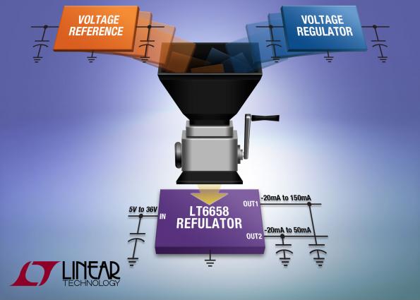
Linear Technology announces the LT6658, a precision voltage reference that incorporates two high current output buffers.
The LT®6658 precision 2.5V dual output reference combines the performance of a low drift low noise reference and a linear regulator. Both outputs are ideal for driving the precision reference inputs of high resolution ADCs and DACs, even with heavy loading while simultaneously acting as output supplies powering microcontrollers and other supporting devices. Both outputs have the same precision specifications and track each other over temperature and load. Both outputs are nominally 2.5V, however each can be configured with external resistors to give an output voltage up to 6V.
LT6658 – Precision Dual Output, High Current, Low Noise, Voltage Reference – [Link]


 Now upload this