

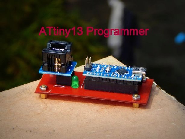
Attiny13 Programmer by Steve Willson Kujur @ instructables.com
How to make an Attiny13 Programmer – [Link]
Attiny13 Programmer by Steve Willson Kujur @ instructables.com
How to make an Attiny13 Programmer – [Link]
Since Internet of Things market is growing exponentially and the use of embedded and pervasive devices is increasing, this may introduces some security threats in the network.
A group of Spanish researchers at the Computer Security Lab, Universidad Carlos III de Madrid have developed a malware, ArduWorm, that targets Arduino Yún, a common platform used in IoT. This malware can bypass all the security provided within Arduino by causing a memory corruption. According to the researchers this malware will be “able to get the control of a Linux-based microprocessor integrated in the device with full privileges, which allows it to install a backdoor and spread as a worm through the compromised network”.
Modern smart devices such as smart phones or tablets are used in social networking, instant messaging or e-commerce. Therefore, these devices store a huge amount of personal and valuable information that is attractive for attackers.
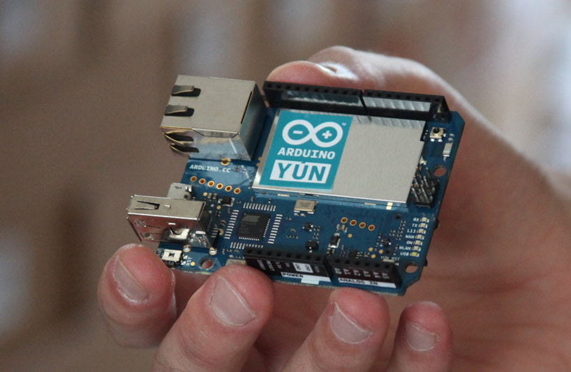
Arduino Yún, is an Arduino board that was specifically designed for IoT applications. It contains an Atheros Microprocessor (MPU) holding a Linux based OpenWrt operating system. This Atheros MPU manages one Ethernet interface and one Wifi card, which make it a suitable device for IoT scenarios. The board has a USB-A port, micro-SD card slot, 20 digital input/output pins, a 16MHz crystal oscillator, a micro USB connection, an ICSP header, and 3 reset buttons.
A security analysis of the Arduino Yún shows that it contains many architectural flaws and since this AVR-based chip has limited resources compared with modern MCU and MPU based on ARM or x86 architectures, classical protections against memory corruption, such as stack overflow protection or memory layout randomization can not be easily deployed.
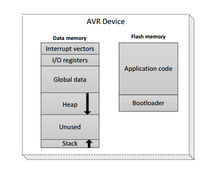
The key of this hack is to get the AVR to run out of RAM. Researchers wrote more and more data into memory until they reached the heap, the memory for control data.
Although the code you want to run is available in flash and it is immutable, recent researches proved that using Return-Oriented Programming (ROP) could inject code into the flash memory. These kind of ROP tricks came in handy for the researchers to write a worm.
Thus, the exploit uses code reuse attacks (Return Oriented Programming and return to-lib) to benefit from a memory corruption vulnerability. ArduWorm has also some infection capabilities and it can automatically spread through neighbor nodes.
During the last few years, malware in tablets and smartphone devices has become one of the main concerns of security researchers. According to Mcafee’s 2015 threat reports up to 1.2 million different malware pieces targeting mobile platforms were detected. A similar report published by the AV company PandaLabs, stated that during 2015 an average of 230.000 different samples were detected on a daily basis.
Researchers are developing ArduWorm as a proof of concept proven in their experimental setup, and they hope that it can motivate research in the design of defensive mechanisms for Arduino and IoT devices.
More details about this malware proof of concept are available at this research paper.
Internet of Things became one of the most important technology trends nowadays, and everyday we have a new board or tool that helps people to create IoT application. Today, we introduce you to “Marvin”, a new IoT board developed at RDM Makerspace.
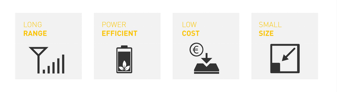
Marvin is an easy to use, plug and play development board for rapid prototyping of IoT solutions with a full size USB port. It is compatible with the open source Arduino platform and works with LoRa communication on LoRa networks.
The board is designed as a USB stick, so you can program it directly into your computer, and once you are done you can plug it into a power bank easily without having to bother with any cables in the process. Marvin is based on the Microchip RN2483 as a LoRa module with 868 & 434 MHz frequency bands, so you can use it anywhere outdoor in Netherlands, and other countries.
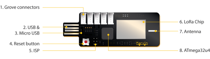
Marvin is also compatible with Grove System, modular, ready-to-use tool sets. Similar to LEGO, it takes a building block approach to assembling electronics. The Grove system consists of a base shield and various modules with standardized connectors. A wide range of Grove modules are available for use within the Grove System.
LoRa, stands for Long Range Low Power, appears to be one of the most popular LPWAN standards. It is a very efficient, light weight way of communicating small messages wireless. The LoRa module is a hardware chip, that is most of the time sleeping, which means you save loads of power.
Marvin board specifications:
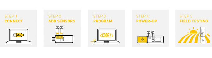
There are five steps to create an IoT project, first connect Marvin to your PC and add sensors, then write your code and upload it to Marvin, finally connect to the power source and enjoy testing your project.
The project has been recently launched on kickstarter, and the developers had surpassed their €10,000 funding target with close to €16,000 raised so far. Ordering Marvin is available for €70 through the campaign page with many other offers.
Let’s connect a solar power inverter for AC voltage output in just 10 minutes.
How to connect a Solar Inverter in 10 minutes – [Link]
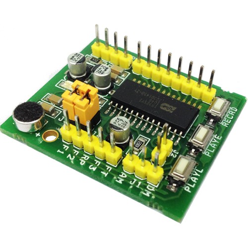
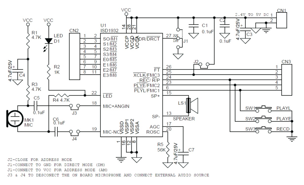
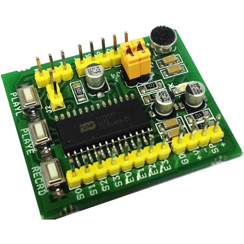
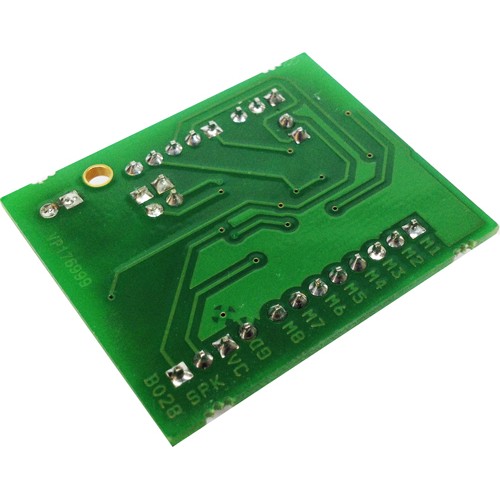
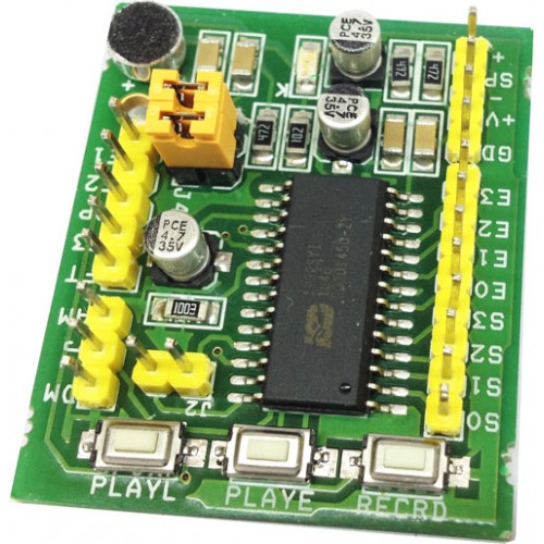
This Module has been designed around Nuvoton’s ISD1932 ChipCorder®, the newest single-chip multiple-message record/playback series with dual operating modes (address trigger and direct trigger) and wider operating voltage range from 2.4V to 5.5V. The sampling frequency can be selected from 4 to 12 kHz via an external resistor, which also determines the duration from 10.6 to 32 seconds. These ICs are designed mostly for standalone applications, and of course, it can be used in conjunction with a microcontroller.
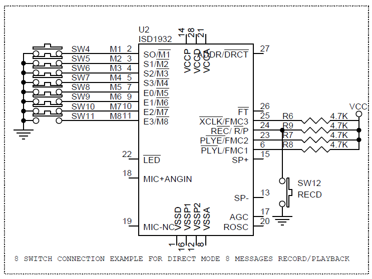
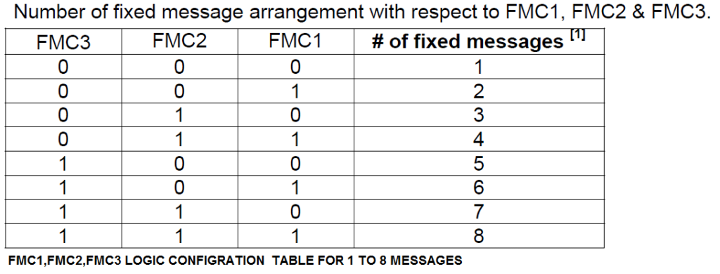
The two operating modes are address trigger and direct trigger. While in address trigger mode, both record and playback operations are manipulated according to the start address and end address specified through the start address and end address pins. However, in direct trigger mode, the device can configure the memory up to as many as eight equal messages, pending upon the fixed message configuration settings. With the record or playback feature being pre-selected, each message can be randomly accessed via its message control pin.
The device has a selectable differential microphone input with AGC feature or single-ended analog input, analog in, under feed-through mode. Its differential Class D PWM speaker driver can directly drive a typical speaker or buzzer.
Sampling Rate or Recording Time Selection
Refer Data Sheet of ISD1932 IC for More information
 Particle is an Internet of Things device platform that enables businesses to quickly and easily build, connect and manage their connected solutions. Particle launched on Kickstarter in 2013 with the vision of making the Internet of Things easy and accessible.
Particle was listed as one of Fast Company’s Most Innovative Companies of 2015 and has been featured in a number of Gartner reports on IoT solutions.
Particle announced that they have been working with the Raspberry Pi Foundation to provide free IoT cloud support for the 10,000,000 Raspberry Pi devices already out in the world.
All Raspberry Pi devices will be able to connect to the Particle Cloud, and to benefit from key IoT features such as secure messaging, over-the-air updates, simplified GPIO control, data visualization, cloud integrations, and batch script execution out of the box.
The Raspberry Pi + Particle integration will bring some unique features to the Raspberry Pi
No more complicated tooling, setup, or scripting to perform simple tasks like trigger a pin, blink an LED, or read a sensor value. With Particle’s Raspberry Pi Agent, you can write simple Arduino and C/C++ code that compiles and runs as an executable on your Raspberry Pi. Take advantage of Particle’s hundreds of embedded libraries to make interacting with sensors and controlling your Pi’s GPIO a breeze.
Access to the Particle Cloud is free! Signing up for the beta is open now and if you are interested you should sign up soon since Particle will be providing access to the first 1,000 Particle accounts at the end of November (21 November) with remaining invitations sent in the following weeks.
Particle’s intention is to provide this integration as a free prototyping resource to all Raspberry Pi developers. Thus, you only start paying when you create a product with more than 25 devices. You can check pricing structure here.
Particle is a scalable, reliable and secure IoT cloud platform and there are already some companies that use Particle to connect and ship their products like IDEO and Keurig. It also has some hardware development kits that work amazingly with the platform.
For more details, you can check Particle documentation and Github. More about this integration is featured on Adafruit ASK AN ENGINEER series where Particle’s CTO Zachary Crockett answers questions and gives a live demo of Raspberry Pi on the Particle Cloud. Check it out!
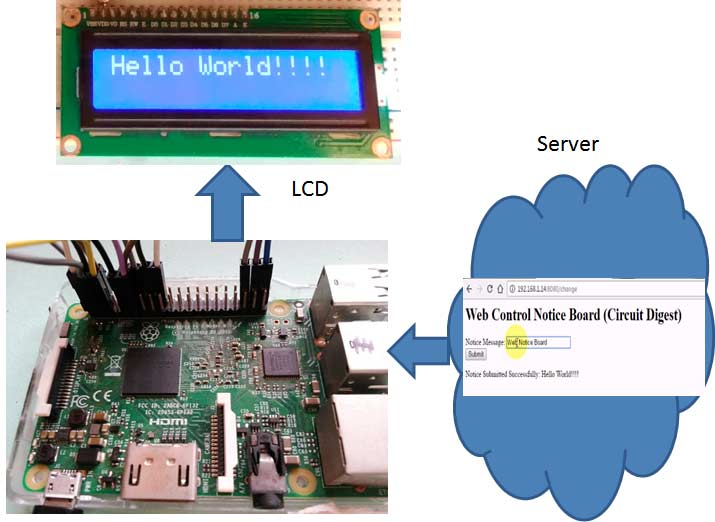
The concept of web controlled notice board is getting more popular day by day for its wide range of applications in the practical field. As an IoT project, simple web controlled notice board can be made using a Raspberry Pi. Saddam at CircuitDigest designed the project where you can send the notice message through web browsers and it will be displayed on a 16×2 LCD display connected to the Pi.
In this Web Controlled Notice Board, we have created a local web server for demonstration, this can be a global server over the internet. At the Raspberry Pi, we have used 16×2 LCD to display message and Flask for receiving the message over the network. Whenever Raspberry receives any wireless message from a Web browser, it displays on the LCD.
The circuit is very easy to make and uses Raspberry Pi as the brain. Few external components are used. You just need to connect the display to Raspberry Pi as per following instructions:
RS, RW and EN pins of LCD are directly connected to pin 18, GND and 23. Data pins of LCD D4, D5, D6, D7 are directly connected to Raspberry Pi’s GPIO 24, 16, 20, 21. A 10K pot is used to control the brightness of LCD.
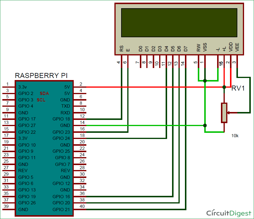
NOTE: If you are not using Raspberry Pi 3, you must use a USB to Wi-Fi adapter for lower versions of Raspberry Pi as they don’t have inbuilt Wi-Fi like Raspberry Pi 3.
Coding is the most important part of this project. Here you need only two codes:
In the HTML code, a simple text box and a submit button are created so that you can enter a Notice Message in TextBox and then submit it to the server by clicking on Submit button.
The Python script is used to send data to the server (Raspberry Pi) and show the data i.e Notice Message on the LCD display. One thing to keep in mind, you should install Flask first using the command:
$ pip install Flask
Now install required libraries for Flask, and define display ports:
from flask import Flask
from flask import render_template, request
import RPi.GPIO as gpio
import os, time

app = Flask(__name__)

RS =18
EN =23
D4 =24
D5 =16
D6 =20
D7 =21
... ......
..... ......
NOTE: You need to copy-paste the HTML code in some text editor and save the file with .HTML extension. Then put this HTML file in the same folder where you have put your interpreted Python Code file.
So this is how you can send a message from your computer or smartphone to the Raspberry Pi LCD and make an IoT-based Wireless Notice Board controlled over The Web.
Today educ8s.tv is going to connect an OLED display to the CHIP 9$ computer in order to monitor its CPU temperature in real time.
I received the CHIP single board computer about a year ago. It is an impressive board, it costs $9 and it offers a 1GHz CPU, 256MB of RAM wifi Bluetooth and many more things. You can watch my review of the CHIP computer by clicking on the card here. As you can see the CHIP computer is a lot smaller than the Raspberry Pi 3 board and of course it costs a lot less. One year later, the software developed for the CHIP computer is mature and we can easily build some projects with it
CHIP Computer Project: CPU Temperature Monitor with OLED display SSD1306 – [Link]
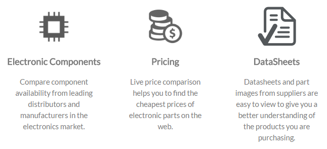
In partnership with OEMSecrets, we are pleased to launch a new section in our website. “Buy Parts” is a price-comparison search engine that helps you save time and money, by finding the cheapest price and the best offer while buying electronic components online.
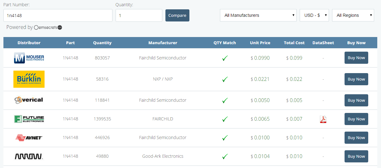
This tool provides an electronic components comparison from leading distributors and manufacturers in the electronics market, such as Farnell, element14, Mouser, TIstore, etc. It also offers datasheets and part images from suppliers to give you a better understanding of products you are purchasing.
The new search engine comes with these features:
It is very simple to use. Just enter a part name in the search box and start saving time and money!
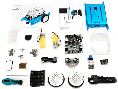
Makeblock was founded in 2012 in Shenzhen as the world’s first open-source robot and programing platform. With more than 400 mechanical components, electronic modules, and software tools, the company is determined to bring meaningful STEM education opportunities and the maker mindset to the mass consumer market to make a real difference in society’s future with robotics.
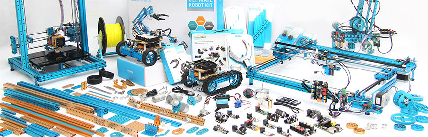
Makerblock has a variety of products and one great product is mBot, a robot better fit education and home use. It is simple to use and affordable, you can get mBot for $24 or with bluetooth for $99.
The mBot is designed especially for mBlock Scratch-based language to help teachers and kids to have hands-on experience about robots and explore STEM education.
Makeblock keeps delivering tutorials about its products and the recent one was a line follower mBot on Insructables.
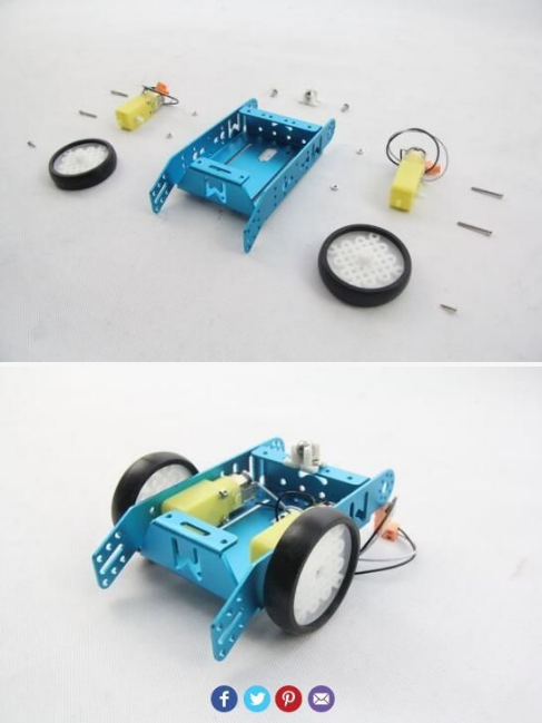
To do this project you need the following tools
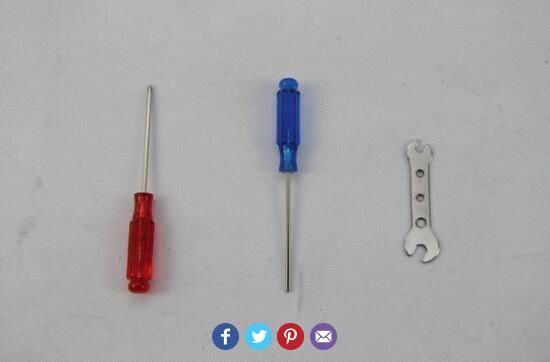
You only have to put each element in the right place and to tighten some screws. The image below shows how to assemble the pieces together.
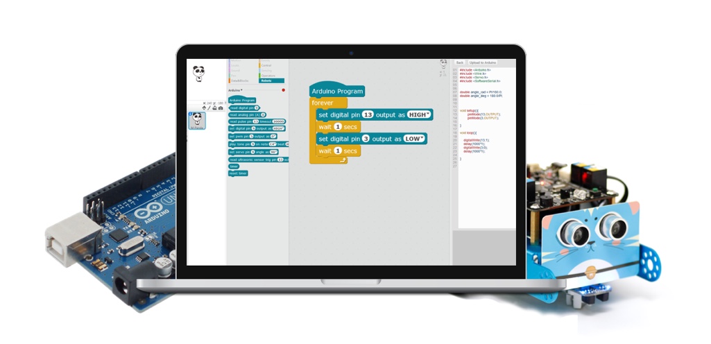
The mBlock is a customized version of scratch. It is easy to use mBlock to interact with electronic modules. To make the project works, you should first program the Control Board (Compatible with Arduino) using this code of mBlock.
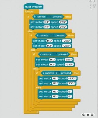
You can also program it using Arduino IDE since it makes it easy to write code, upload it to the I/O board, and interact with mBot. Line following is one simple code for controlling the mBot by Infrared Controller.
#include "mBot.h"
#include "MePort.h"
#include "MeIR.h"
#include "MeDCMotor.h"

MeBoard myBoard(mBot);
double angle_rad = PI/180.0;
double angle_deg = 180.0/PI;
MeIR ir;
MeDCMotor motor_9((MEPORT)9);
MeDCMotor motor_10((MEPORT)10);

void setup() {
 ir.begin();
}

void loop() {
 if(ir.keyPressed(64)){
  motor_9.run(255);
  motor_10.run(255);
 } else {
  if(ir.keyPressed(25)){
   motor_9.run(-255);
   motor_10.run(-255);
  } else {
   if(ir.keyPressed(7)){
    motor_9.run(255);
    motor_10.run(-255);
   } else {
    if(ir.keyPressed(25)){
     motor_9.run(-255);
     motor_10.run(255);
    } else {
     motor_9.run(0);
     motor_10.run(0);
    }
   }
  }
 }
 ir.loop();
}
You can learn more about using Arduino for mBot here.
You can build your own adventure, play some games or make some functions completed autonomously using mBot, such as playing football, ultrasonic obstacle-avoiding and following line. Makeblock is opening wide doors for innovation by making STEM and hands-on experience available for kids.
A new product from MakerBlock is now live on Kickstarter. AirBlock, the first modular drone that can be turned into a hovercraft, car, and more. You can order this drone from the project’s page for $99.
More details and updates can be reached at the official website. Also you can access codes and source files at Github.


