WPS80 digital soldering station

pykqbhvzclsgbk8ktr9gl0b3

James @ seeed.cc show us how to build a DIY digital soldering station using a WPS80 soldering iron.

I always liked soldering tools with good quality. Though I currently have a nice ELV 50 Watts digital soldering station already, I decided to build my own soldering base station using an existing WPS80 soldering iron manufactured by Weller. After looking on the internet to see others DIY projects ,I decided to develop a special one, with several improvements in the design.

WPS80 digital soldering station – [Link]

Sensor IC gives accurate RH and temperature from 2x2mm outline

161109edne-ams_pp_ens210_rgb

ams’ ENS210 sensor module features temperature measurement accuracy of ±0.2°C over the entire range 0°C to 70°C; the device also outputs relative humidity measurements on its I²C interface, enabling, ams says, portable and connected smart home devices to improve performance and implement new features. By Graham Prophet @ edn-europe.com:

The ENS210 is an high performance digital output sensor which monolithically integrates one relative humidity sensor and one high-accuracy temperature sensor. The device is encapsulated in a QFN4 package and includes an I²C slave interface for communication with a master processor.

Transfer Files Between Raspberry Pi and Computer

Sometimes you need to send or receive files from your Raspberry Pi robot, this may be a bit complex process as there is no direct method. You may think about unmounting the SD card from the Raspberry then connecting it to PC, or using a cloud storage to upload and download files, but these methods may increase the complexity of your project.

pi-sd-3

Dexter Industries, an American educational robotics company that develops robot kits, presents in this tutorial three simple ways to transfer files between PC and Raspberry Pi. These methods require a Raspberry Pi with SD card mounted and a PC, and both must be connected to the same network.

The first method is using the Windows file explorer that works on Windows 7 and above. It is very simple, just a right click on computer icon, choose “Map network drive”, and insert your Raspberry IP address. You can then transfer files with the simple copy paste method.

Another way uses File Transfer Protocol (FTP). It is a standard network protocol used to transfer computer files between a client and server on a computer network. There are a lot of free and open-source FTP programs for all platforms, such as FileZilla, WinSCP, SmartFTP, and others.

The following video explains  how to establish a connection between your Raspberry Pi and PC using FileZilla. Once you’ve successfully connected with the FTP software, you can drag and drop files between the Raspberry Pi and the PC.

The last method is editing Raspberry Pi files using Notepad++, a free source code editor which supports several programming languages running under the MS Windows environment. It is a great tool for editing codes and files on your PC, and also on your Raspberry Pi!

After downloading and installing Notepad++ install “NppFTP” plugin, create a profile for your Raspberry Pi connection, and enter the login information. After the connection is successfully created, you should see a file tree appear in the box on the right hand side. You are able now to edit existing files and add new files and folders.

Orange Pi PC2 $20 Quad core Linux Computer

Shenzhen Xunlong Software CO., Limited is now offering  a new addition to the community of single board computers. The latest edition of Orange Pi is the $20 Orange Pi PC 2.
Even though this 85mm×55mm board isn’t as cheap as the $4 VoCore2 Lite, its $20 price tag is justified by the hardware it packs inside. And, it also saves you $15 if you don’t want to go for the $35 Raspberry Pi 3. Orange Pi PC 2 is a single-board quad-core 64-bit computer capable of running Android 4.4, Ubuntu, Debian, Banana Pi, and Raspberry Pi images.

best-seller-orange-pi-pc-h3-support-the-lubuntu-linux-and-android-mini-pc-beyond-raspberry

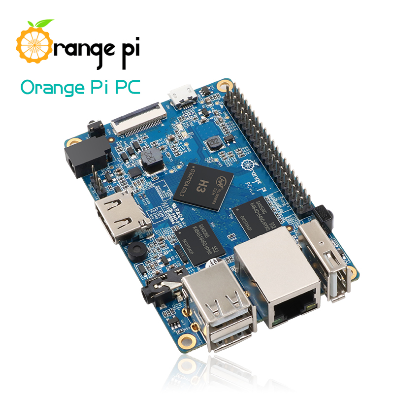
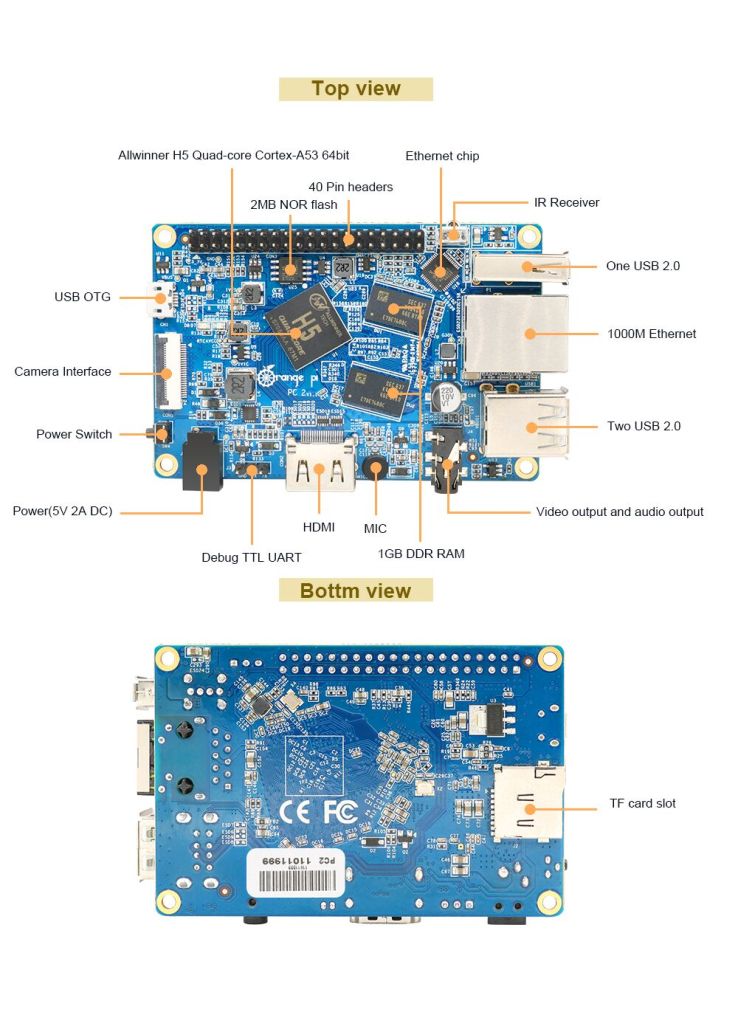
The board includes an Ethernet port and three USB ports. It has 1GB of memory, H5 High Performance Quad-core 64-bit Cortex-A53, and a standalone graphics chip. It supports camera input as well as HDMI out and even has a physical power switch and IR blaster. It takes power using a separate power connector despite the fact that it has a micro-USB port. The absence of WiFi and Bluetooth is a slight turn-down but USB 2.0 ports can be used to add these things.

orangepipc2_info

Full hardware specifications

CPU: Allwinner H5 64-bit Quadcore (Cortex-A53).
RAM: 1GB DDR3.
GPU: Mali-450.
Storage: 2MB NOR Flash, up to 64GB via MicroSD card.
Connectivity: 2xUSB 2.0, 1xUSB 2.0 OTG, HDMI, 10/1000 RJ45, IR receiver, camera interface, 40-pin header.
Audio: 3.5mm jack, inbuilt mic.
Operating System: Ubuntu Debian, Raspbian, Android.
This board is an advanced edition of the recent Orange Pi PC with different CPU, GPU and Ethernet connection.

Getting Started with Orange Pi PC 2

  1. You need to get these accessories to start using your Orange Pi:
    TF card (minimum 8 GB), HDMI to HDMI lead or HDMI to DVI lead (for monitors with DVI input), AV video lead, DC power adapter, keyboard and mouse, plus Ethernet cable/USB WiFi and Audio lead as an option.rms
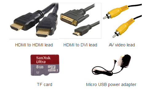
  2. Prepare your TF card
    1. Insert your TF card into your computer. The size of TF should be larger than the OS image size, generally 8GB or greater.
    2. Format the TF card. (using this tool for Windows, and some commands for Linux)
      1. Run fdisk –l  /dev/sdx command to check the TF card node.
      2. Run umount /dev/sdxx to unmount all the partitions of the TF card.
      3. Run sudo fdisk /dev/sdx command to configure TF card. Use o command to delete all partition of TF card and use n command to add one new partition. Use w command to save change.
      4. Run sudo mkfs.vfat /dev/sdx1 command to format the new created partition of TF card as FAT32.
        (x should be replaced according to your TF card node)
    3. Download the OS image from the Downloads webpage.
    4. Unzip the download file to get the OS image
    5. Write the image file to the TF card using this software on Windows and this command on Linux: sudo dd bs=4M if=[path]/[imagename] of=/dev/sdx (x should be replaced according to your TF card node)
  3. Set up your Orange Pi PC following the steps in the diagram
    sketch_map_pipc_en
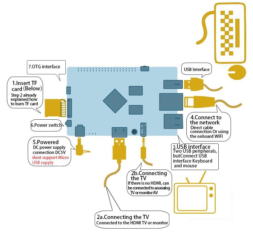
    Note : Avoid using the micro-usb power connector, because micro-usb power does not supply power.
  4. Shut down your board
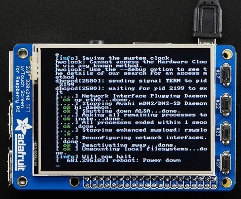
    You can use the GUI to shut down the Orange Pi PC2 safely or just run this command in the terminal:  sudo halt or  sudo shutdown –h now
    This will shutdown the PI safely, (just use the power key to turn off might damage the TF-cards file system). After that you can press the power key for 5 seconds to turn it off. Full guide and any updates on the OS image will be available here.

This open source SBC (single board computer) is a great option to start building IoT devices, DIY projects and for development purposes. You can use it as a mini-computer, a wireless server, music and video player,etc. You should remember that the limit is the sky when it comes to open source boards.

The Orange Pi PC 2 is up for sale on AliExpress and you can get it now for $20. You can apply for free products from Orange Pi through this application by defining your purpose of using the product and following the steps mentioned here.

You can check the official website to find more details and updates about Orange Pi PC2 and other boards from Orange Pi. Codes and source files are available at Github.

PIC16F 28/40 Pin Development Board

pic16f-28-40-pin-development-board-img1

PIC16F 28/40-pin Development Board will help you with your prototyping requirement with any of Microchip’s 28/40-pin of 16F PIC microcontrollers.

Specifications

  • All ports terminating in separate box header connector with 5 VDC source option
  • ICSP connector for programming for the PIC’s with ICD support
  • Jumper selectable onboard pull-up resistors for Port A.4 pin on the microcontroller
  • Bridge in the input provides any polarity DC supply connection to the board
  • 20 MHz crystal source
  • Onboard +5V voltage regulator
  • Four mounting holes of 3.2 mm each
  • PCB dimensions 77 mm x 82 mm

PIC16F 28/40 Pin Development Board – [Link]

PIC16F 28/40 Pin Development Board

pic16f-28-40-pin-development-board-img1

PIC16F 28/40-pin Development Board will help you with your prototyping requirement with any of Microchip’s 28/40-pin of 16F PIC microcontrollers.

Specifications

  • All ports terminating in separate box header connector with 5 VDC source option
  • ICSP connector for programming for the PIC’s with ICD support
  • Jumper selectable onboard pull-up resistors for Port A.4 pin on the microcontroller
  • Bridge in the input provides any polarity DC supply connection to the board
  • 20 MHz crystal source
  • Onboard +5V voltage regulator
  • Four mounting holes of 3.2 mm each
  • PCB dimensions 77 mm x 82 mm

Schematic

pic16f-28-40-pin-development-board-schematic

Parts List

pic16f-28-40-pin-development-board-parts

Photos

pic16f-28-40-pin-development-board-img2

MAC Address Finder

lcds___displays_img_4327

Quickly find the MAC address on devices where doing so isn’t so easy.

Sometimes finding the MAC address of a wireless device is easy and sometimes it’s not. With this project you can find the MAC address of any wireless device in just a few seconds.

What makes this project so simple is the Feather Huzzah. With a few lines of code you can create an access point that other wireless devices can join. Then the Feather will print out the MAC address of that device!

MAC Address Finder – [Link]

Getting Started with 4Duino Wi-Fi

In this project, we will learn how to get started with the ESP8266, an inbuilt 4Duino Wi-Fi module and connect to a local access point. The 4Duino display is used to print the status of the connection for debugging purposes.

The ESP8266 Wi-Fi Module is embedded in the 4Duino. ATmega32U4 communicates and controls the ESP8266 via Software Serial with a default baud rate of 115200 bps. For this purpose pins D8 and D9 are used. However, if the Wi-Fi modules is used in your project then the pins D8 and D9 cannot be utilised in your design.

Getting Started with 4Duino Wi-Fi – [Link]

Yet another Arduino clock

norsk

Sverre Holm blogged about his Arduino clock project:

But I needed another Arduino project as I had made a K3NG morse keyer. I love this keyer because it is unique in supporting a display where you can see what you send. But I wasn’t using the morse keyer all the time, so I wanted the hardware to serve two purposes. That’s the excuse for also making a clock.

Yet another Arduino clock – [Link]

Turn Your Raspberry Pi Into A Wi-Fi Drone Disabler

Note: The information presented here is for educational purposes. This tutorial is designed to help users understand the security implications of using unprotected wireless communications by exploring its use in a popular drone model: the Parrot AR.Drone 2.0. It’s illegal to access computer systems that you don’t own or to damage other people’s property, the techniques should only be performed on devices that you own or have permission to operate on.

Using a Raspberry Pi with a touchscreen, and running a couple of simple Bash scripts, Brent Chapman built a device that will drop Wi-Fi controlled drones right out of the sky with just a tap of your finger.

wifijammer

The device concept is finding the unsecured Wi-Fi access point used by the pilot smartphone or tablet to control the drone, then log on to the drone’s default gateway address, and shuts down the system from the inside without the pilot knowing.

This will only work on some models of drones which use Wi-Fi as the interface between the controller and the drone, such as Parrot’s Bebop and AR.Drone 2.0, that are entirely controlled via Wi-Fi.

The AR.Drone 2.0 is an ideal platform for experimentation and learning thanks to its many impressive features and sensors plus its low cost. It creates an access point named “ardrone2_” followed by a random number, that the user can connect to via a smartphone. This access point is open by default with no authentication or encryption. Once a user connects the device to the access point, he or she can launch the app to begin control of the drone.

raspberry_pi_2298-15

At first, you have to connect the Raspberry Pi with a touchscreen, this guide by adafruit might be helpful. When they are ready, the next step is preparing couple of bash scripts. The first is named “join_network.sh”, and it used to make the Pi automatically join the AR.Drone 2.0 access point.

image4

The second script is named “poweroff.sh”,it will initiate a telnet connection to the drone, then send the command of poweroff, which tells the drone to shut everything down.

image6

The last step is building a “Cantenna”, a DIY directional antenna made of a can to boost the wireless signal. You just need to drill a hole on an empty can to hold a N connector then connect it to Wi-Fi card.

cantenna6

Keep in mind, you should only try this tool on your own personal drones safely and at your own risk. You can find the complete guide at this link at makezine.

TOP PCB Companies