Build Your Own I2C Sensor

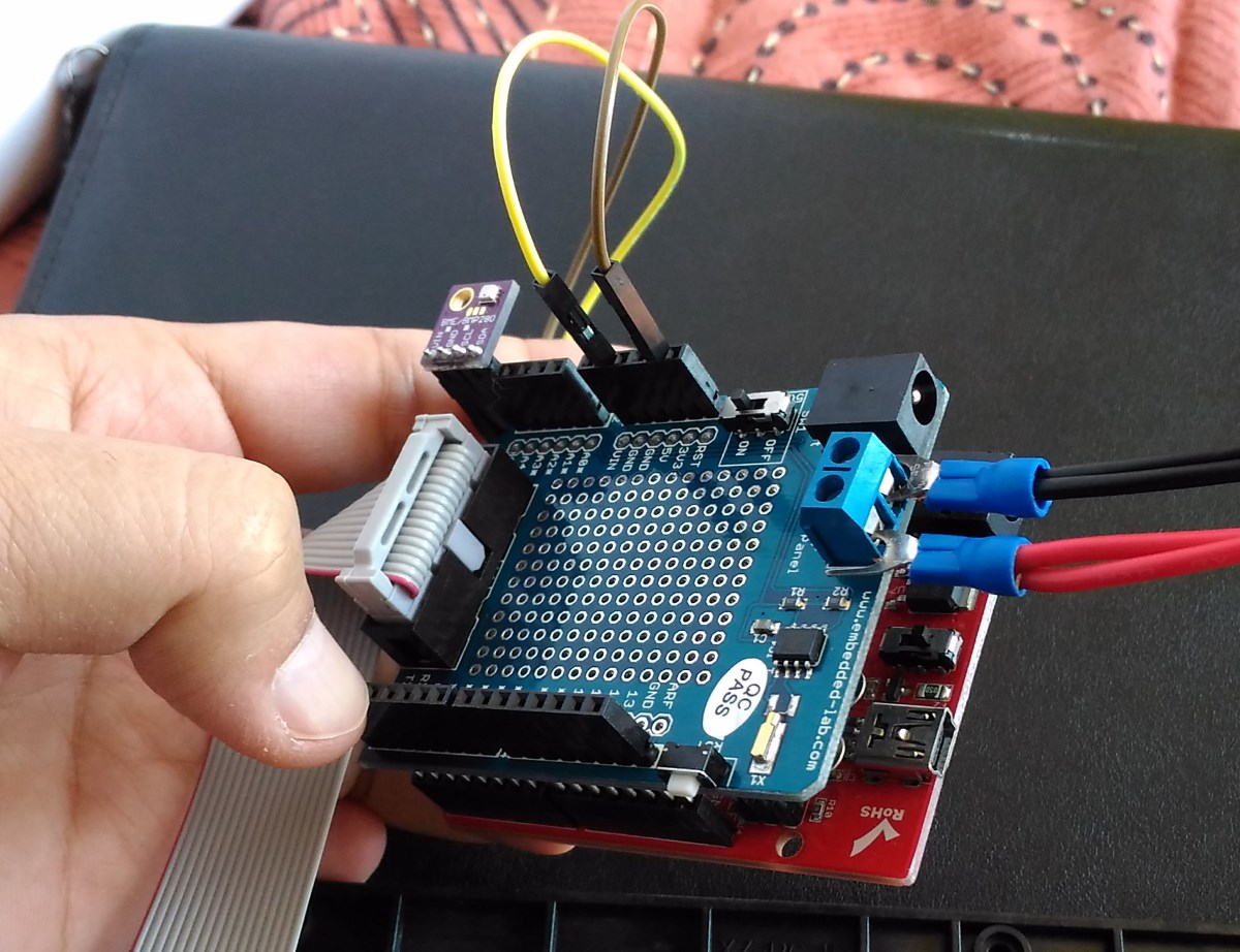
Since Raspberry Pi doesn’t have a built-in ADC (Analog to Digital converter) to read the voltage off from most of sensors, the best solution is to add I2C ADC chips and modules to your project.

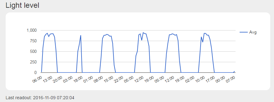
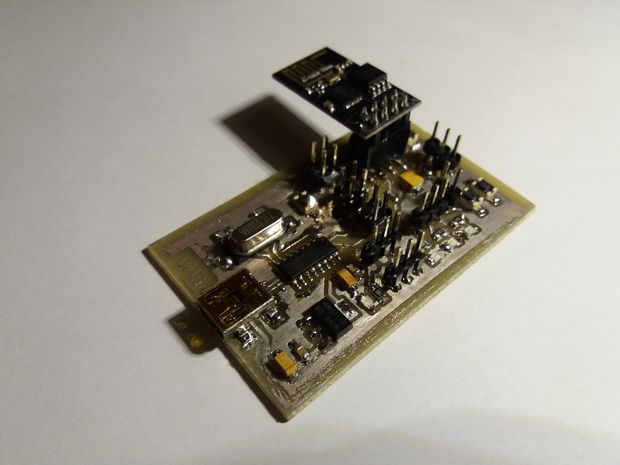
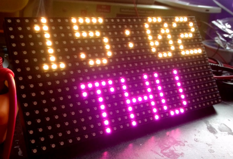
Paweł Spychalski faced this problem while building his own weather station that is based on Raspberry Pi. It collects various data and displays them on dedicated web page and Android app. Every few months he tries to add a new sensor to it. Last time it was a daylight sensor. He added this sensor to his system by using ATtiny85 and it was connected via I2C bus.

ATtiny85 is a member of Atmel tinyAVR series which has 8-bit core and fewer features, fewer I/O pins, and less memory than other AVR series.

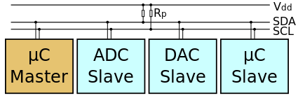
The Inter-integrated Circuit (I2C) Protocol is a protocol intended to allow multiple “slave” digital integrated circuits (“chips”) to communicate with one or more “master” chips. Like the Serial Peripheral Interface (SPI), it is only intended for short distance communications within a single device. Like Asynchronous Serial Interfaces (such as RS-232 or UARTs), it only requires two signal wires to exchange information.

I2C uses only two bidirectional open-drain lines, Serial Data Line (SDA) and Serial Clock Line (SCL), pulled up with resistors. Typical voltages used are +5 V or +3.3 V although systems with other voltages are permitted.

425px-i2c-svg
Sample Inter-Integrated Circuit (I²C) schematic with one master (a microcontroller) and three slave nodes

Most of developers use I2C to connect to sensors with the help of the Arduino “Wire” library or “i2c-tools” on the Pi, but it is rare to see someone that is actually building the I2C slave device. Paweł’s project uses TinyWireS library, a slave-mode SPI and I2C library for AVR ATtiny Arduino projects.

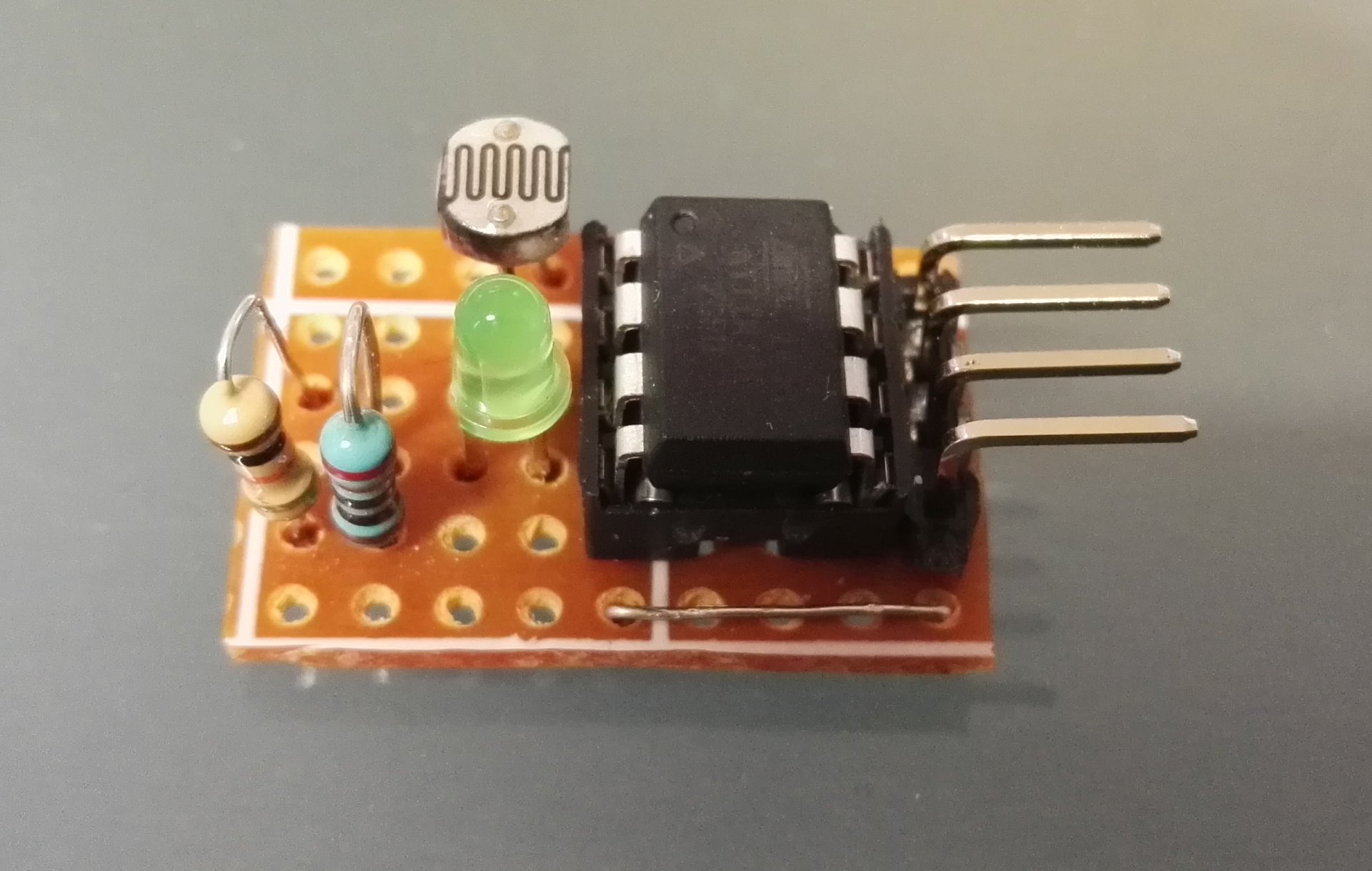
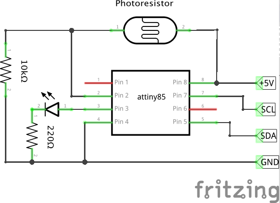
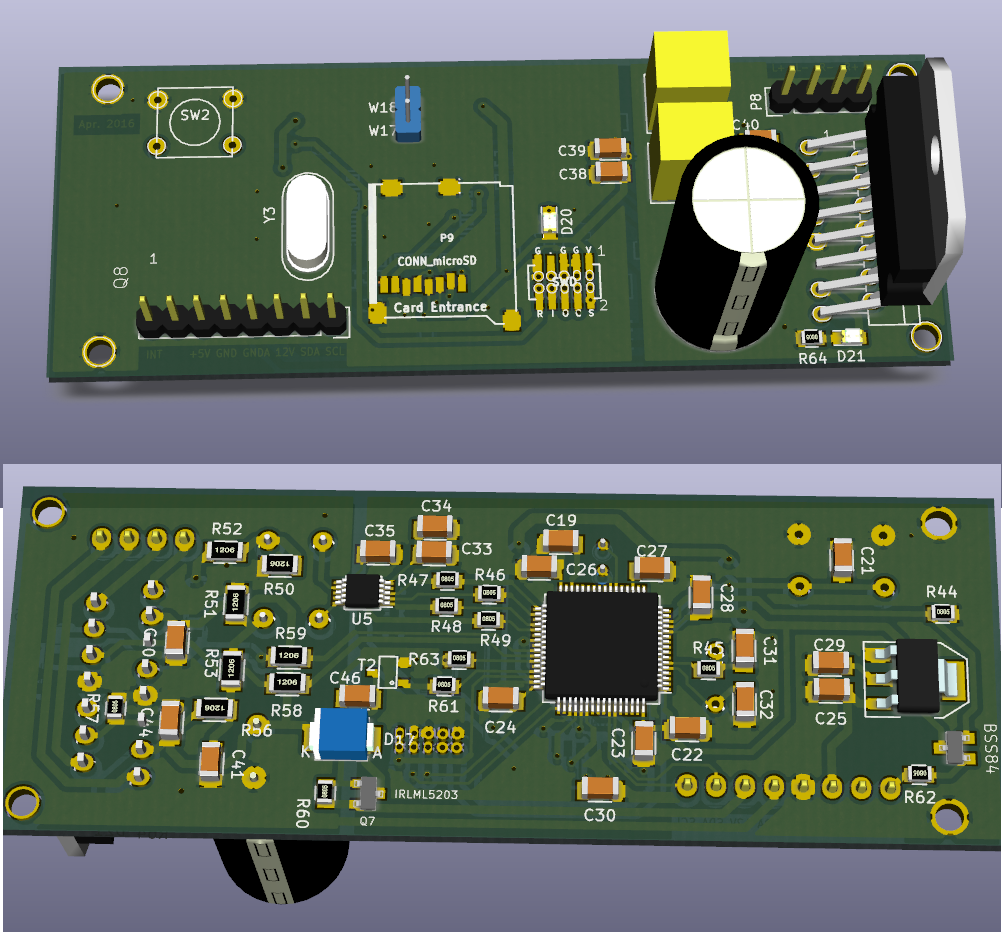
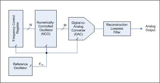
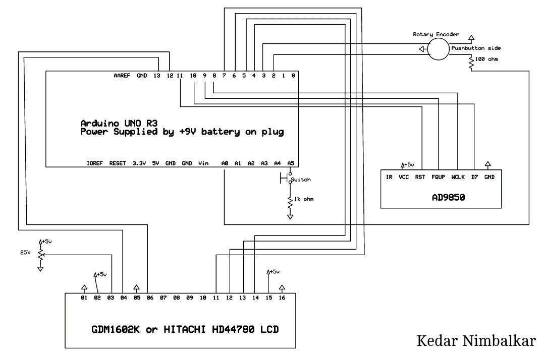
This diagram shows how to build analog to digital converter using ATtiny85 and connect it to any device (Raspberry Pi, Arduino) using I2C bus. Here photoresistor has been used, but any analog meter will be fine: temperature, potentiometer, moisture…

ATtiny85 directly connected to Raspberry Pi via I2C, photoresistor with 10kOhm pull down connected to ATtiny85 and signal LED.

attiny_photoresistor_i2c
ATtiny85 directly connected to Raspberry Pi via I2C, photoresistor with 10kOhm pull down connected to ATtiny85 and signal LED.

For reading data you can use this code. ATtiny sends current measurement as two 8 bit value. First older bits, then younger 8 bits.

Wire.requestFrom(0x13, 2);    // request 2 bytes from slave device #0x13

int i =0;
unsigned int readout = 0;

while (Wire.available()) { // slave may send less than requested
 byte c = Wire.read(); // receive a byte as character

 if (i == 0) {
  readout = c;
 } else {
  readout = readout << 8;
  readout = readout + c;
 }

 i++;
}

Serial.print(readout);

To do this project you need to use Arduino IDE 1.6.6., TinyWireS library,ATtiny45/85 board, plus an 1MHz internal oscillator.

Watchdog timer interrupts ATtiny every few minutes, measures voltage, filters it and stores in memory. Every time read operation is requested, last filtered ADC value (10 bits as 2 bytes). I2C support is provided by TinyWireS library that configures ATtiny USI (Universal Serial Interface) as I2C slave.

/**
* This function is executed when there is a request to read sensor
* To get data, 2 reads of 8 bits are required
* First requests send 8 older bits of 16bit unsigned int
* Second request send 8 lower bytes
* Measurement is executed when request for first batch of data is requested
*/
void requestEvent() {
 TinyWireS.send(i2c_regs[reg_position]);

 reg_position++;
 if (reg_position >= reg_size) {
  reg_position = 0;
 }
}

/*
* Setup I2C
*/
TinyWireS.begin(I2C_SLAVE_ADDRESS);
TinyWireS.onRequest(requestEvent); //Set I2C read event handler


Bright by day, dark by night

This cool weather station and its need of daylight sensor is only an example. The amazing thing is that you can now build new I2C sensors and introduce new modules to your projects easily following Paweł’s steps.

For more details about this project you can check Github and the weather station website.

SD Card Sound Player

audio3

fasoft @ elektormagazine.com has a new project proposal about a SD Card Sound Player.

Searching for a powerful gong or acoustic notifier? The “Card Sound” consists of audio amplifier TDA7266 having 2x 7 W output, the AD converter CS4344, one STM32F401 and a slot for micro sd card. Objective is to play different sounds stored on an SD card. Current schematic has one TWI port for control. Amend other interfaces like RS-485, UART, SPI etc. is also possible.

SD Card Sound Player – [Link]

LTC5596 – 100MHz to 40GHz Linear-in-dB RMS Power Detector

1

The LTC5596 is a high frequency, wideband and high dynamic range RMS power detector that provides accurate, true power measurement of RF and microwave signals independent of modulation and waveforms. The LTC5596 responds in an easy to use log-linear 29mV/dB scale to signal levels from –37dBm to –2dBm, at accuracy better than ±1dB error over the full operating temperature range and RF frequency range, from 200MHz to an unprecedented 30GHz. In addition, the device’s response has ±1dB flatness within this frequency range. A wider frequency range can be used, from 100MHz to 40GHz, however with slightly reduced accuracy at the frequency extremes. Its RF input is internally 50Ω matched from 100MHz to 40GHz, making the device very easy to use at any band within its useful frequency range.

LTC5596 – 100MHz to 40GHz Linear-in-dB RMS Power Detector – [Link]

Controlling A Robotic Arm By Gestures Using Kinect Sensor & Arduino

B.Avinash and J.Karthikeyan had developed a robotic arm that mimic their moves using a Kinect sensor with MATLAB Simulink and an Arduino. The arm was built based on servo motors that replicate the right arm shoulder, elbow and hand movements.

college-project-final-year-2016-9

ic568992
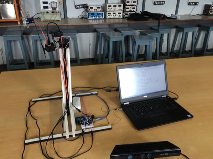
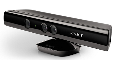
The Kinect sensor is a horizontal bar of motion sensing input devices which enable users to control and interact with their computers through a natural user interface using gestures and spoken commands.

The sensor consists of a RGB camera, depth sensor, and multi-array microphone running proprietary software. It provides full-body 3D motion capture, facial recognition, and voice recognition capabilities.

MATLAB Simulink is a graphical programming environment for modeling, simulating and analyzing multidomain dynamic systems. It supports simulation, automatic code generation, and continuous test and verification of embedded systems.

Simulink is developed by Mathworks, and it offers integration with MATLAB environment, enabling developers to incorporate MATLAB algorithms into models and export simulation results for further analysis. Simulink is widely used in automatic control and digital signal processing for multidomain simulation and Model-Based Design.

To build a similar gesture-controlled arm you need these components:

Thanks to Simulink support for Kinect, the computer collects data from the connected kinect device and translates them into servo angles in MATLAB. These angles are sent to the servos through the arduino via TTL device, resulting movement of the arm with a slight delay.

TTL - Arduino & Arduino - Servo Connection Schematic
TTL – Arduino & Arduino – Servo Connection Schematic
Simulink Model
Simulink Model

This project has been chosen in the week’s (29/10/2016) Pick of the Week during Matlab Simulink Hardware Challenge 2016, and it also had won the 4th place in “MATLAB International Simulink Hardware Challenge 2016“.

Arduino code, other files and resources are reachable at this instructable and this hackster.io page.

122 GHz On-chip Radar

Silicon technology has made tremendous progress towards ever higher device cut-off frequencies. Nowadays all RF components for mm-Wave sensing applications up to 120 GHz can be realized.
Silicon Radar is a german company that designs and delivers Millimetre Wave Integrated Circuits (MMICs) on a technologically advanced level, manufactured in affordable Silicon-Germanium-Technology (SiGe). It has just introduced new development kits using GHz CMOS radar MMICs, which are built using SiGe or SiGe:C from IHP.

Silicon Radar participated in the European Commission 7th Framework Success project,  to develop ways to mass produce silicon mm-Wave SoCs at low cost – with STMicro, IHP, Evatronix, Selmic, Hightec, Bosch, the Karlsruhe Institute of Technology and the University of Toronto.

20161017130553_silicon-radar

The development kits are:

assy_easyradarkit_270
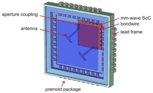
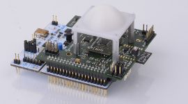
EasyRadar is for evaluating all of the firm’s TX/RX radar chips, and is “great for beginners and pros who want to start development and tweak system parameters”, said Silicon Radar.

EasyRadar features:

  • programmable FMCW parameters
  • signal processing
  • target recognition
  • web-based GUI
  • USB or wireless LAN communication with PC

The kit includes:

  • 122 GHz radar front end (see photo above)
  • 24 GHz radar front end (see lower photo)
  • controller board
  • baseband board with WiFi
  • lens for 122 GHz

You can download the user guide and the protocol description

simpleradar_270
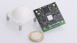
SimpleRadar is available to evaluate the firm’s 122 GHz radar front end.

It has the same functionality as the EasyRadar but is smaller (40 x 40mm), and can be used as a Wi-Fi-enabled radar sensor with integrated target recognition.

It has the following features:

  • programmable FMCW parameters
  • signal processing
  • target recognition
  • web-based GUI
  • USB communication with PC or over wireless LAN

You can check its user guide and the protocol description

“We offer high frequency circuits for radar solutions, phased-array-systems and wireless communications, for both custom specific ASIC design and supply of standard circuits in frequency range from 10GHz X-band up to 200GHz and above,” said the firm.

Possible applications using the kits are:

  • distance sensing applications such as industrial sensing (distance, speed, material characterisation),
  • public and private safety (motion detectors, even behind wall paper),
  • automotive (wheel suspension measurement, pedestrian safety),
  • replacement of cheap ultrasonic sensors (distance measurement)

For more details, you can download the full package. Since it is password-protected, you have to contact the company to gain access.

DueProLogic – USB-CPLD Development System

ept-4ce6-af-d2-front-diagonol-white-background_1659x843_001

The DueProLogic is a complete FPGA Development System designed to easily get the user started learning and creating projects.

The DueProLogic makes programmable logic easy with an all inclusive development platform. It includes an Altera Cyclone IV FPGA, on board programming, four megabit configuration flash, and an SD connector for add on memory. You can create your HDL code, program it into the flash and interact with the hardware via a Windows PC.

DueProLogic – USB-CPLD Development System – [Link]

Environmental data display on an RGB matrix panel

In this tutorial, I have described how to use a 16×32 RGB matrix panel with Arduino Uno for colorful display of environmental data captured locally using Bosch BME280 sensor. BME280 is a fully integrated environmental unit from Bosch that combines sensors for pressure, humidity, and temperature in a tiny 8-pin metal-lid LGA package. The RGB LED matrix panel consists of 512 bright RGB LEDs arranged in 16 rows and 32 columns. The row and column driver circuits are built on the back side of the matrix panel. The data and control signal pins are accessible through a HUB75 (8×2 IDC) connector. It requires 12 digital I/O pins of Arduino Uno for full color control. The display panel also comes with a RGB connector shield for Arduino Uno and necessary cables for easy wiring between the RGB panel and the Arduino board.

demo6
16×32 RGB LED matrix panel

The connector shield also features the DS1307 RTC chip on board along with a CR1220 coin-cell battery holder. The I2C pins of the DS1307 chip are pre-wired to A4 and A5 pins of the shield. The BME280 is also I2C compatible and uses the same pins for data and clock. I have written a firmware for Arduino to read temperature, humidity, and pressure data from BME280, and time and date from DS1307 chip, and display all these data on the RGB panel with different color and some animation. You can find rest of the details here.

setup5
RGB connector shield consists of DS1307 RTC on board


12$ 30MHz signal generator using Arduino

A signal generator is an electronic device that generates electronic signals and waveforms. These electronic signals are either repeating or non-repeating as per the requirements and field of applications. It is generally used in designing, testing, troubleshooting and repairing electronic devices. A signal generator can generate various kinds of waveforms. Most common are the sine wave, square wave, sawtooth wave and triangular wave.

This instructable shows a full guide on how to make a 30 MHz signal generator for 12$, using an Arduino and an AD9850 DDS synthesizer module. The circuit is pretty simple and small enough to fit in your pocket. Kedar Nimbalkar, the author of the instructable, says:

A precession signal generator is very easy and affordable to make using an Arduino and DDS synthesizer (ad9850) . It’s World’s first smallest portable signal generator.

You can make decent 0 -30 MHZ frequency Signal generator only in 12$ .

30 MHz signal generator using Arduino

Parts List:

1. Arduino Pro mini
2.AD9850 (DDS Synthesizer)
3.16×2 LCD Display ( Hitachi HD 44780 )
4.Rotary Encoder
5. CP2102 (or any USB to serial converter)

I think you are familiar with all of the above items except the AD9850 (DDS Synthesizer). First of all, you need to know what does DDS stand for.

Direct Digital Synthesizer Block Diagram


Direct digital synthesizer (DDS) is a type of frequency synthesizer used for creating arbitrary waveforms from a single, fixed-frequency reference clock. A basic Direct Digital Synthesizer consists of a frequency reference, a numerically controlled oscillator (NCO) and a digital-to-analog converter (DAC).


AD9850 (DDS Synthesizer):

The AD9850 is a highly integrated device that uses advanced DDS technology coupled with an internal high-speed, high-performance D/A converter and comparator to form a digitally programmable frequency synthesizer and clock generator function. When referenced to an accurate clock source, the AD9850 generates a spectrally pure, analog output sine wave. In a nutshell, AD9850 works on DDS (direct digital synthesis ) which can generate analog waveforms with digital input.
Read the datasheet to learn more.
The AD9850 DDS Module signal generator
The AD9850 DDS Module

Circuit Diagram of Signal Generator:

The circuit diagram is very simple. You can make it on a breadboard, or just solder components end to end to make it more compact.

Signal Generator Circuit Diagram
Arduino Based Signal Generator Circuit Diagram

The Arduino sends digital signals to AD9850 and the module generates analog output Sine wave. The display, which is connected to Arduino, shows output frequency and step increment/decrement value. The rotary encoder is for changing frequency. Though the AD9850 module can generate up to 40 MHz frequency, but after 30 MHz the output frequency becomes unstable. So in this circuit, the maximum frequency is limited to 30 MHz.

You can make a decent 0-30 MHz frequency signal generator for only 12$ . If you are pro “overclocker”, then 40 MHz in same price .

The signal generator runs on 5 Volt power supply and current should not exceed 270mA.

Arduino Sketch:

The Arduino code is HERE.

Output:

Output Response of Arduino Based Signal Generator

Watch the video which demonstrates the 12$ signal generator.

Ultralow Power Transistors Function for Years Without Batteries

Researchers at Cambridge University have just achieved a spectacular breakthrough in electronics design. They have developed new ultralow power transistors that could function for months or even years without a battery. These transistors look for energy from the environment around, thus reducing the amount of power used.

crop_15

Dr Sungsik Lee, one of the researchers at the Department of Engineering says, “if we were to draw energy from a typical AA battery based on this design, it would last for a billion years.” The new design could be produced in low temperatures and they are versatile enough to be printed on materials like glass, paper, and plastic.

Basically, transistors are semiconductor devices that function like a faucet. Turn a transistor on and the electricity flows,  turn it off and the flow stops. When a transistor is off however, some electric current could still flow through, just like a leaky faucet. This current, which is called a near-off-state, was exploited by the engineers to power the new transistors.

power-consumption

schematic
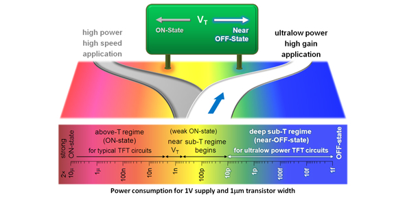
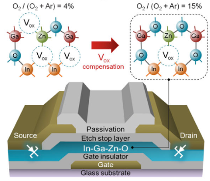
The researchers developed a thin-film transistor (TFT) from In-Ga-Zn-O (indium-gallium-zinc-oxide) thin films. To make the material less conductive, the films were fabricated to avoid oxygen vacancies. Eventually, they achieved a new design that operates in near the OFF state at low supply voltages (<1 volt) and ultralow power (<1 nanowatt).

The transistor’s design also utilizes a ‘non-desirable’ characteristic, namely the ‘Schottky barrier’ to create smaller transistors. Transistors today cannot be manufactured into smaller sizes since the smaller a transistor gets, the more its electrodes influence each other, causing a non-functioning transistor.The use of the Schottky barrier in the new design creates seal between the electrodes that make them work independently from each other.

“We’re challenging conventional perception of how a transistor should be,” said Professor Arokia Nathan of Cambridge’s Department of Engineering, the paper’s co-author. “We’ve found that these Schottky barriers, which most engineers try to avoid, actually have the ideal characteristics for the type of ultralow power applications we’re looking at, such as wearable or implantable electronics for health monitoring.”

According to Arokia Nathan of Cambridge’s Department of Engineering, the second author of the paper, this new design can see use in various sensor interfaces and wearable devices that require only a low amount of power to run. Professor Gehan Amaratunga, Head of the Electronics, Power and Energy Conversion Group at Cambridge’s Engineering Department sees its use in more autonomous electronics that can harness energy from their environments similar to a bacteria.

As electronic devices become more compact and powerful, conventional methods for manufacturing electrical components simply won’t do. This unconventional way will not only consume minimum power but it also will open up new avenues for system design for the Internet of Things and ultralow power applications.

This research was introduced as a research paper in Science magazine on October 2016. More details are available here  “Subthreshold Schottky-barrier thin-film transistors with ultralow power and high intrinsic gain”.

TOP PCB Companies