Two New Orange Pi IoT Boards

Shenzhen Xunlong Orange Pi boards are low price boards and have huge support on communities such as Armbian, but two new Orange Pi boards might make the company even more relevant in the development board space.

First, the company has released the tiny, and hopefully ultra cheap, Orange Pi Zero board with Allwinner H2+ processor and 256MB/512MB DDR3 SDRAM. It’s an open-source 48 mm × 46mm single-board computer that can run Android 4.4, Ubuntu, and Debian.

orangepizero_info

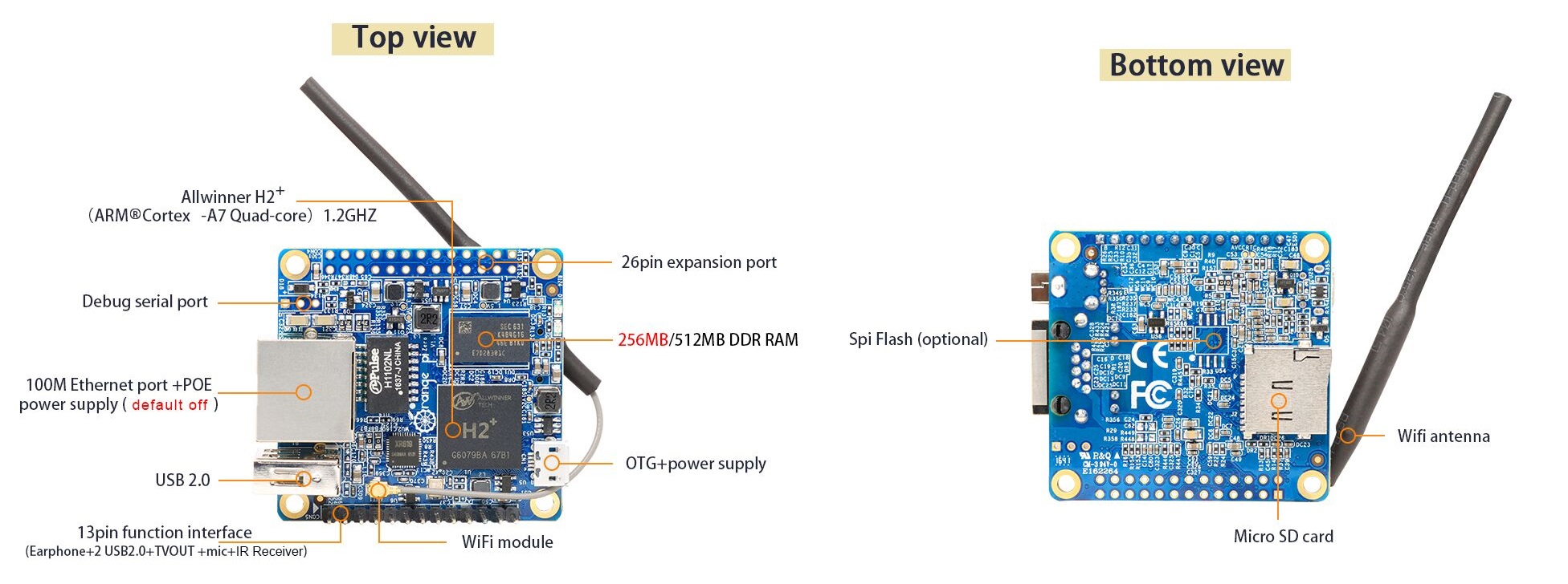
Orange Pi Zero is similar to NanoPi NEO board but with difference in the processor and both Ethernet and wireless connectivity. It comes with these hardware specifications:

  • CPU: H2 Quad-core Cortex-A7 H.265/HEVC 1080P.
  • GPU: Mali400MP2 GPU @600MHz, Supports OpenGL ES 2.0
  • Memory (SDRAM): 256MB/512MB DDR3 SDRAM (shared with GPU)
  • Onboard Storage: Or Flash(2MB Default not posted)
  • Onboard Network: 10/100M Ethernet RJ45 POE is default off.
  • Onboard WIFI: XR819, IEEE 802.11 b/g/n
  • Audio Input: MIC
  • Video Outputs: Supports external board via 13 pins
  • Power Source: USB OTG can supply power
  • USB 2.0 Ports: Only One USB 2.0 HOST, one USB 2.0 OTG
  • Buttons: Power Button
  • Low-level peripherals: 26 Pins Header, compatible with Raspberry Pi B+, 13 Pins Header, with 2x USB, IR pin, AUDIO (MIC, AV)
  • LED: Power led & Status led
  • Key: POWER
  • Supported OS: Android, Lubuntu, Debian, Raspbian

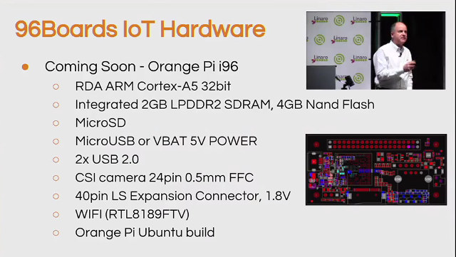
Linaro has announced that an Orange Pi i96 board is coming soon. It is a good choice for making smart gadgets, robots, or drones with wireless capabilities on cheap development board.

The board has features not found on competitive boards. It won’t be based on any Allwinner processors however, but instead it features an RDA Micro Cortex-A5 processor with 256 MB on-chip RAM, 512 MB on-chip NAND flash, a microSD card, two USB 2.0 ports, a CSI camera connector, and WiFi 802.11 b/g/n connectivity.

“We can’t wait to see what developers are going do with this in the areas of vision and recognition systems and robotics,” said George Grey, CEO of Linaro.

orange-pi-i96-640px

The Orange Pi i96 also has a camera interface, which is important to give computer vision to robots and drones. The board is based on specifications set by 96boards, an organization encouraging the development of ARM-based board computers. The exact shipment date for Orange Pi i96 is not yet available.

“Linaro is also encouraging the development of other IoT boards. In the near future, there will be billions of IoT devices collecting and sending information, and more boards will be used to support this growing ecosystem”, Grey said.

Source: CNXSoftware

Plotclock with a DS3231 Real Time Clock and an Arduino UNO

educ8s.tv uploaded a new video. This time is a plotter clock using DS3231 and Arduino.

Hey guys, I am Nick and welcome to educ8s.tv a channel that is all about DIY electronics projects with Arduino, Raspberry Pi, ESP8266 and other popular boards. Today we are going to build this Plot Clock, a device that does not use a display to tell the time, but it writes the time using a whiteboard marker. Let’s see it in action. Every minute, it erases the previous time, so it has a clear surface to write on, and then it writes the current time with the marker. Impressive isn’t it? The brains of this project is an Arduino Uno. I am also using a DS3231 Real Time clock module in order to keep the time. Let’s now see how to build this project.

Plotclock with a DS3231 Real Time Clock and an Arduino UNO [Link]

LM35 LCD Thermometer using PIC16F676

lm35-themometer-pic16f676-img

lcd

This is a simple circuit to measure the temperature of any environment and display it on a 16×2 LCD module (C013). This is just an temperature indicator project and not a controller circuit. Circuit works with 7-9V DC.

The circuit uses a Microcontroller to read a LM35 Temperature sensor and display the results on the LCD. The onboard ADC on the microcontroller converts the analog signal from the LM35 sensor, computes the results and displays it on the LCD.

Specifications:

  • Preset PR1 allows the user to adjust the ADC Reference voltage for the project.
  • Temperature sensor (LM35) is connected by a relimate connector at CN3 connector.
  • U3 is a voltage regulator IC, 7805 which provides a regulated voltage to the entire circuit.
  • D2 is a reverse polarity protection diode to prevent against wrong polarity connection of DC supply at connector CN1.
  • LCD Module – C013 is connected at connector marked U1. Please solder corresponding pins marked on this PCB with the One marked on the

Schematic

lm35-themometer-pic16f676-schematic

lm35-themometer-pic16f676-schematic-lcd

Parts List

lm35-themometer-pic16f676-parts

lm35-themometer-pic16f676-parts-lcd

AT89SXX Development Board

at89sxx-development-board-img2

Our AT89Sxx Development Board provides a very simple and cost effective prototyping platform.  The compact design provides connection to all the pins of the microcontroller for the user.

Features

  • Prototyping solution available for 40-pin AT89xx series microcontroller from ATMEL
  • All the four ports available to the user via standard 10 pin box header with supply of 5 VDC for interfacing circuits
  • ISP (In circuit Serial Programming) connector available for chips with ISP support
  • 11.0592 MHz crystal on board
  • Pull-up resistor network for Port 0 of the microcontroller
  • UART level shifter MAX232 IC, on board for easy connection of the board to the RS232 devices
  • Jumper selectable connection available for connecting the UART level Shifter to the port pins
  • On board voltage regulator available for sourcing regulated 5V @ up to 1A voltage to the board and connecting circuit
  • Power-On LED indicator
  • AUX Power source of 5 VDC available on a PBT connector for sourcing DC supply to interfacing circuits
  • Four mounting holes of 3.2 mm each
  • PCB dimensions 74 mm x 97 mm

AT89SXX Development Board – [Link]

Nanobots Fight Cancerous Cells

Researchers from Polytechnique Montréal, Université de Montréal and McGill University have just achieved a spectacular breakthrough in cancer research. They have developed new nanorobotic agents capable of navigating through the bloodstream to administer a drug with precision.

Professor Sylvain Martel is holder of the Canada Research Chair in Medical Nanorobotics and the Director of the nanorobotics laboratory at Polytechnique Montreal, where he studies medical applications of nanotechnology. Martel and his team have demonstrated major progress with a new technology that could revolutionize cancer treatment by using guided micro-transporters to deliver drugs. Thus cancerous cells can be locally targeted and then stop their growth.

new_version-b-low

This breakthrough in cancer-fighting research would ditch chemotherapy for nanorobots that fight cancer inside the human body. This research was published in the prestigious journal Nature Nanotechnology in an article titled “Magneto-aerotactic bacteria deliver drug-containing nanoliposomes to tumour hypoxic regions.” The article notes the results of the research done on mice, which were successfully administered nanorobotic agents into colorectal tumours.

“These legions of nanorobotic agents were actually composed of more than 100 million flagellated bacteria — and therefore self-propelled — and loaded with drugs that moved by taking the most direct path between the drug’s injection point and the area of the body to cure,” explains Professor Martel “The drug’s propelling force was enough to travel efficiently and enter deep inside the tumours.”

When they enter a tumour, the nanorobotic agents can detect in a wholly autonomous fashion the oxygen-depleted tumour areas, known as hypoxic zones, and deliver the drug to them. This hypoxic zone is created by the substantial consumption of oxygen by rapidly proliferative tumour cells. Hypoxic zones are known to be resistant to most therapies, including radiotherapy. But gaining access to tumours by taking paths as minute as a red blood cell and crossing complex physiological micro-environments does not come without challenges. So Professor Martel and his team used nanotechnology to do it.

Scanning electron microscopy images of unloaded Magneto-aerotactic(MC-1) bacteria (Left) and when loading it with the drug (right)

To move around, bacteria used by Professor Martel’s team rely on two natural systems; a kind of compass created by the synthesis of a chain of magnetic nanoparticles allows them to move in the direction of a magnetic field, while a sensor measuring oxygen concentration enables them to reach and remain in the tumour active regions. By harnessing these two transportation systems and by exposing the bacteria to a computer-controlled magnetic field, researchers showed that these bacteria could perfectly replicate artificial nanorobots of the future designed for this kind of task.

“These results represent a novel therapeutic avenue for patients with hard-to-treat cancers, once the approach has been validated in human trials,” says co-author Nicole Beauchemin, a professor of Biochemistry, Medicine and Oncology at McGill and researcher at the Rosalind and Morris Goodman Cancer Research Centre.

An interview with Professor Martel with RT America to explain how the nanorobots are better at targeting cancer cells than current cancer treatments.

This work was supported by many research centers and consortiums in Canada such as the Consortium québécois sur la découverte du médicament (Québec consortium for drug discovery – CQDM), the Canada Research Chairs, the Natural Sciences and Engineering Research Council of Canada (NSERC) and the Research Chair in Nanorobotics of Polytechnique Montréal.

To overcome some limitations of the previous approach, professor Martel has been leading a new research that uses the Particle Swarm Optimization (PSO) algorithm to increase the number of dimensions in the search space and to optimize targeting cancer cells in blood. This research took part at 2016 IEEE/RSJ International Conference on Intelligent Robots and Systems recently on October.

Besides replacing the toxic chemotherapy that has plenty of harmful side effects on the entire human body, this research will not only open doors for new inventions and applications, but it also will pave the way for inventing new medical, imaging and diagnostic agents.

You can find more details, videos and photos in this media kit from Université de Montréal. You can also check this TEDx talk by Professor Martel about using nanotechnology in healing cancer.

NanoPi S2, A $45 Development Board For Professionals & Hobbyists

FriendlyArm has released NanoPi S2, a small board with WiFi, Bluetooth and eMMC for professionals, enterprise users, makers and hobbyists.

nanopi-s2_en_06

This NanoPi board uses the Samsung Quad Core Cortex-A9 S5P4418 SoC with dynamic frequency scaling up to 1.4GHz. It comes with 1G DDR3 RAM, 802.11 b/g/n WiFi & Bluetooth 4.0 module. The NanoPi S2 is powered over the MicroUSB port, It also has video input/output interface, 3.5mm audio jack, USB port and MicroSD card slot, serial debug port and ADC pin-header.

Hardware Specifications:
  • CPU: S5P4418, dynamic frequency from 400Mhz to 1.4GHz
  • PMU Power Management Unit: AXP228. It supports software shutdown and wake-up functions.
  • DDR3 RAM: 1GB
  • eMMC: 8GB
  • Wireless:802.11 b/g/n
  • Bluetooth:4.0 dual mode
  • MicroSD Slot: 1 x MicroSD Slot
  • Audio: 3.5mm jack/Via HDMI
  • Microphone: 3.5mm jack
  • USB Host: 1 x USB 2.0 Host
  • Micro USB: 1 x MicroUSB, USB 2.0 for both data transmission and power input
  • LCD Interface: 0.5 mm pitch 45-pin SMT FPC seat, for full-color LCD (RGB: 8-8-8)
  • HDMI: microHDMI,1080P60 output
  • DVP Camera Interface: 0.5mm pitch 24-pin FPC seat.
  • LVDS:0.5mm pitch 24-Pin FPC seat
  • GPIO1: 2.54mm pitch 40pin, compatible with Raspberry Pi’s GPIO. It includes UART, SPI, I2C, PWM, IO and etc
  • ADC: onboard ADC pin header
  • Serial Debug Port:2.54mm pitch 4-Pin header
  • Antenna Interface: IPX
  • User Key: 1 x Power , 1 x Boot Mode Switch
  • LED: 1 x Power LED, 1 x System LED
  • RTC: RTC Pins
  • PCB Size(mm): 75 x 40, 8 layer, ENIG
  • Power Supply: DC 5V/2A
  • OS/Software: u-boot, Android5.1, Debian8

nanopi-s2_en_04

The NanoPi S2 has various interfaces, ports such as LVDS, and GPIOs which are compatible with Raspberry Pi’s GPIOs and ts PCB dimension is 40 * 75 mm.
The NanoPi S2 works with most of the modules and OS images that are developed for FriendlyElec’s S5P4418 based boards.

To start using NanoPi S2 you need MicroSD Card/TF Card, a DC 5V/2A power, HDMI monitor or LCD, USB keyboard, mouse and possibly a USB hub, a host computer running Ubuntu 14.04 64 bit system. It’s recommended to use a Class10 8GB SDHC TF card to boot and run fast.

nanopi-s2_en_05

NanoPi S2 is similar to NanoPi 2 with replacing one of the micro SD slot by an eMMC flash, and adding an LVDS connector, an audio jack, and  an ADC header. The S2 is supported with the same software of NanoPi 2 with Android 5.1 and Debian 8 images. The NanoPi S2 is available for $45 directly on FriendlyARM website.

Smart home monitoring system using Raspberry Pi

The advent of Internet of Things in recent years has made everyday objects smart and easily connectable to the internet. It has allowed us to automate our home by monitoring and controlling home appliances such as lights, sprinklers, thermostat, door locks, security systems, and many more from anywhere. , an IoT hobbyist from Sydney, Australia has posted two Instructables on making a smart gas valve for home safety and a smart still camera for home security using the Raspberry Pi platform.

For sensing the position of gas valve, a magnetic sensor is used. It is the same sensor that is used in door and window alarms. It has one reed switch and a magnet that create a closed circuit when placed close to each other. Here, it is arranged in such a way that when the gas valve is open, the magnet is pulled away from the switch, thereby breaking the circuit, which is sensed by Raspberry Pi, as shown in figure below. The status of the valve is then sent to the remote user through a text message on his/her cellphone.

Magnetic sensor arrangement for sensing the gas valve position

Similarly, for smart home monitoring, a PIR motion sensor and a Pi camera board are hooked to the Raspberry Pi and are all enclosed inside a minion toy. When the PIR sensor detects any motion in its surveillance zone, the Raspberry Pi captures a still photography and sent it to the remote user along with a text message.

Camera and PIR sensor setup

The two Instructables also cover the basics of getting started with Node-RED, MQTT v3.1, and Watson NodeRED for IBM Bluemix, and write programs for the Node-RED on Raspberry Pi2 as a MQTT client that would connect to the home wireless network and read the sensor data.

AT89SXX Development Board

at89sxx-development-board-img2

Our AT89Sxx Development Board provides a very simple and cost effective platform for prototyping solution.  The compact design provides connection to all the pins of the microcontroller for the user.

Features

  • Prototyping solution available for 40-pin AT89xx series microcontroller from ATMEL
  • All the four ports available to the user via standard 10 pin box header with supply of 5 VDC for interfacing circuits
  • ISP (In circuit Serial Programming) connector available for chips with ISP support
  • 11.0592 MHz crystal on board
  • Pull-up resistor network for Port 0 of the microcontroller
  • UART level shifter MAX232 IC, on board for easy connection of the board to the RS232 devices
  • Jumper selectable connection available for connecting the UART level Shifter to the port pins
  • On board voltage regulator available for sourcing regulated 5V @ up to 1A voltage to the board and connecting circuit
  • Power-On LED indicator
  • AUX Power source of 5 VDC available on a PBT connector for sourcing DC supply to interfacing circuits
  • Four mounting holes of 3.2 mm each
  • PCB dimensions 74 mm x 97 mm

Schematic

at89sxx-development-board-sch

Parts List

at89sxx-development-board-parts

Photos

at89sxx-development-board-img1

TOP PCB Companies