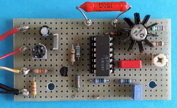
The purpose of this project is to provide a 4-20 mA output from a PWM signal generated by a microcontroller ATmega328 and numerous other chips, such as the PIC. One of the more interesting applications of this circuit would be to replace or to realize a smart sensor with Arduino.”
Sun tracker systems are widely used in solar panel setups to get maximum performance. You may want to use one in your personal solar panel setup. Now you can make your own with an Arduino, following the project that’s designed by RobotGeek Team and Wade Filewich.
Place the light sensors in correct position and wire them to Arduino accordingly. Any wrong positioning can generate strange behavior of the system. Jumpers for the servos (pin 9, 10, and 11) are set to VIN, so that your servos function properly.
(NOTE: A 6V power supply will work just fine, and RoboTurret Kit includes one). Here is the chart of wiring:
Wiring chart of servo,light sensor, potentiometer and Arduino : Sun tracker
There are two potentiometers. One is for controlling the speed of servos, and another is for controlling the sensitivity of sensors.
Set Up The Turret:
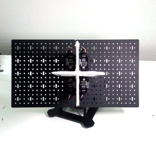
You should follow Desktop RoboTurret Assembly Guide to build the turret. After building, attach your sensors to the top plates as close to center as possible. Look at the picture:
Sensor Positions On Turret
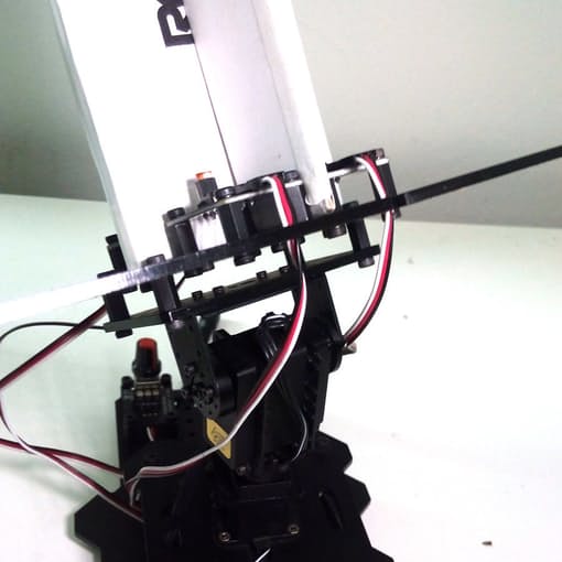
The “+” shaped fins cast shadow on sensors. So, position of sensors should be correct else fins can’t cast shadow on them accurately. Have a close view on sensor’s position:
Sensor position on turret : close view
While wiring through the plate, keep wires loose enough so that turret can move freely to aim at the Sun. At the back of the turret base, there is plenty of room to mount the two potentiometers.
The fins are 8 inches tall, which should be plenty to cast shadow on the sensors. I’ve used scrap cardboard for the fins, but you can use whatever material suits you best, so long as it is opaque and can throw a shadow.
Test It:
So, you finished the building process. Now let’s test it. Upload the code to Arduino and power up the system. Now hold a table lamp and move it. The turret should follow the movement. Adjust speed and sensitivity using the two potentiometers. Watch the video that demonstrates the system:
Google had launched Brillo, a new Android based OS used for embedded development – in particular for low-power, IoT devices. Brillo brings the simplicity and speed of software development to hardware for IoT with an embedded OS, core services, developer kit, and developer console.
Brillo works in conjunction with Weave, an open, standardized communications protocol that supports various discovery, provisioning, and authentication functions. Weave enables device setup, phone-to-device-to-cloud communication, and user interaction from mobile devices and the web. The chief benefit is allowing a “standardized” way for consumers to set up devices.
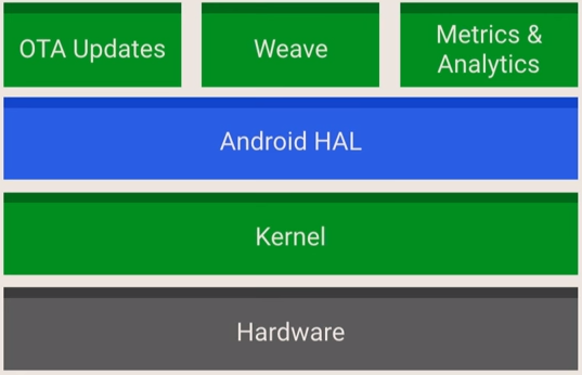
Brillo Structure
The big challenge is unifying and facilitating the communication among the estimated 200 billion smart devices expected by 2020. Whether you’re looking to build a simple DIY project or implement an enterprise scale m2m (machine to machine) project, Google’s new tools will be a big help. Fortunately, Brillo appears pretty easy for developers who are already familiar with Android.
Check this video by Google about Brillo and its features, and you can watch another video about Weave
Brillo supports a trio of ARM, Intel, and MIPS hacker SBCs (Single Board Computers) called “ made for Brillo” hardware kits. One of these kits is The Edison kit for Brillo by Intel, that includes an Edison IoT module plugged into a baseboard that offers convenient, Arduino-style expansion compatibility.
Edison for Brillo SBC
One of the great things about Brillo that the security issue with IoT applications is solved by choosing to use secure boot and signed over-the-air updates and providing timely patches at the OS level.
If you are interested in developing Brillo itself you can check the Brillo developer portal where code, development tools, and documentation for the Android-based Brillo embedded OS for Internet of Things devices can obtained. You should ask for an invitation then when you gain access you will get everything needed for your next project.
A high introduction was presented by Intel in the Open IoT Summit in April 2016, you can check it here.
As Intel, UN and IDC mentioned in their joint report that there will be an average of 26 smart devices for every human in just 5 years, we can predict a rapid growing development and enhancements for IoT systems, devices and protocols.
Ham radio is the use of radio frequency spectrum for purposes of non-commercial exchange of messages, wireless experimentation, self-training, etc. Developing a ham radio project may requires using an antenna analyser, a device that is used for measuring input frequency and impedance.
There are many types of antenna analysers such as Anritsu VNA Master, RigExpert, MiniVNA, and others. But these analysers are very expensive to buy. They starts from $500 up to thousands of dollars and they are also hard to hack. This guide shows how to construct and use a DIY HF antenna analyzer using Arduino for less than $50.
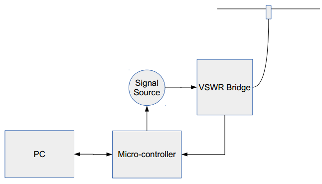
The project consists of three parts; a Microcontroller, AD9850 DDS module, and a VSWR Bridge.
Block Diagram
The AD9850 is a CMOS highly integrated device that uses advanced Direct Digital Synthesis (DDS) technology coupled with an internal high speed, high performance, D/A converter and comparator, to form a complete digitally programmable frequency synthesizer and clock generator function.
AD9850 module is a $9 stable, low drift VFO (Variable Frequency Oscillator) fed by a 125 MHz crystal clock. The module covers from 0 to 40 MHz, which are all the HAM HF(High Frequency) frequencies. There are 4 output pins on the device, 2 for Sine Waves (only one Frequency at a time) and two Square wave outputs. The blue pot on the board adjusts the duty cycle of the Square Wave Outputs but has no effect on the Sine Wave Outputs.
AD9850 features:
Signal Frequency output range: 0-40MHz
4 Signal outputs; 2 sine wave outputs and 2 square wave outputs
DAC SFDR > 50 dB @ 40 MHz AOUT
32-Bit Frequency Tuning Word
Simplified Control Interface: Parallel Byte or Serial Loading Format
Phase Modulation Capability
+3.3 V or +5 V Single Supply Operation
Low Power: 380 mW @ 125 MHz (+5 V)
Low Power: 155 mW @ 110 MHz (+3.3 V)
Power-Down Function
AD9850 Pin Definition
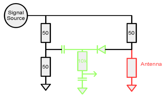
The VSWR (voltage standing wave ratio) bridge is an impedance bridge circuit, which is used to measure the ratio of maximum voltage (Vf+Vr ) to the minimum voltage (Vf-Vr) on a transmission line. The bridge will balanced (0 volts across the detector) only when the test impedance exactly matches the reference impedance. This bridge is easy and cheap to implement and works with up to few GHz frequencies.
VSWR Bridge Diagram
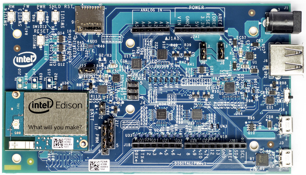
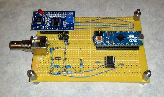
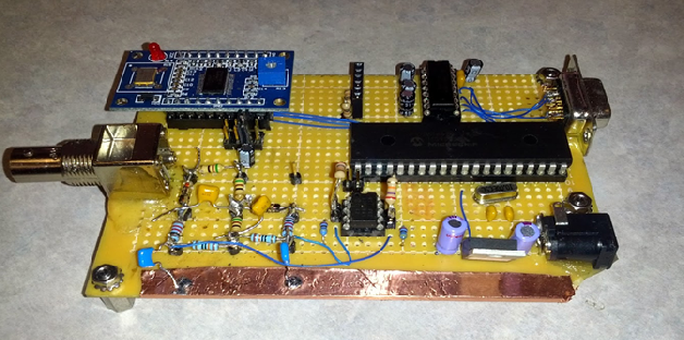
The microcontroller works as an interface between the DDS and the PC, it receives the sweep parameters from PC, and then it reads the collected voltage and frequency to the PC for each sweep. There are multiple choices about the microcontroller type, you can use either Arduino Micro or PIC. If you choose Arduino, the cost of the project will be around $50, while the cost will be reduced to $20 when using PIC.
Arduino SolutionPIC Solution
To display the results which are collected from the device, you need to develop a simple software and run it on the connected PC. The software GUI contains configuration buttons on the right side and 2-axis plane, which will hold the signal shape, on the left side.
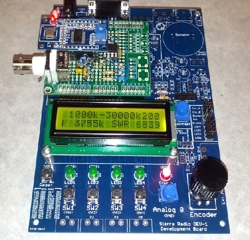
If you want to make the project portable, you can replace the PC with a LCD display to show the collected data.
This project is open source, you can find and download schematics and code from here. You also can apply your ideas to enhance the project, such as amplifying power for accurate VSWR, adding bluetooth connection to use with tablet, increasing supported frequencies range, and more.
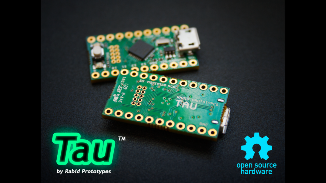
“Tau” is a new board in the world of embedded systems, designed by Rabid Prototypes. It is powered by a 32-bit ARM core, but Tau’s main strength is full compatibility with the well-known Arduino Zero, yet in a very tiny package.
The Tau!
What is the Tau?
The Tau is an extremely affordable, open source, miniaturized version of the Arduino Zero. It has 32bit ARM processor clocked at 48MHz, and boasting 16K of RAM. The Tau is far more powerful than standard Arduino.
Finally, being open-source, you’re free to modify it as you wish and integrate it into your own designs – without ever needing to pay any royalties or licensing fees!
Technical Details:
Microcontroller: Atmel ATSAMD21E17A ARM Cortex M0+
Like most Arduinos, the Tau features a few LEDs. A green LED lets you know that the Tau is receiving power, while a red LED is connected to pin 26 aka PIN_LED_TXL. This LED can be used as a status indicator.
While I could have connected the red LED to pin 13, which is the usual pin for a status LED on an Arduino, connecting it to pin 26 avoided the need to isolate it from the SPI bus with a mosfet, and left room for the power LED!
10-bit DAC
No more need to use Tone() command! Turn Tau into a music player by connecting an amplifier between pin A0 and the GND pad and use the Audio library to play .WAV files from a MicroSD card!
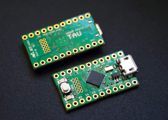
Tau 32 bit
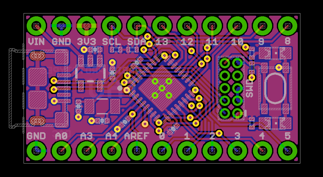
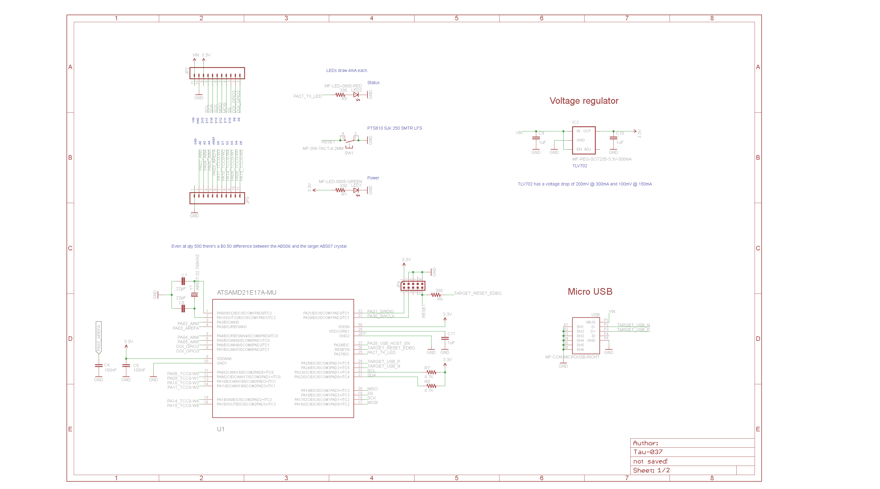
PCB And Schematics:
Tau PCBTau schematic
Installation:
To make the Tau work with the Arduino IDE, open the File menu and select Preferences. Then, in the Additional Boards Manager URLs section, place a comma after the last entry, and add the following link:
Once done, open the boards manager, which is on the Tools->Boards menu, scroll down to Rabid Prototypes, select the entry, and hit Install.
Finally go back to Tools->Boards, scroll down to the bottom of the list, and pick the Tau/Firecricket.
Once done, you should be ready to program the board.
Troubleshooting:
If you are unable to program the board, first make sure you’ve selected the correct board on the Boards menu. Then check if you’ve selected correct port on the Ports menu.
If that doesn’t work, try double clicking theReset button on the board. That forces the bootloader to be loaded instead of entering your sketch, which may be stuck in a loop where it is unable to check the USB port for connection.
Conclusion:
The Tau is a good alternative of Arduino Zero for its really tiny form factor and cheap price. It’s less than half of Arduino Zero’s price!
Three-axis MEMS accelerometers, Analog Devices’ ADXL354 and ADXL355 perform high-resolution vibration measurement to enable the early detection of structural defects via wireless sensor networks. The low power consumption of the devices lengthens battery life and reduces the time between battery changes. by Susan Nordyk @ edn.com
The analog-output ADXL354 and digital-output ADXL355 offer selectable measurement ranges of ±2 g to ±8 g and low 0-g offset drift. Both accelerometers provide guaranteed temperature stability with null offset coefficients of 0.15 mg/°C maximum. The ADXL354 boasts ultralow noise density (all axes) of 20 µg/√Hz and current consumption of just 150 µA in measurement mode. The ADXL355 has a noise density of 25 µg/√Hz and current consumption of 200 µA in measurement mode. Standby-mode current consumption is just 21 µA for each device.
Geiger counters are devices used to detect radioactive emissions, most commonly beta particles and gamma rays. The counter consists of a tube filled with an inert gas that becomes conductive of electricity when it is impacted by a high-energy particle.
The Geiger–Müller tube or G–M tube is the sensing element of the Geiger counter instrument used for the detection of ionizing radiation.
Biemster wanted to improve this counter to an IoT device connected to the network byusing ESP8266 to discover easily where are the harmful radioactive things around.
Geiger-Müller tube
Running down the center of the tube there’s a thin metal wire made of tungsten. The wire is connected to a high, positive voltage so there’s a strong electric field between it and the outside tube.
When radiation enters the tube, it causes ionization, splitting gas molecules into ions and electrons. The electrons, being negatively charged, are instantly attracted by the high-voltage positive wire and as they zoom through the tube collide with more gas molecules and produce further ionization. The result is that lots of electrons suddenly arrive at the wire, producing a pulse of electricity that can be measured on a meter, and if the counter is connected to buzzer heard as a “click.” The ions and electrons are quickly absorbed among the billions of gas molecules in the tube so the counter effectively resets itself in a fraction of a second, ready to detect more radiation.
In a nutshell, driving a G-M tube typically consists of 2 distinct parts:
Providing the tube with a high voltage source for it to operate.
Detecting each ionization event and convert it to a format that can be processed and sent over the internet.
Generating high voltage can be done by using PWM (Pulse-Width Modulation) signals after flashing the ESP8266 with the MicroPython firmware (version 1.8.3, with 10 kHz PWM support). Detection can be implemented as an interrupt handler that listens for and acts on discharges in the tube. Each discharge means a new detection.
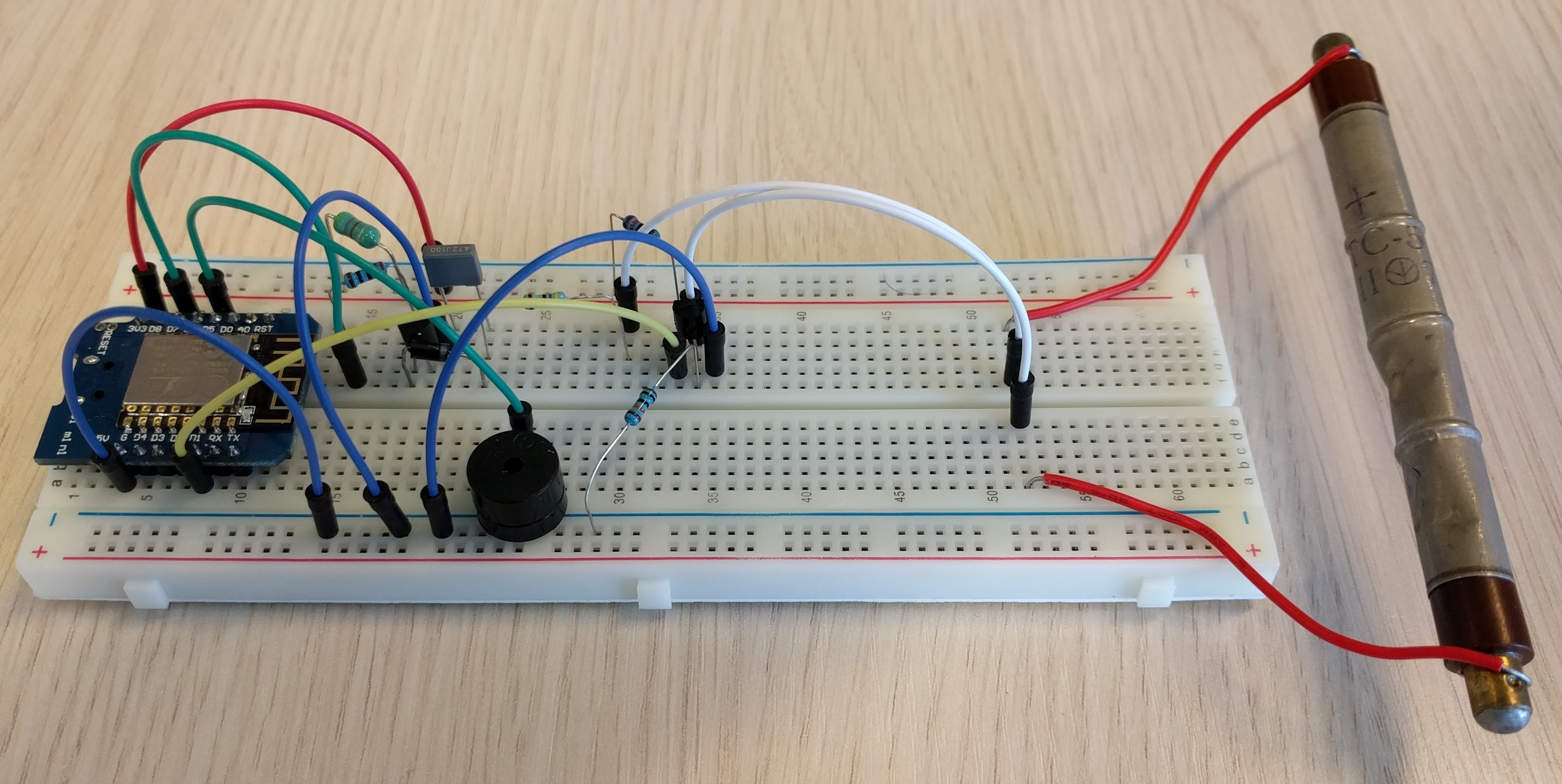
You will need the following components:
1x ESP8266
1x STS-5 Geiger tube
1x 4.7 mH inductor
1x 4.7 nF Capacitor
1x KSP44 transistor
1x 2N3904 transistor
1x 1N4007 diode
1x 4.7M resistor
1x 100k resistor
1x 10k resistor
1x 220 ohm resistor
1x optional piezo buzzer
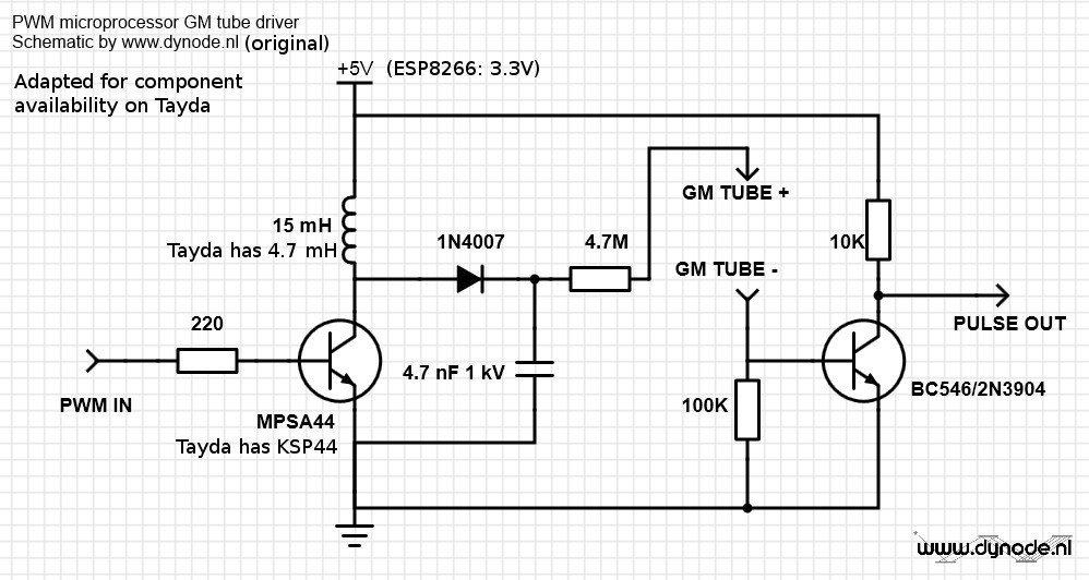
Circuit Schematic
The circuit works as follows: A ~1 Khz squarewave turns the MPSA44 high voltage transistor on and off, generating high voltage when the inductors current is shut off. The voltage depends on the pulse width of the square wave which can be tweaked in software. The 1N4007 diode rectifies this voltage, and the High-Voltage capacitor removes most of the ripple on this voltage. The resistor limits current to the G-M tube. The current pulses from the tube generate a voltage drop over the 100K resistor which turns on the BC546. When this happens the voltage through the 10K resistor is pulled to ground, generating a negative going pulse each time the G-M tube detects an ionizing ray or particle.
The code reports every event over MQTT, the lightweight IoT protocol. It also reports the CPM (Counts per Minute) and the time passed since the previous event as (CPM,dt). The library of this project is available at Github, It handles the low level stuff such as PWM and pin assignments, and a general part that will communicate the measurements out to the world.
For more details, build instructions, and project updates you can follow the project on hackday.
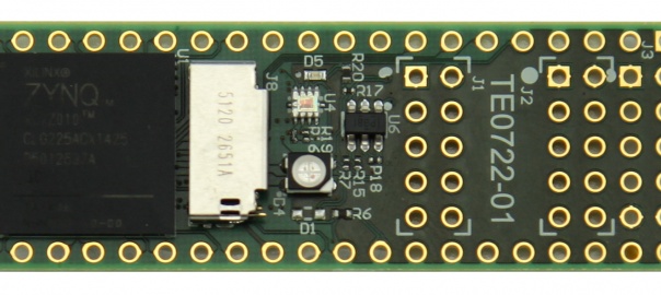
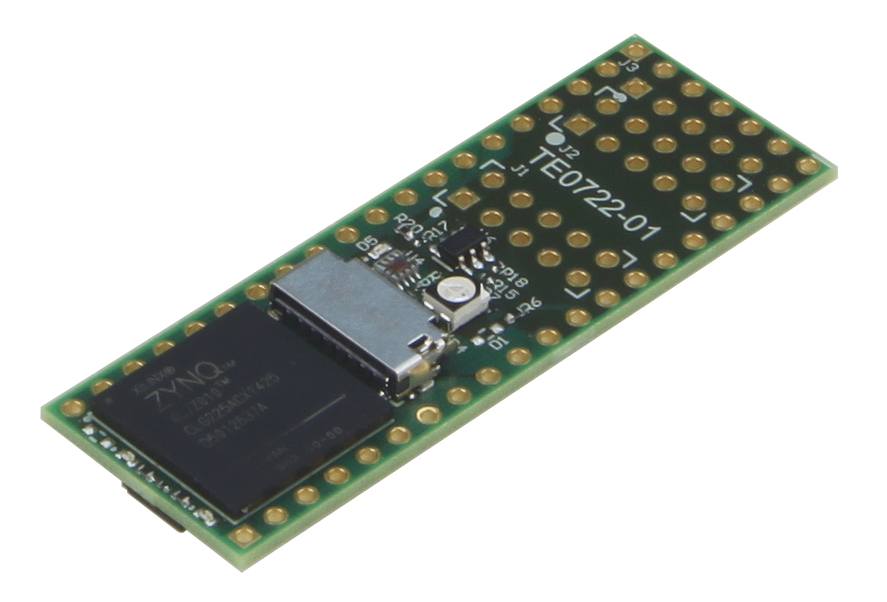
The DIPFORTy1 is a powerful Xilinx based FPGA board with small form factor and many programmable I/Os. It is popular for its high performance at most competitive price.
DIPFORTy front face
Introduction:
The TE0722 is based on the Xilinx Zynq-7000, a System on Chip. It contains a FPGA and a Dual Core ARM A9+ processor with enough logic gates to become a Propeller. The board also has 16 MByte of flash used for configuration. Everything fits on a Propeller-compatible DIP 40 pin board. The 16 MByte storage space is good enough for primary boot, though a micro-SD card can be attached as MIO/ZYNQ secondary boot media.
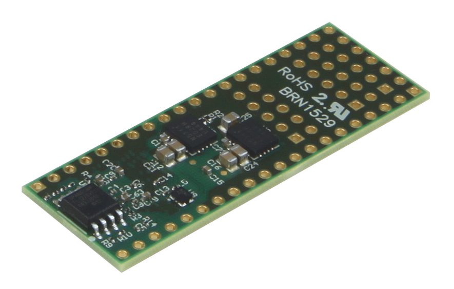
DIPFORTy back side
The DIPFORTy1 ‘Soft Propeller’ is the lowest cost Zynq based module ever made. It’s also the first Zynq module that can use existing bases and project boards (Parallax Propeller chip compatibility). All this in a compact 1.8 x 5.1 cm form factor, at the most competitive price.
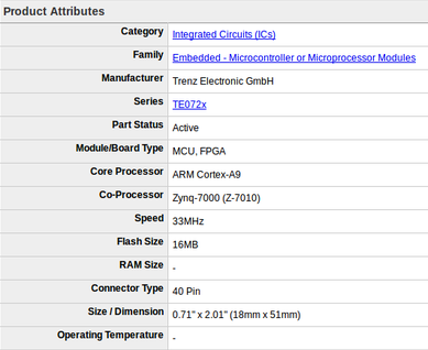
Quick look at specs:
DIPFORTy1 quick specs
About FPGA:
It’s good to have some knowledge about FPGA before getting to know about DIPFORTy.
field-programmable gate array (FPGA) is an integrated circuit designed to be configured by a designer after manufacturing. The FPGA configuration is generally specified using a hardware description language (HDL), similar to that used for an application-specific integrated circuit (ASIC).
FPGAs contain an array of programmable logic blocks. The hierarchy of configurable interconnects allows the blocks to be “wired together”. It’s just like many logic gates that can be inter-wired in different configurations. Logic blocks can be configured to perform complex time-independent logics. Blocks also can perform merely simple logic gates like AND and XOR. In most FPGAs, logic blocks also include memory elements. It can be simple flip-flops or more complete blocks of memory.
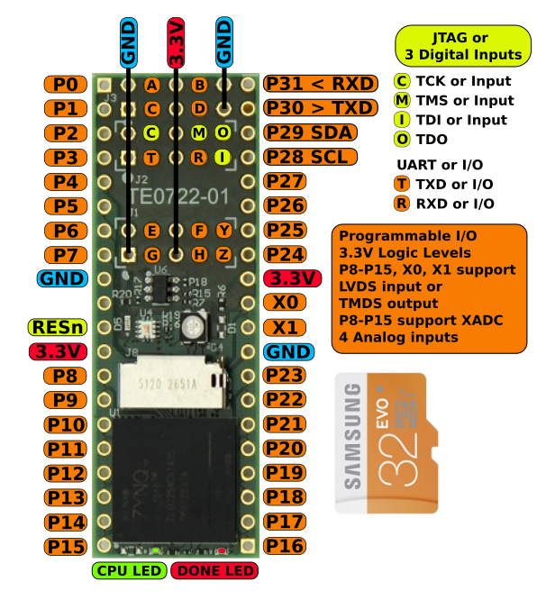
Features of TE07722 DIPFORTy1:
The DIPFORTy1 has lots of features. Lets have a look:
The FPGA board is designed using Xilinx ZYNQ-7: XC7Z010-CLG225.
zynq-mp-core-dual
Zynq-7000 devices are equipped with dual-core ARM Cortex-A9 processors integrated with 28nm Artix-7 or Kintex®-7 based programmable logic for excellent performance-per-watt and maximum design flexibility. With up to 6.6M logic cells and offered with transceivers ranging from 6.25Gb/s to 12.5Gb/s, Zynq-7000 devices enable highly differentiated designs for a wide range of embedded applications.
Conclusion:
As the DIPFORTy1 is an industrial-grade Zynq-7000 SoC module, it’s highly powerful and appropriate for wide range of embedded applications including multi-camera drivers assistance systems and 4K/2K Ultra-HDTV. The board is totally value for money.
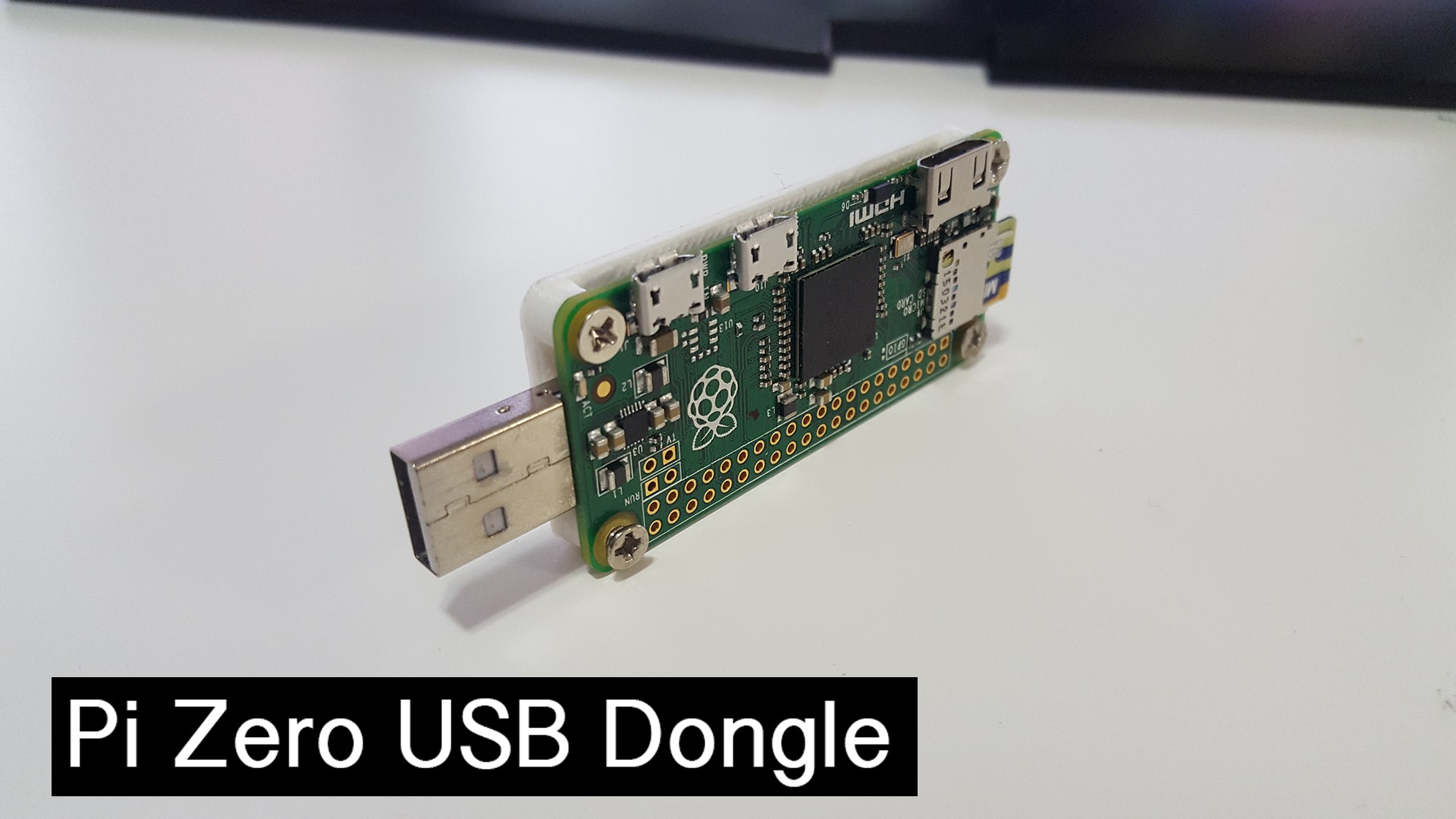
The $5 Raspberry Pi Zero is a standalone computer that can be embedded in various applications, but maybe now it is time to add some extra features.
It comes with a USB OTG port, meaning it can function as a USB device rather than a USB host. Thus, it can become a serial device with just a USB cable, an Ethernet device, MIDI device, camera, or just about anything else you can plug into a USB port.
Novaspirit has turned his Raspberry Pi Zero into a USB gadget, just like a RNDIS modem, with some easy steps. He aims to get the maximum benefit out of a Pi Zero without having to lug around any cables: “Just plug it in and you’re networked”
His hack turned the Zero Pi into a USB dongle with shared internet, and he could install services like webmin, owncloud, and vnc making it a great all-in-one device!
With minimal soldering, he converted the Zero’s onboard female USB jacks into a male USB plug.
You only need:
male usb connector
4 wires
some soldering skills
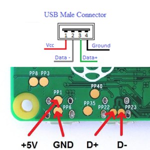
Then you can follow the diagram to connect the male connector to Zero Pi
How to ‘donglify’ the Raspberry Zero Pi as Novaspirit suggests
Attach the Raspberry Pi Zero running Pixel OS to your computer as a USB network device
Set up VNC (Virtual Network Computing) on the Pi so that you can log into its desktop in a window
Set up networking on the Pi so that it can connect to the wider Internet through the laptop
Install OwnCloud so that the Zero serves as a cloud storage
Check out this tutorial by Novaspirit
Novaspirit guy is not the first who converted the Raspberry Pi Zero into a USB gadget that connects to the internet, but the most interesting thing about his project that you won’t lose any functionality of you Zero Pi; you can still plug your stuff and use it in your applications. In addition, he delivered a very simple hardware hack and easy to follow software tutorial on Windows.
You can check his website Novaspirit for weekly posts where you can find loads of projects and tutorials.
More details, designs and code snippets of this project can be reached here.
Sometimes the float valve of a water tank may not work properly causing water to overflow and spread across the floor. Peter Jennings faced this problem in his storage area, and he had developed an alarm device to notify him when the water exceeds its normal range.
Peter’s project includes a simple water sensor and ESP8266 wifi module connected with power switch circuit. When the water reach a specific threshold, the sensor will trig the switch to turn on the ESP8266, which will connect to a wireless network and send a message to a web server.
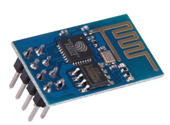
ESP8266 is a wifi module contains System-On-Chip (SOC) with integrated TCP/IP protocol stack that can give any microcontroller access to any WiFi network. The ESP8266 is capable of either hosting an application or offloading all Wi-Fi networking functions from another application processor. There are various versions of ESP8266 differ in size, shape and price. Peter used this $1.5 module, and you you are free in choosing your ESP8266 board.
ESP8266 ESP-01 Board
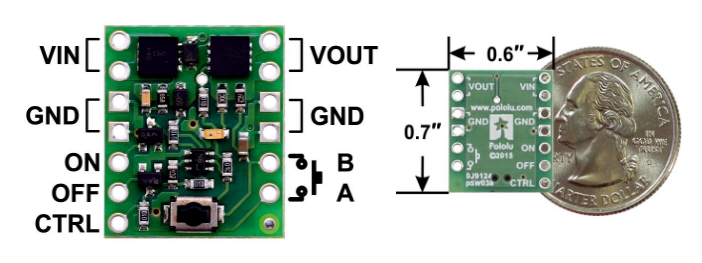
Mini Pushbutton Power Switch from Pololu, an electronics manufacturer and an online retailer, is the power switch circuit used in this project. It is a $4 power control alternative to bulky mechanical switches which is able to turn on and off any device using the mini push button on the board, the external on & off pins, or a control signal. This low-voltage version operates from 2.2 V to 20 V and can deliver continuous currents up to around 6 A.
Mini Pushbutton Power Switch Board and Dimensions
The sensor which is used to detect the overflow is very simple, it is just two wires pinned inside the tank above the highest level that water should reach. One of these wires is connected t
o the Vin pin, and the other is connected to CTRL pin on the switch circuit. DC current will flow between the two wires when the water pass the limit sending a control signal to turn on the Wifi module.
This combination is powered by a range of 3 volts to 3.6 volts battery pack. The circuits should be connected as shown in the diagram:
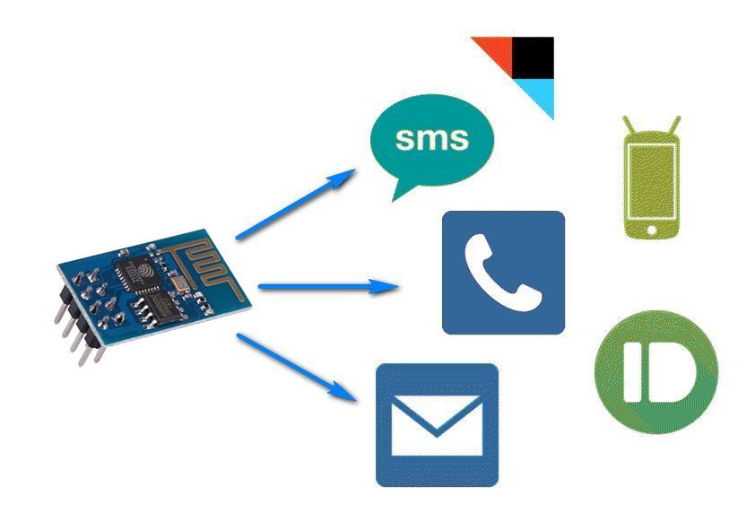
You have to create your own web server which will receive the message from the ESP8266 and notify you. If you are not familiar with web development you can use IFTTT, a free web-based service that allows users to create chains of simple conditional statements which are triggered based on changes to other web services.
To use IFTTT, you have to create your own account, then proceed to the Maker Channel to create a Trigger event. IFTTT will give you the URL to enter into the ESP8266 code. You can set the alarm to run a ringtone on your android device, tweet on your twitter account, post in facebook, send an email, and a lot of other choices.
There are also many ways to program the ESP8266. Peter used the simple NodeMCU Lua system, but for Arduino fans there is an Arduino firmware installation available for the ESP8266 which can also be used to implement the simple firmware required.


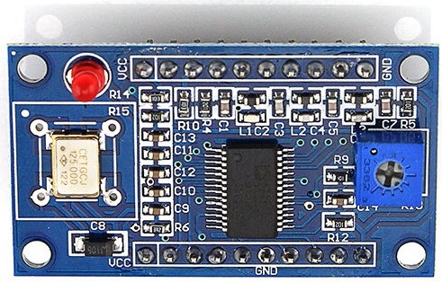 AD9850 module
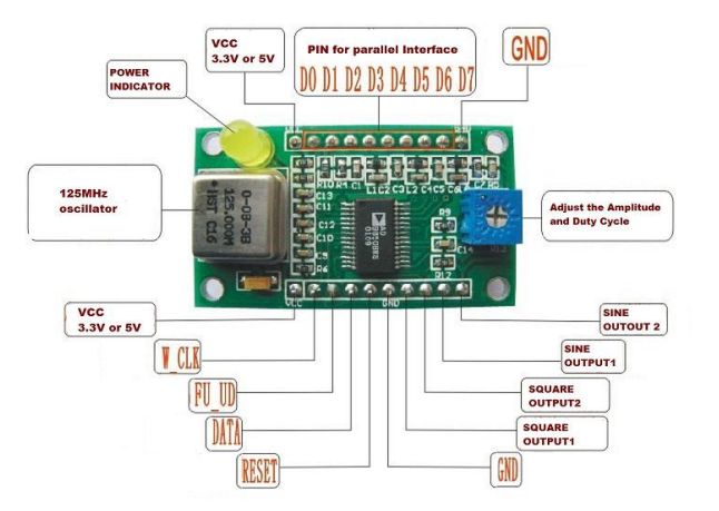


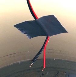 The sensor which is used to detect the overflow is very simple, it is just two wires pinned inside the tank above the highest level that water should reach. One of these wires is connected t
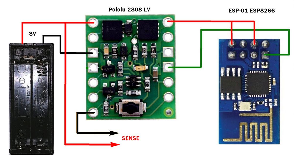