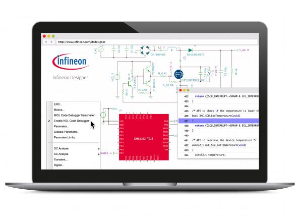
Infineon Technologies’ Infineon Designer, introduced at the 2016 electronica trade fair, is presented as the first online prototyping engine combining analogue and digital simulation functionalities in an internet application. By Graham Prophet@ edn.com:
Requiring a web browser only, it is an aid to designers in selecting the right product for a defined application. Infineon Designer works intuitively in a very short time, and neither installation nor licenses are needed. The program features application circuits in the domain of Industrial Power, Lighting, Motor Control and Mobile/RF frontend design. It enables analogue/digital co-simulation of the 32-bit XMC1000 industrial microcontroller ARM Cortex-M0 series, using the free-of-charge code generation platform DAVE.
Online prototyping with A/D simulation, in Infineon Designer – [Link]
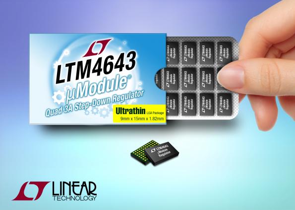
Configurable as quad, triple, dual or single output, the LTM4643 quad output step-down µModule [micromodule] (power module) regulator deliver, respectively, 12A, 6A & 6A or 9A & 3A, or 4 x 3A from a 9 x 15 x 1.82 mm ultrathin LGA package. by Graham Prophet @ edn.com:
This flexibility enables system designers to rely on one simple and compact µModule regulator for a variety of voltage and load current requirements in FPGA, GPU, ASIC and processor-based applications. The 1.82 mm height ultrathin package allows the LTM4643 to be mounted on the backside of the PCB, freeing space on the topside. The LTM4643 is suitable for systems with height restrictions, such as backside PCB assembly in PCIe applications and where the regulator must fit under a common heat sink or cold plate to cool high power FPGAs, GPUs, ASICs and processors in applications such as embedded computing, data storage, medical imaging and industrial systems
Typical pro-mini loggers built with this design sleep at 0.25mA, before extra sensors are added. At that current draw, the logger should deliver approximately six months of operation on three brand new AA batteries with a 15min duty cycle; depending on sensor load.
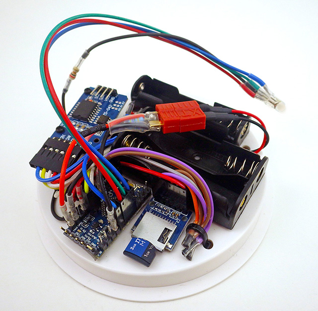
Lucky Resistor has build a PWM fan controller using Arduino and DHT22 sesnsors.
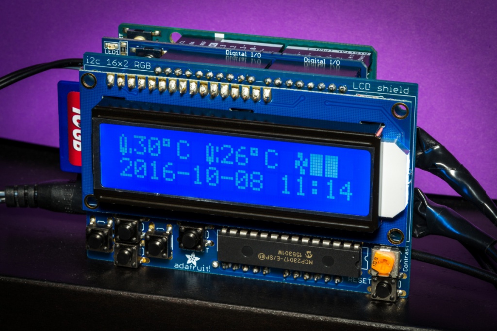
The fan controller described on this project page, controls one or more PWM controlled 12V PC fans. It uses the input from two precise DHT22 based temperature sensors. The MCU is an Arduino Uno, which is powered using a 12V power source. On top of the Arduino Uno, there is the Adafruit data logger shield — and on top of that is an Adafruit LCD shield. The software is a simple, custom written PID controller.
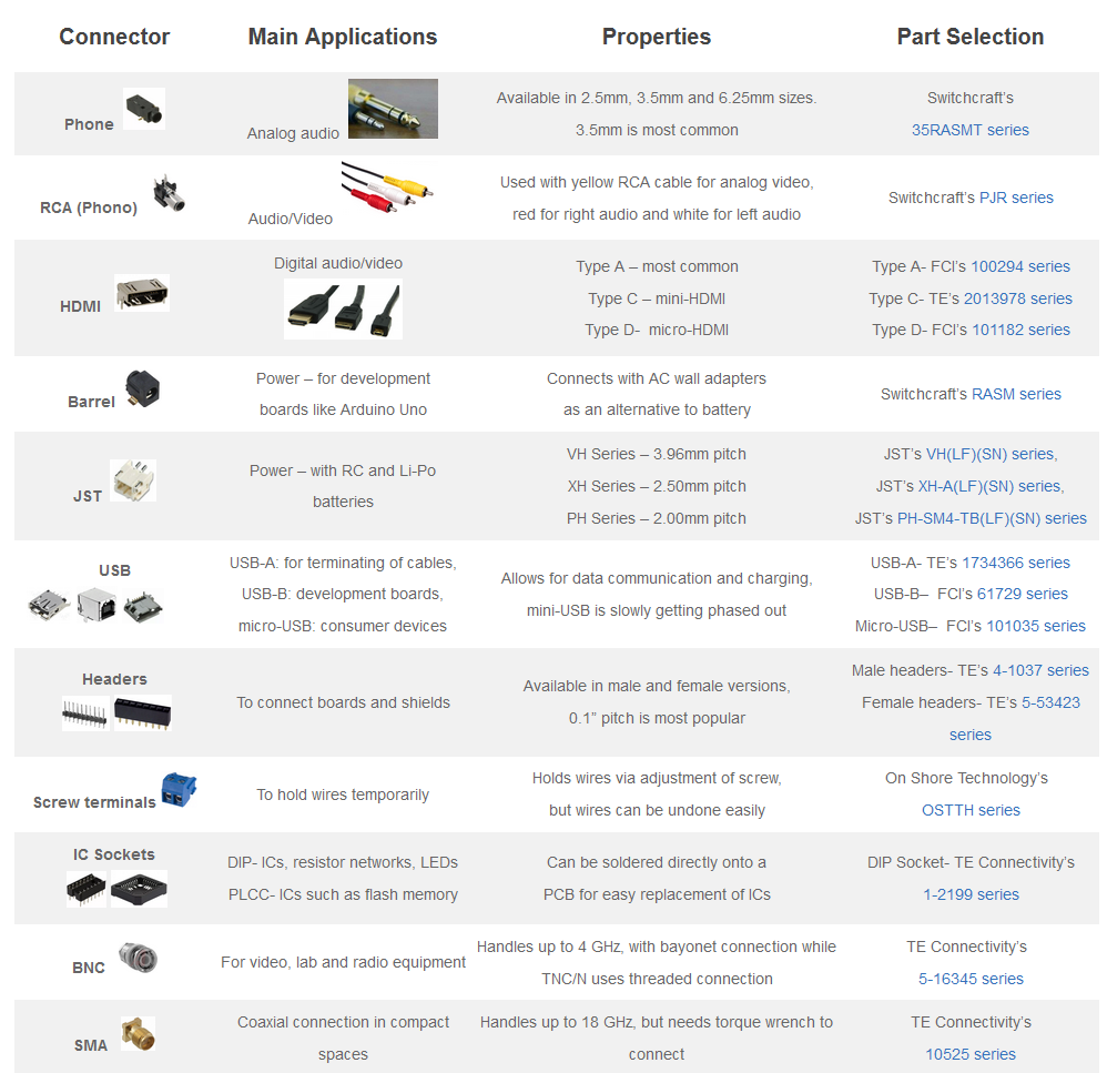
Sanket Gupta @ octopart.com discuss on how to choose a connector. He writes:
Continuing our series about choosing parts, inspired by the latest version of the Common Parts Library, let’s take a close look at how to find and select connectors. In this blog, we will explain all the different types of connectors, their merits and demerits, and their popular applications. We will also recommend some commonly used connectors with high supply chain availability to help you find the right connector.
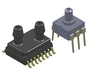
These micropower low-pressure sensors operate from a supply voltage of just 0.9 V to 1.8 V and are intended for use with noncorrosive, nonionic working fluids in such applications as medical devices and instrumentation, environmental controls, HVAC equipment, and portable devices.
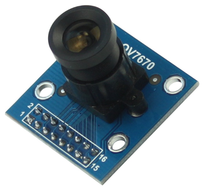
Developing a hardware project became much easier thanks to the growing number of the various sensors and actuators modules, which give you the ability to shift your ideas into a wider range of applications. This tutorial presents the steps of how to use OV7670 Camera Sensor Module STM32 with Arduino.
To follow the tutorial, you will need these parts:
Arduino Uno Board and USB
OV7670 Arduino Camera Sensor Module STM32
Resistor (2x10K & 2×4.7K)
Breadboard
The OV7670 image sensor is a small size, low voltage, single-chip VGA camera and CMOS image processor for all functions. It provides full-frame, sub-sampled or windowed 8-bit images in various formats, controlled through the Serial Camera Control Bus (SCCB) interface.
The camera module is powered from a single +3.3V power supply, and external clock source for camera module XCLK pin. The OV7670 camera module built-in onboard LDO regulator only requires single 3.3V power and can be used in Arduino, STM32, Chipkit, ARM, DSP, FPGA and etc.
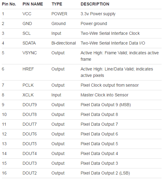
This is pin definition table of the module:
OV7670 Pin Definition
OV7670 module specification:
Optical size 1/6 inch
Resolution 640×480 VGA
Onboard regulator, only single 3.3V supply needed
Mounted with high quality F1.8 / 6mm lens
High sensitivity for low-light operation
VarioPixel® method for sub-sampling
Automatic image control functions including: Automatic
Exposure Control (AEC), Automatic Gain Control (AGC), Automatic White Balance (AWB), Automatic
Band Filter (ABF), and Automatic Black-Level Calibration (ABLC)
Image quality controls including color saturation, hue, gamma, sharpness (edge enhancement), and anti-blooming
ISP includes noise reduction and defect correction
Supports LED and flash strobe mode
Supports scaling
Lens shading correction
Flicker (50/60 Hz) auto detection
Saturation level auto adjust (UV adjust)
Edge enhancement level auto adjust
De-noise level auto adjust
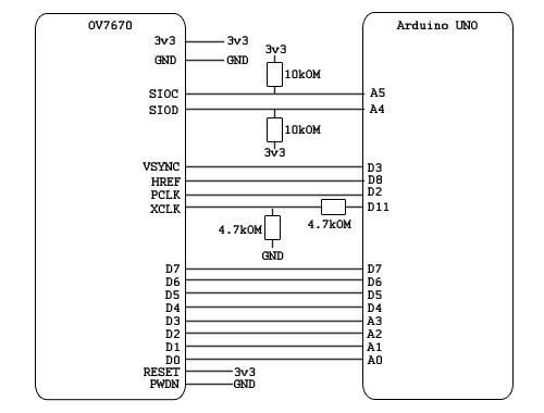
The connection between the module and the Arduino uses 6 analog pins and 8 digital pins, and they have to be connected as shown in this figure:
The software requirements are the Arduino IDE and Java Development Kit (JDK). To run the project, you have to execute a java code through the command line. The script will search for images received from Arduino and then saves them on the PC.
Source code, additional needed files, and setting up instructions are all available at the tutorial page.
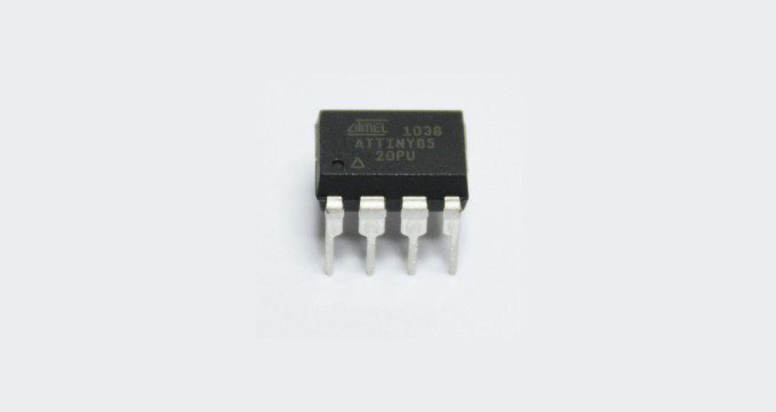
Hi! Today I’ll explain you how to recover your bricked ATtiny microcontroller using your Arduino board. ATtinys are very popular due to their small form factor yet very powerful. While working with them you may accidentally brick the ATtiny. As arduino is extremely popular and really easy to use, I guess you have one or more lying on your work table. You don’t need to purchase a HVP (High Voltage Programmer), or search for an old PC with parallel port to recover ATtiny. Just build a small circuit, plug it into Arduino board, upload a sketch and you are good to go. So let’s start… Continue reading “Recover Bricked ATtiny Using Arduino as high voltage programmer”
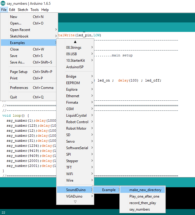
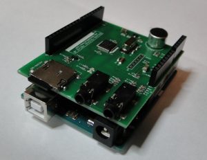
The electronics engineer and microcontroller programmer expert, Masih Vahida has launched his latest SoundDuino Arduino shield product: SoundDuino 3!
SoundDuino is a WAV Sound Player & Recorder Shield for Arduino. This sound shield let you record and play sound files to or from a Micro-SD memory card with all libraries and samples for the Arduino IDE.
“SoundDuino is a sound recorder and player that is able to play the sound files from the Micro-SD memory card or even record sounds to the memory with your desired file name. It supports FAT16 and FAT32 and you can easily copy your files into the memory and to play them, you only need to use the library that we give you with this shield and just send the file name that you want to play! Yes, very very easy!” Vahida explains.
This video shows the very first version of SoundDuino and some of its applications
The newest shield, SoundDuino3, is based on NXP LPC2103 ARM7 32bit microcontroller and it can play 16 bit 48khz sound files with a very high quality. It also has audio input and output jacks, an onboard microphone as well and can work from 3.3v to 5v. SoundDuino fits nicely on an Arduino Uno and is compatible with any Arduino boards using pins GND, VCC, RX and TX. Moreover, the device is delivered with libraries and examples for Arduino IDE.
This project is now live on Kickstarter, check the campaign video
You can use this shield to announce numbers and add you own files into the memory. You can also extend the example code and have it read the text also.
SoundDuino 3 specifications:
Updated firmware, high quality audio
Automatic baudrate detection
Sound quality is Stereo 16 bit 48hkz (SoundDuino 1 was Mono 8 bit 48khz)
Super easy to use, new functions in library to announce the numbers .
More useful functions in the library
the sound quality is much much better than the last version
Small size
System voltage is 3.3v compatible with Arduino boards
With SoundDuino shield it seems easier to start building some great audio projects. You can follow the project updates and order your own SoundDuino 3 for $59 now from the crowdfunding campaign.
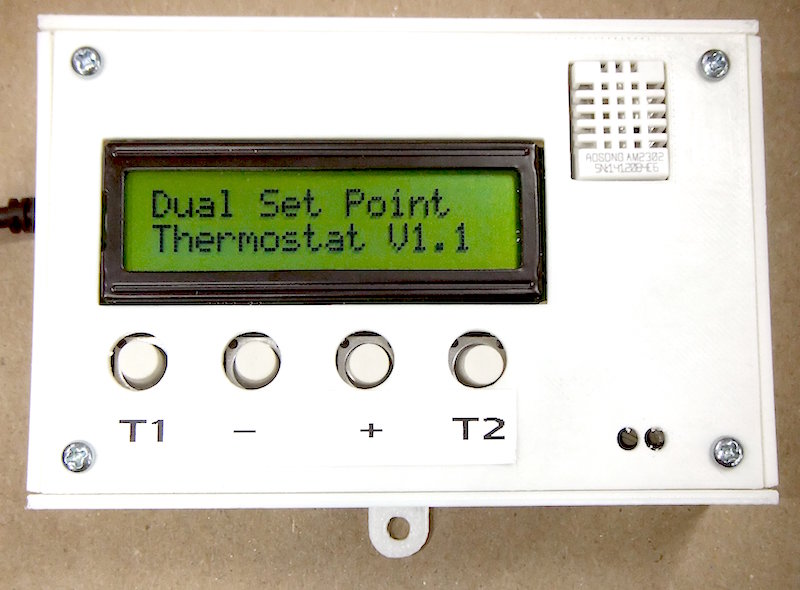
Programmable thermostats are cool things. They let you set the room temperature according to your schedule and will automatically make those adjustments for you. If you use them the way they’re intended to, they could be a great way to save on home energy costs. They work perfectly for people with fixed daily schedules. You can set one temperature during the time you are at home and to another when you are away. But what if your everyday routine is not the same? Then you have to manually adjust the temperature every time you are in and out. Ed Van Every was facing the same issue and he came up with a nice DIY solution for this. He wanted his place to be heated to 70ºF when it is occupied, and to 55ºF when it is not. So he made his own dual set point thermostat which allows him to implement his “working temp” with a single hit of a push button and his “away temp” with another push button.
DIY dual setpoint thermostat
Like most other DIY thermostats, Ed also used an Arduino board as the main brain of the thermostat and DHT22 for sensing ambient temperature and humidity. For controlling the heater, an electromechanical relay breakout board was used. A 16×2 character LCD displays the temperature setting that is currently active, its set-point value, the actual room temperature and humidity. In the event when the heater is turned on, an asterisk symbol * is displayed in the lower middle of the display indicating that the relay circuit is closed. The room temperature and humidity are refreshed every 2½ seconds and the LCD backlight automatically turns on for 60 seconds when a button is pressed on the thermostat. Ed also 3D printed a nice enclosure for his thermostat to give it a more professional look.


 The electronics engineer and microcontroller programmer expert,