The Tiniest 1nm Gate Transistor

A research team led by faculty scientist Ali Javey at Berkeley Lab have debuted the smallest transistor ever reported. A gate structure of just 1 nm long can bring Moore’s law back again after the demonstration of the recent Silicon (Si) transistor with 5 nm gate. It was predicted that transistors will fail below 5 nm gate because of some short channel effects that would change the transistor characteristics, but the new finding is proving that wrong.

1
Model showing the transistor structure


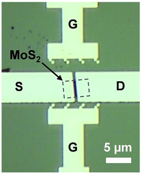
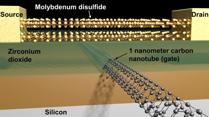
Because of current leakage that would happen in less than 5-nm Si transistors, the  exploration of new channel materials that have more ideal properties than Si should begin. The researchers used carbon nanotubes and molybdenum disulfide (MoS2), an engine lubricant commonly sold in auto parts shops. MoS2 is part of a family of materials with immense potential for applications in LEDs, lasers, nanoscale transistors, solar cells, and more. Fortunately, MoS2 electronics properties as thin layers will limit leakage that happen in Si alternatives.

While the researchers started using MoS2 as the semiconductor material, they recognized the hardship of constructing the gate using it.Thus, they turned to carbon nanotubes, hollow cylindrical tubes with diameters as small as 1 nanometer. This structure made it easier to control the flow of electrons effectively.

mos2
Optical image of a representative device shows the MoS2 flake, gate (G)

This project is just a proof of concept and researchers have not yet found a way to mass-produce it or integrate it in chips. They could break the myth of the Si transistor 5-nm gate limit and they paved the way for future researchers to demonstrate a new device architecture.

With such a small scale it will be an unexpected future of tiny devices that use lots of transistors, since all the technology we use nowadays are made of transistors with minimum 7nm geometry.

The work at Berkeley Lab was primarily funded by the Department of Energy’s Basic Energy Sciences program.

This research was introduced as a research paper in Science magazine on October 2016. More details are available here  “MoS2 transistors with 1-nanometer gate lengths“.

NEC Display Powered by Raspberry Pi

Earlier this month, NEC Display Solutions Europe announced that they are working on a new generation of large-format displays that support the Raspberry Pi compute module, enabling a seamless integration of Raspberry Pi devices with NEC displays.

2

Originally developed to promote the teaching of basic computer science in schools and developing countries, the first Raspberry Pi delivered good performance at a very low cost. However, the latest Raspberry Pi 3 compute module boasts significant performance and networking capabilities, making it perfect for NEC displays.

Raspberry Pi announced the compute module about two years ago, which is primarily designed for those who are going to create their own PCB. It is a small 67.6x30mm board that fits into the standard DDR2 SODIMM connector, with integrated BCM2835 quad-core 1.2GHz processor, 512MB of RAM, and 4GB eMMC Flash device. The board is no longer a basic computer for coding, but a reliable intelligent device with unlimited possibilities. In addition to the standard Raspberry Pi 3 compute module, NEC will also offer a customized model to meet the specific performance demands of the display industry.

untitled

“When we started Raspberry Pi, we had one main goal of helping people learn about computing and how to make things with computers. However, we’ve been fortunate enough to have sold 10 million Raspberry Pis so far and the commercial success has led to the third generation of a more mature and powerful technology which can be used with NEC’s intelligent display. Our work on the Raspberry Pi mini-computers is driven by the huge community of developers whilst NEC’s work is driven by industry needs, enabling us to meet the demands of the AV and IT industry. Overall, this collaboration shows NEC’s confidence with our ability to provide a platform that can be used in a variety of environments.” said Eben Upton, CEO at Raspberry Pi Trading.

The new NEC displays allow easy access to embedded intelligence smartly connected to Internet of Things (IoT) for digital signage as well as presentation use. The elegant design of the displays is suitable for smooth installations in any environment. There’s also the chance to customize the screens to individual needs, making the displays more reliable anywhere and anytime.

The displays will be available in January 2017 starting with 40″, 48″, and 55″ models and will eventually scale all the way up to a monstrous 98″ by the end of the year.

1

“Our strategic initiative to team up with Raspberry Pi is an example of how we continue to ensure that organisations in any sector have the most advanced technology in place to meet their application needs. Our open platform approach provides display intelligence at any time, thanks to our modular and interchangeable design. Integrating the Raspberry Pis with our displays will provide businesses with advanced technology suitable for digital signage, streaming and presenting to enhance the overall visual experience at an affordable price point,” said Stefanie Corinth, Senior Vice President Marketing and Business Development at NEC Display Solutions Europe GmbH.

In this video, Thomas Walter – the Head of Product Marketing at NEC, talking more about what’s going on behind the screens.

Layout software eases 3D prototype production

2016-10-24-eete-jh-beta

A manufacturer and service provider for PCB prototyping, Beta LAYOUT has developed a 3D MID CAD program to speed up the prototyping and small-series manufacturing of 3D Mechatronic Interconnect Devices (MIDs). by Julien Happich @ edn-europe.com:

Circuit carriers of the three-dimensional circuit boards are produced at Beta LAYOUT using 3D printing. This eliminates the need for costly injection moulding dies, as commonly used in series production. After this, the MID components are processed on a special production line using laser direct structuring, and then assembled.

Layout software eases 3D prototype production – [Link]

Thermal design: Get the heat out of the electronics

hausermann_hsmtec_pcb
Häusermann has a propriety process that makes PCBs that can conduct a great amount of heat or current.

@ edn.com discuss about thermal design in electronics and how to design your board to dissipate it effectively.

If you have high-powered LEDS, or a power supply, or are trying to control larger motors, you have to get a lot of heat out of your circuit boards. The classic way to dissipate heat is to bolt your power transistor to an aluminum heat sink. That is a slow, messy, and expensive proposition, especially if you need thermal grease between the transistor and heat sink.

[..]

It’s always a good idea to make thermal management inherent in your PCB design. Experience has shown you can get about 2W of heat out of a 3×5” copper area on a conventional FR4 PCB.

Thermal design: Get the heat out of the electronics – [Link]

PiOSCBOX: A Raspberry Pi based audio processor and synthesizer

Raspberry Pi carries a lot of horsepower inside to handle the realtime audio and add some effects to it. The only limitation is it does not have a built-in sound card, but it is manageable using an external USB soundcard. PiOSCBOX is an attempt to make a low-cost, stand-alone audio effects processor and synthesizer using Raspberry Pi 3. It provides a very nice and interactive user interface using a 128×64 graphic LCD and six rotary encoders. As with all other audio processors based on Raspberry Pi, PiOSCBOX also requires an external USB audio adapter.

Raspberry Pi based audio processor

The audio processing and synthesizing involves heavy Fast-Fourier transform computations and other DSP capabilities. PiOSCBox utilizes Pure Data for all of the DSP implementations. If you are unfamiliar with Pure Data, it is an open source visual programming language that allows musicians and artists to develop a software graphically (without writing a single line of code) to process and generate audio, video, and 2D/3D graphics along with interface external sensors and other input devices.

The software required for the PiOSCBox can be downloaded from the following location: https://github.com/star-fs/PiOSCBox

Once it is cloned to the /home/pi/PiOSCBox/ location on your Raspberry Pi, you need to run the build script, which will compile the rotary encoder components. The project also requires some external dependencies like WiringPI and Liblo, which are both embedded into NOOBS operating system for Pi.

$3.6 GPRS GSM Module from Ai Thinker

ShenZhen Ai-thinker CO.,a leading enterprise in the Internet of Things (IoT) industry and the maker of the ESP-12E module, had launched a new killer module: $3.60 GSM GPRS A6 Module!

Providing a chip cheaper than the popular ESP8266 seems to be promising and opens doors for future IoT inventions. This module seems to be a big competitor for SIM900 series module.

This chip is considered the cheapest platform that connects to the internet via GSM/GPRS and at the same time works as a traditional GSM module.

a6-ai-gsm-module-my-electronics-lab

a6-gsm-gprs-ai-thinker-breakout-board-with-antenaThis module is coming in market as a SMT package, like ESP12E, but there are many vendors already making breakout board with antenna out and SIM card slot, for an extra dollar.

Technical Specifications
  • Dimensions 22.8 × 16.8 × 2.5mm;
  • Working temperature -30 Celsius to + 80 Celsius;
  • Working voltage 3.3V-4.2V;
  • Power voltage> 3.4V;
  • Standby average current 3ma less;
  • Support GSM / GPRS four bands, including 850,900,1800,1900MHZ;
  • Support China Mobile and China Unicom’s 2G GSM network worldwide;
  • GPRS Class 10;
  • Sensitivity <-105;
  • SMT 42PIN
  • Support voice calls;
  • Support SMS text messaging; can use SMS to config module
  • Support GPRS data traffic, the maximum data rate, download 85.6Kbps, upload 42.8Kbps;
  • Supports standard GSM07.07,07.05 AT commands and extended commands;
  • Supports two serial ports, one serial port to download an AT command port;
  • AT command supports the standard AT and TCP / IP command interface;
  • Support digital audio and analog audio support HR, FR, EFR, AMR speech coding;
  • Support ROHS, FCC, CE, CTA certification;
  • Support up to 8 channels network connections
  • Low power consumption: standby least is 3mA
  • A6 semi-hole technology, enabling rapid production modules through standard SMT equipment, providing customers with highly reliable connection, especially for automation, large-scale, low-cost modernization of production methods.

It can be used with AT Commands like the commands for other GPRS/GSM modules SIM800/SIM900. Thus, it is possible to use the same libraries

How to use A6 GSM GPRS module:
  1. Connect UART_TXD to RX of the FTDI
  2. Connect UART_RXD to TX of the FTDI
  3. Connect GND to the GND of the FTDI
  4. Connect VCC5.0 To the PWR_KEY pin
  5. Connect a Micro Usb for the power(with any smartphone charger)
  6. After 4-5 second you can remove the connection between VCC5.0 and PWR_Key
A6 GSM GPRS Module Pinout

You can use it with the Arduino software, just choose a port and open the serial monitor with 115200 baud. To set up the connection send ”AT”, and if you see “OK” then everything works.

A project using the module, download the software, documents, and codes from here. Also watch a test demo.

The module is said to be the smallest available industrial grade quad-band GSM / GPRS module. You can order A6 module for $3.20 from ElectroDragon store.

Datasheet is only available in Chinese. More details about the A6 – A6c – A7 family can be reached at this document and at the A6 module documentation.

Embedded orientation detection using the MMA8450Q

an_nxp_an3915

NXP’s accelerometer chip MMA8450Q, provides orientation detection on handheld devices:

This application note targets the portrait/landscape orientation detection feature which has become standard in many hand-held electronic devices. Additionally, this application note aims to explain uses as well as highlight some of the challenges of designing an embedded algorithm into the sensor. Included in content, the embedded settings of the MMA8450Q are explained and detailed for implementation.

Embedded orientation detection using the MMA8450Q – [Link]

FPGA-Based Arduino Shield

Inspired by an interest in spreading the concepts of FPGA, and because its ability to overcome most of other platforms limitations such as IO, memory, and peripherals, technolomaniac had worked on developing the first Arduino FPGA shield.

3805341409790656846

A Field-Programmable Gate Array (FPGA) is an integrated circuit designed to be configured by a customer or a designer after manufacturing. FPGAs contain an array of programmable logic blocks which include memory elements, and a hierarchy of reconfigurable interconnects that allow the blocks to be “wired together” to perform complex combinational functions, or merely simple logic gates like AND and XOR.

The FPGA shield includes additional I/O and memory resources, and it can be programmed either by SPI flash or via Arduino Due. Programming by the SPI flash from Arduino is done via the ICSP header which is carried on the shield board. The shield also include a second chip select (GPIO) to enable the ICSP to connect to the FPGA via SPI.

6470991405463866738

The PCB board contains these components:

The flash memory is large enough to be used by an FPGA processor, and also can hold multiple images of the FPGA configuration.

How-to video

The project is open source and all design files are available on Github.

For more details, build instructions, and project updates you can follow the project’s page on hackaday.

The SilentSwitcher, A Quiet Mains-free Power Supply

Audio projects become smaller over time with the rapid advancement of technology. A traditional power supply is still considered large compared to audio projects size constraints and it may not fit such delicate applications that need to deliver a good sound with zero noise.

Jan Didden, audio specialist who is known for his own publications Linear Audio, has came up with a new idea that can help in perfecting audio projects. The SilentSwitcher is a 55 x 31 mm special power supply module designed to supply clean power to high-end analog and digital audio circuits.

29c89cc9e7f7dbc67843d2b414d056f6_original

“One goal of this power supply that it doesn’t need to connect to the mains, you can use it with a USB charger or with a power bank… All problems with ground loops and mains born noise are not existing”- Jan Didden, the designer of The SilentSwitcher

The SilentSwitcher uses a combination of switching and linear regulators to generate a stable and noise-free supply voltage. The module can be powered from a 5V USB adapter, or from a 5V power bank for complete isolation. It delivers ±150 mA and a choice of 6V, 5V or 3.3V at 0.5 A to benefit most of your applications. The absolute maximum input voltage is 12VDC but in normal operation it is preferable to limit it to 10VDC.

Output specifications:

  • Outputs (analog): +15 and -15 VDC at 150mA* each;
  • Output (6/5/3.3V): selectable 6, 5 or 3.3 VDC at 0.5A*;
  • Output noise (6/5/3.3V): less than 1mV broadband
  • Output impedance (analog): less than 10mΩ (+15V) and 80mΩ (-15V) at 20kHz
  • Output impedance (6/5/3.3V): less than 3mV drop with 100mA current step.

15V output at 150mA are provided thanks to the very low noise linear regulators of Texas Instruments TPS7A47, TPS7A33 that suppress all the noise from the switching regulator by a factor of one thousand even at 1 Megahertz. Such chips have driven zero noise to switcher technology and have shown incredible quiet and low noise performance.

Jan Didden talking about his product

The well designed board will help in keeping all elements quiet and avoiding excess radiation. There are 2- and 3-pin headers on the PCB to connect the load, and a 2-pin header for an On/Off switch. The connection to the 5V source is through a B-type USB connector or a standard 2-pin screw-type connector block. You can mount the PCB on the back of your enclosure with a hole cut out for the USB-B – no further input wiring required.

The SilentSwitcher Connections

This power supply will be a great companion for your project! No need to think about wiring or transformers, and you won’t face any issues like mains hum or mains earth loops.

The SilentSwitcher is live on a Kickstarter crowdfunding campaign and there are only few hours left to go! You can get your own SilentSwitcher for $59 and you will receive a fully assembled and tested board.

More details are provided at the campaign page and at Linear Audio website.

UsbSafe² – Programmable dongle for protecting USB devices from USB hosts and chargers

usbsafe-iso-1_jpg_project-body

USB connections can transfer both information and power. UsbSafe² is a device for protecting USB-connected hardware from both excessive voltage, current and unauthorized data access. Unfortunately, the practice of “juice jacking” (accessing data from a device connected to a public charging station), has become all too common. UsbSafe² provides a unique combination of an anti-juice jacking mode with protection from faulty power sources. With UsbSafe² you’ll feel safer knowing that your valuable gadgets are protected and secured, wherever you go and whatever you plug into!

UsbSafe² – Programmable dongle for protecting USB devices from USB hosts and chargers – [Link]

TOP PCB Companies