Rupert Hirst shares his thoughts on creating a V-USB based media volume control:
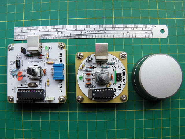
Although you may think a rotary encoder is just a rotary encoder, when selecting one for a specific purpose such as a volume knob, the feel and quality can play a large part in your design decision. You only have to look at the vast part numbers in any given range to appreciate this.
Attiny2313 & Attiny84 V-USB Media Volume Control – [Link]
educ8s.tv uploaded a new video on Raspberry Pi Sense Hat Tutorial:
Dear friends, in this tutorial we are going to take a first look at the impressive Sense Hat add-on board for the Raspberry Pi. It was developed for the Astro Pi mission and 2 of these boards are deployed to the International Space Station. Let’s start!
The Sense HAT is an add-on board for Raspberry Pi, made especially for the Astro Pi mission – it launched to the International Space Station in December 2015. Yes, two Raspberry Pies with 2 Sense Hats were actually sent to the International Space Station and performed experiments with code that was written by students! Amazing stuff!
A first look at Sense Hat add-on board for the Raspberry Pi – [Link]
A how-to on using the BMP180 barometric sensor with the Arduino @ Random Nerd Tutorials:
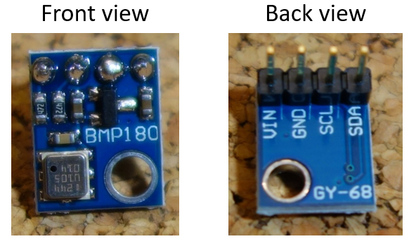
The BMP180 barometric sensor (model GY-68) is the one in the following figure (front and back view). It is a very small module with 1mm x 1.1mm (0.039in x 0.043in).
It measures the absolute pressure of the air around it. It has a measuring range from 300 to 1100hPa with an accuracy down to 0.02 hPa. It can also measure altitude and temperature.
The BMP180 barometric sensor communicates via I2C interface. This means that it communicates with the Arduino using just 2 pins.
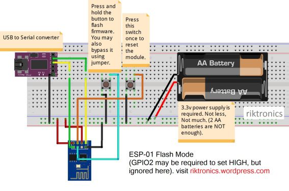
This tutorial is for helping you to flash firmware in your favorite ESP8266 module. First i small introduction to ESP8266:
The ESP8266 is a low-cost Wi-Fi chip with full TCP/IP stack and microcontroller capability produced by Shanghai-based Chinese manufacturer, Espressif. The chip first came to the attention of western makers in August 2014 with the ESP-01 module, made by a third-party manufacturer, AI-Thinker. This small module allows microcontrollers to connect to a Wi-Fi network and make simple TCP/IP connections using AT commands. It also has a decent amount of internal memory (512kb-4mb), so it can also be used as a standalone IoT device with lesser number of GPIO pins.
Flash Firmware To ESP8266 WiFi Module the easy way – [Link]
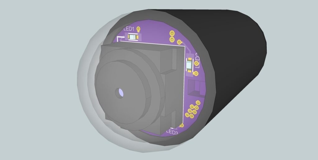
A tiny wireless capsule camera for medical imaging or space-constrained environments. by Ryan Bailey @ hackaday.io:
Tiny, pill-sized cameras are frequently used in the medical field to visualize the gastrointestinal tract, particularly areas not readily accessible by bulkier devices. Increasingly, consideration is given to using these devices in patients who cannot tolerate, or are otherwise unwilling to undergo, a conventional colonoscopy. The possibility of displacing or augmenting these methods with tiny, non-invasive devices is very exciting.
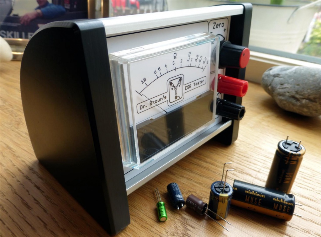
TallMan’s lab @ runawaybrainz.blogspot.com build a nice looking and simple analog ESR capacitor meter based on a EEVBlog forum topic.
I finally got round to making my capacitor ESR tester this week after finding a nice simple 5 transistor version by EEVBlog member Jay_Diddy_B. Unfortunately, for me, the design was only SMD so, I decided to replicate his schematic in Eagle PCB using a through hole component design.
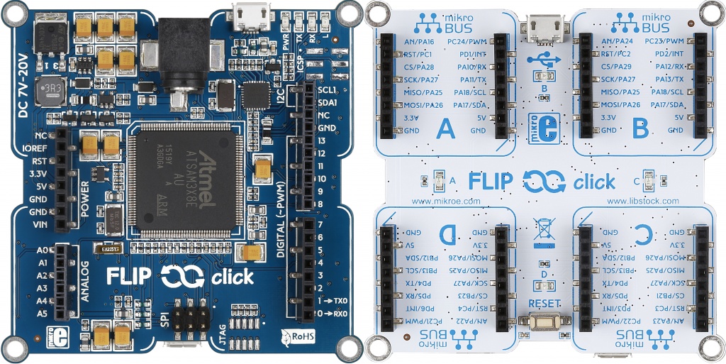
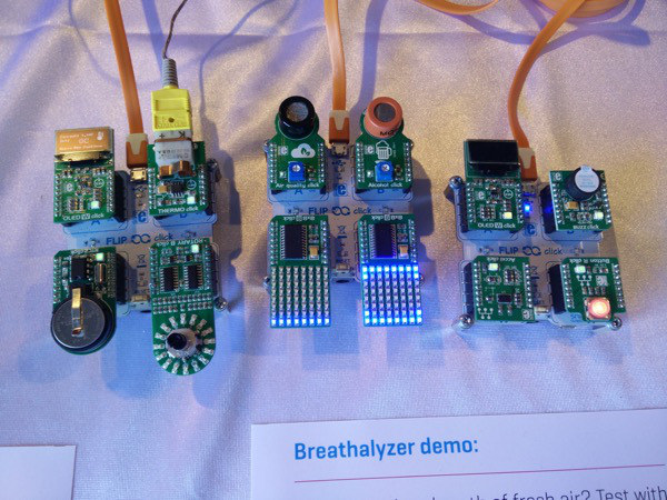
MikroElektronika, the microcontroller development boards and accessory boards manufacturer, introduced a new development board for beginners and non-experts called Flip & Click.
Flip & Click is a rapid prototyping tool that is an Arduino Due on one side, and four mikroBUS™ sockets on the other side.
The Two Sides Of Flip & Click Board
The first side, the blue side, is Arduino Due side, it based on the Atmel ATSAM3x8E ARM® Cortex®-M3 processor which runs at 84 MHz and features 512KB of flash memory and 100KB of SRAM. This side is compatible with Arduino Leonardo shields thanks to its connectors, which makes it easy to expand its functionality and to add more features.
The other side, the white side, is the Click side. It has four mikroBUS sockets marked from A to D and four blue LEDs, also marked from A to D.
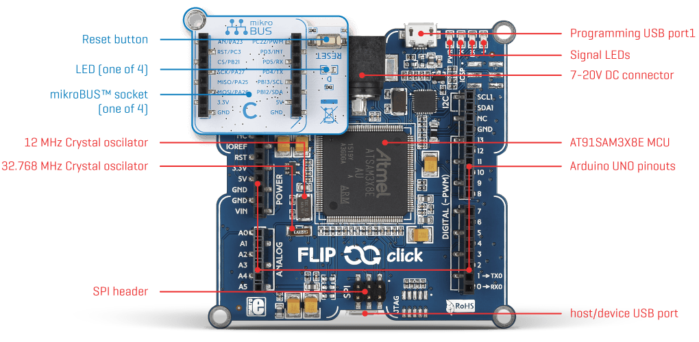
Flip & Click On Board Parts
The mikroBus is a proprietary add-on board interface specification by MikroElektronika (mikroE). It consists of two 8-pin rows that expose I2C, SPI, and serial ports, 5V and 3V3 power supply, an analogue input, a PWM output, and reset & interrupt signals. All these pins, except the power supply ones, can be used as GPIO too. MikroE has developed several hundreds of extension boards for it, many of them have sensors, and there are also GPS, phone and other wireless boards, motor & LED drivers, etc.
Flip & Click board specifications:
MCU – Atmel AT91SAM3X8E Cortex M3 micro-controller @ 84 MHz with 512 KB flash, 100 KB SRAM (64+32+4), also used in Arduino Due.
Expansions Headers
Arduino UNO compatible headers on the top
4x mikroBUS socket on the bottom
USB – micro USB port for programming and power
Misc – Reset button, LEDs
Power Supply – 5V via micro USB port
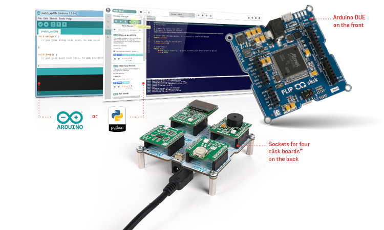
Flip & Click Software & Hardware
Flip & Click can be programed with both Arduino IDE and Python. For Arduino IDE programmers, you need only to plug it in with USB cable, run the IDE and start writing your sketches – it will be recognized as Arduino Due.
For Python lovers, they can use Zerynth Studio and select MikroElektronika Flip & Click from ‘available boards’ after connecting it, then you can start writing your programs.
Flip & Click is available for $39 on its official page where you can also get access to full documentation, resources, and sample projects. Many users have published their reviews about this board and you can find them here and here.
Biosensors for consumer wearable devices is a new trend as it facilitates multiplexed physiological monitoring for quantitative assessment of body functions. Highly functional wearable biosensors that can also provide meaningful diagnostics to guide therapeutics would be extremely valuable to end-user consumers or health-professionals.
Researchers at The University of Texas at Dallas developed a wearable device that is lancet-free, label-free diagnostic sensor which can monitor an individual’s glucose level via perspiration on the skin. They worked with sweat, not any other fluids like urine or tears, since sweat is the most widely evaluated body fluid as it contains a lot of medical information and is relatively easier to stimulate, gather, and analyze. To increase the usability of the sensor, researchers had also tested the combined detection of stress biomarker cortisol in human perspiration using the same sensor platform
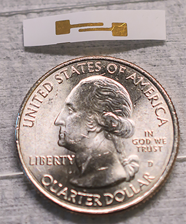
About an Inch Long Small, Flexible, and Rod-Shaped Device
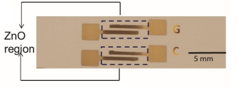
In order to make wearable biosensors as successful consumer products it is important to demonstrate enhanced multiplexed functionality, reliability, and ease-of-use through non-invasive (without skin break) monitoring of body fluids. Thus, researchers designed and fabricated 3-D nanostructured semiconducting ZnO sensing elements to establish optimal electron transfer efficacy between 4 immobilized glucose and cortisol molecules and the electrode surfaces. ZnO has been successfully used as electrode material for enzyme immobilization and glucose detection.
Schematic Of Sensor Setup
“In our sensor mechanism, we use the same chemistry and enzymatic reaction that are incorporated into blood glucose testing strips. But in our design, we had to account for the low volume of ambient sweat that would be present in areas such as under a watch or wrist device, or under a patch that lies next to the skin.” said Prasad, The Cecil H. and Ida Green Professor in Systems Biology Science.
Their design works with volumes of sweat less than a microliter, which is the approximate amount of liquid that would fit in a cube the size of a salt crystal. The system also provides a real-time response in the form of a digital readout.
Glucose monitoring has tremendous importance in the field of diabetes management and this non-invasive detection techniques based on body fluids are pain free, comfortable and offer patient adaptability. However, sweat glucose concentrations have a time lag and concentration range varies with respect to blood glucose concentrations due to the diffusion barriers in human physiology.
The research was supported by the Cecil H. and Ida Green endowed fellowship at UT Dallas.
Switching technology devices and integrated circuits are growing fast providing solutions that obtain power for different kind of circuits and devices, and they are proposed in different variations. A useful little known kind which is suitable for mixed supply systems is called SEPIC,single-ended primary-inductor converter.
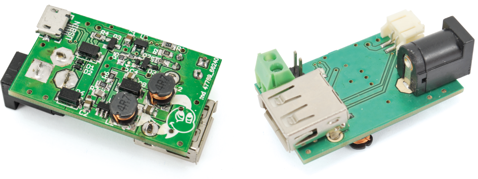
Torpedo is a switched-mode power supply with a SEPIC configuration which is produced by Open Electronics, an open source solutions producer and the brainchild of Futura Group Srl. It supports three different wide-range voltage sources, battery, USB, and external source from 3 to 20 volts with up to 1 A output current and integrated LiPo battery cell charger.
Torpedo Board
Torpedo comes with these features:
Triple power source, that is to say: the USB, the battery and an external one
Wide range of values as for the input voltage: from 3 to 20 volts
Minimum output current of 500mA, with the possibility to reach 1A and more, via an external source
High efficiency, above 70% and possibly above 80-90%
Single-cell LiPo battery charger incorporated
A transition from battery power to another source that is without interruptions
5 V output with high stability, having a low ripple and when varying the load.
Torpedo’s circuit structure can be functionally divided into three different parts; Input Stage, Battery Charger, and SEPIC Converter.
At first, the Input Stage is composed of two diodes and a MOSFET transistor. This set forms a power source selector by allowing the highest voltage power source to pass through Vin pin and prevent it from going to another input having a lower voltage.
Torpedo Circuit Diagram
The Battery Charger is based on the MCP73831-2 integrated circuit, that is envisaged for charging single-cell LiPo batteries having a voltage of 4.2 volts. It comes with a red LED indicating the statues of charging, and a two-resistor bridge giving two different output current, 100mA and 500mA.
The SEPIC Converter in general is a DC/DC converter which control its output to be greater than, less than, or equal to that at its input. In Torpedo circuit, the SEPIC integrated circuit contains 1.2Mhz oscillator with variable duty cycle, a low-RDSON MOSFET, and a feedback circuit. This combination provides constant 5V output voltage from variant input voltage between 2.5V to 20V.
Torpedo is available for $14.5 from Open Electronics store, and its technical details are reachable here.
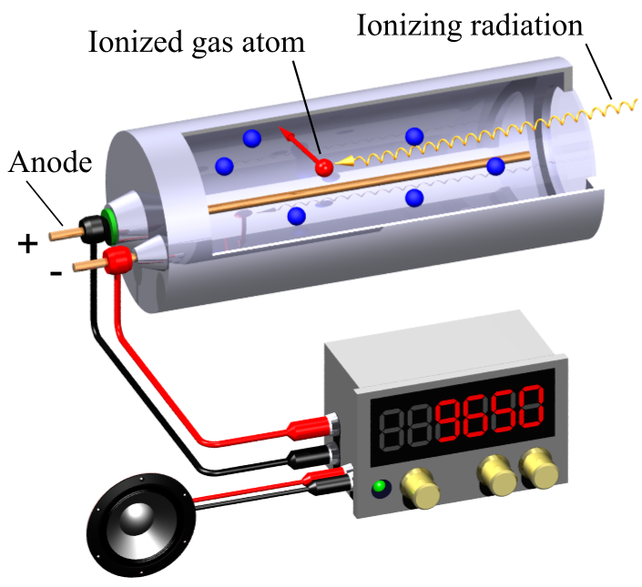
Radioactive particles are found abundantly in nature. Whether they come from space or generated on Earth (radioactive waste, medical X-rays, etc), they are high-energy particles resulting from radioactive decays. The three major types of radioactive particles are named after the first three letters of the Greek alphabet: α (alpha are helium nuclei), β (beta are high-speed electrons), and γ (gamma are high-energy photons). Exposing to any of these radiation for a long time can be dangerous as they can kill DNA and cause cancer. The presence of beta particles and gamma rays in your surrounding can be detected using a Geiger-Muller (GM) tube in conjunction with some basic electronics.
The GM tube is essentially a tube filled with an inert gas (at low pressure) and two electrodes at its opposite ends. A high voltage (~400-700V) is applied between the two electrodes but no current flows between them under normal condition. When radioactive particles passes through the tube, some of the gas molecules get ionized, which results in a short intense pulse of current between the electrodes.
Geiger-Muller tube operation (Source: Wikipedia)
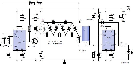
The following circuit (originally published on Elektor July 2006 magazine) illustrates how a GM tube can be used with some basic electronics to make a radiation detector, often known as Geiger counter. The circuit uses two 555 timer ICs. The first 555 timer is setup as an astable multivibrator and drives a step up (6V-to-250V) transformer through a transistor to generate 250V alternating voltage. The high voltage output from the transformer is further amplified using a voltage multiplier circuit made of diodes and capacitors to derive a ~700V source required for the GM tube. When a radiation is detected, the current flow through the tube triggers the second 555 timer circuit, which is configured to produce a tick sound on a speaker when triggered. The output from the second 555 timer can be further fed to a counter circuit for counting the detected pulses.
Geiger counter using 555 timer ICs
More recently, tanner_tech published an Instructable on building a similar Geiger counter using a single 555 timer and a piezo buzzer. His GM tube operates at a much lower voltage (~400V).


![Geiger counter made by [tanner_tech]](https://www.electronics-lab.com/wp-content/uploads/2016/10/5552.jpg)