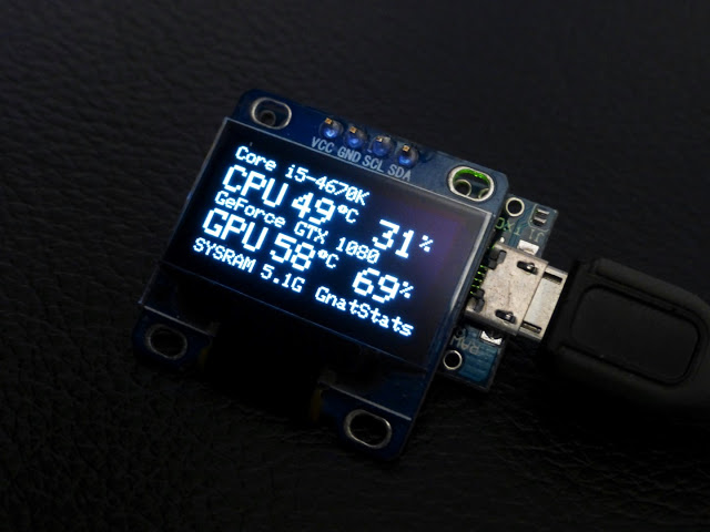
Rupert Hirst build a tiny OLED PC performance monitor based on Psyrax’s serial monitor. The display monitors CPU and GPU temperature and activity etc. He writes:
After a recent purchase of a Nvidia GTX1080 graphics card, 4k monitor plus Doom(2016), I thought it would be great to see some external telemetry… from my exorbitant purchase.
Then, I Stumbled upon on Psyrax’s “Serialmonitor” GitHub repository! Armed with an Arduino ProMicro plus a 128×64 pixel OLED display, I compiled the source code. After compiling Psyrax’s windows application in Visual Studio, I got to work.
dannyelectronics.wordpress.com discuss about how to build a mcu based LED vu meter and provides sample code.
From time to time, I see people trying to build an audio VU meter. In the analog era, that’s typically done with a voltage divider + a series of comparators; or using chips like LM3914/3915.
Those chips are harder and harder to find, or you may need more resolution, or a different output profile. What to do?
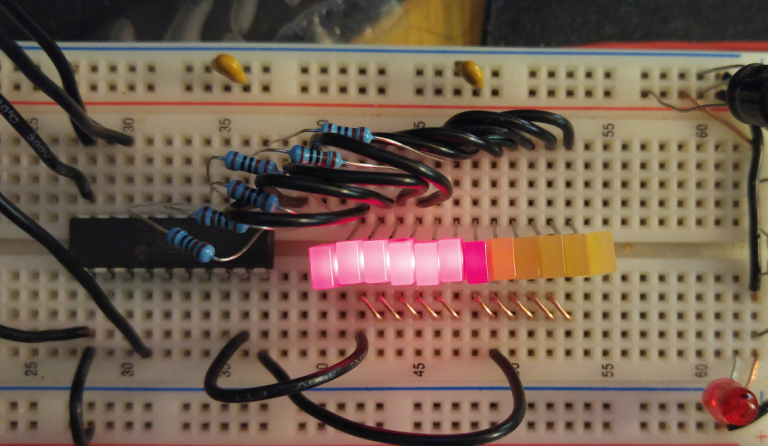
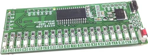
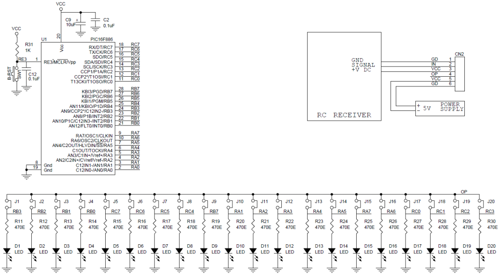
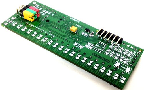
The versatile Bar-Graph SMD components based R/C monitor & R/C switch is a great tool for R/C hobbyist R/C modeller and DIY robotics. Tiny Bar-Graph displays provide a Red color bright, easy to read display of Radio Control (R/C) signal from 1mS to 2mS. The Barograph RC Signal reader is based on PIC16F886 microcontroller. This high performance measurement device, provides unique capabilities and can be used in various applications like Radio Signal Monitor, Robotics, Machine Control, RC Remote Tester, RC Signal ON/OFF switch by connecting Relay board or Solid state relay at output of any suitable LED. Solder Jumpers provided on bottom side of PCB to select particular output to interface with Relay or Solid state Relay.
RC Signal Monitor Using Bargraph & RC Switch using Relay – [Link]
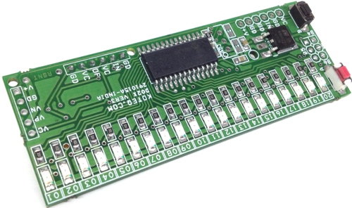
The versatile Bar-Graph SMD components based R/C monitor & R/C switch is a great tool for R/C hobbyist R/C modeller and DIY robotics. Tiny Bar-Graph displays provide a Red color bright, easy to read display of Radio Control (R/C) signal from 1mS to 2mS. The Barograph RC Signal reader is based on PIC16F886 microcontroller. This high performance measurement device, provides unique capabilities and can be used in various applications like Radio Signal Monitor, Robotics, Machine Control, RC Remote Tester, RC Signal ON/OFF switch by connecting Relay board or Solid state relay at output of any suitable LED. Solder Jumpers provided on bottom side of PCB to select particular output to interface with Relay or Solid state Relay.
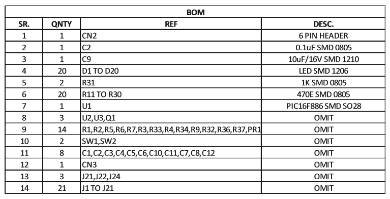
Note: This board has been designed for multiple options and has few extra components. Check BOM carefully before soldering the components. Solder the parts as described in parts list.
Features
Supply 5V DC
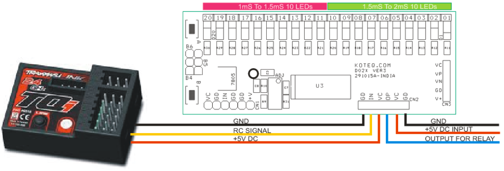
Input 1mS to 2 ms
Display Range 1.5mS to 2mS Center to Left 10 LEDs & 1.5mS to 1mS Center to Right 10Leds
Output Display 20 Color RED SMD LEDs
Compact Board with SMD Components
Supply input Header Connecter
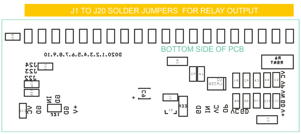
Solder Jumper on each LED for Output Control, Alarm, and Relay
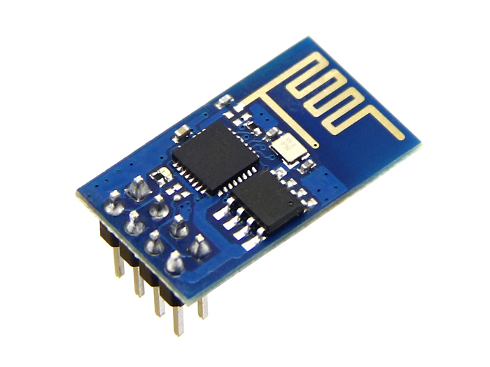
Piers Finlayson shares his adventures in programming the ESP8266 to access 16MB flash:
To put this in context, the original ESP8266 modules (such as the ESP-01) offered 512KB of flash, with the more recent ones (ESP-07) 1MB and then 4MB. The maximum addressable flash memory of the ESP8266 is 16MB according to the datasheet. (The ESP32 offers up to 4 x 16MB of flash.)
I don’t have a particular need for > 4MB flash (otb-iot currently only requires and supports 4MB) but my interest was tweaked in the larger flash chips, so I thought I’d give it a go. I’ve experience of replacing flash chips from older modules to upgrade them from 1MB to 4MB, so figured 16MB would be the same.
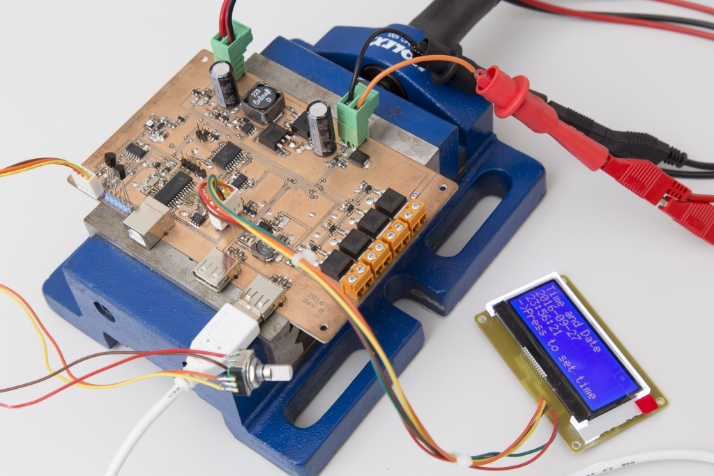
Lukas Fässler show us his progress on the MPPT solar charger:
One of my main goals with this design is to achieve very low standby current, somewhere in the tens of microamps. The basis for this is a low-power buck on the basis of a Texas TPS62120 where the microcontroller can switch the output voltage between 2.2 and 3.3 volts nominally. This works as intended. With no load and the output voltage low, the supply consumes 12.9 microamps at 12V input voltage. With the high output voltage the idle current goes up to 14.3uA. Quite a bit of that current is due to the voltage divider that sets the output voltage. The regulator itself consumes about 9uA in both cases.
educ8s.tv uploaded a new video on a RFID Arduino Tutorial:
Today we are going to build a very interesting project. For the first time we are going to use RFID tags with Arduino. I have built a simple project which reads the Unique ID (UID) of each RFID tag we place close to the reader and displays it on this OLED display. If the UID of the tag is equal to a predefined value that is stored in Arduino’s memory, then in the display we are going to see the “Unlocked” message. If the Unique ID of the card is not equal to the predefined value, the Unlock message won’t appear. Cool isn’t it?
RFID Tutorial with an Arduino Uno and an OLED display – [Link]
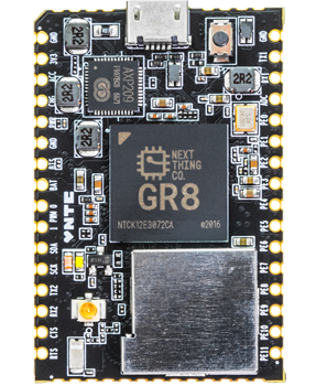
NextThing Co., is a hardware company that has the goal to create things that would inspire creativity, and help people chase their own ideas of what needed to exist. After producing their world’s first $9 computer C.H.I.P, they are ready now to launch a new product!
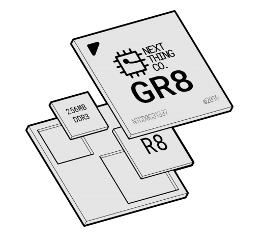
C.H.I.P Pro, the newest addition to the Next Thing Co. family, is powered by GR8, a system-in-package (SiP) that was designed by Next Thing Co. GR8 features a 1GHz Allwinner R8 ARM Cortex-A8 processor, Mali400 GPU, and 256MB of Nanya DDR3 DRAM. in a 14mm x 14mm FBGA package. C.H.I.P. Pro is a system-on-module (SoM) that has 512MB of high-speed NAND storage flashed with NextThing Co.’s GadgetOS. Gadget is an Open Source Linux-based OS, software toolchain, and cloud infrastructure which is designed to bring the speed, openness, and productivity of modern software development to the world of embedded hardware. C.H.I.P Pro can be powered by USB or battery, intelligently managed by the AXP209 power management unit.
The Pro also features 802.11 b/g/n WiFi, Bluetooth 4.2, and is fully certified by the FCC. This board will be available in December at supposedly any quantity for $16.
C.H.I.P Pro block diagram
C.H.I.P Pro design defines two possibilities of installations; either in a product or in a single board computer designed for a breadboard. Its SMT-ready castellated edges and elements on both sides will make reflow soldering not so preferable. Instead, header pins, a ‘debug board’, and two C.H.I.P Pro units are introduced in one package for only 49$ to make soldering easier and to start installing the unit in applications. Due to its size and efficiency, it could be a good competitor for Raspberry Pi Zero.
C.H.I.P. was designed to be used in computer powered products, but it was recognized later that it wasn’t always the best fit. Many of the design choices of C.H.I.P make it hard to build into products. C.H.I.P. Pro addresses this issue, implements feature requests from the community, and is engineered to embed in products. C.H.I.P. and C.H.I.P. Pro are similar in many important ways, but they differ in some features. Here are C.H.I.P Pro advantages:
USB Breakout for PCB Designs incorporating USB based peripherals
Breadboard and SMT Placeable
A complete suite of certifications: WiFi Alliance, Bluetooth Consortium, FCC, CE, ROHS
Based on GR8 making it 76% smaller than C.H.I.P.
Better power consumption with ~3mA suspend to RAM
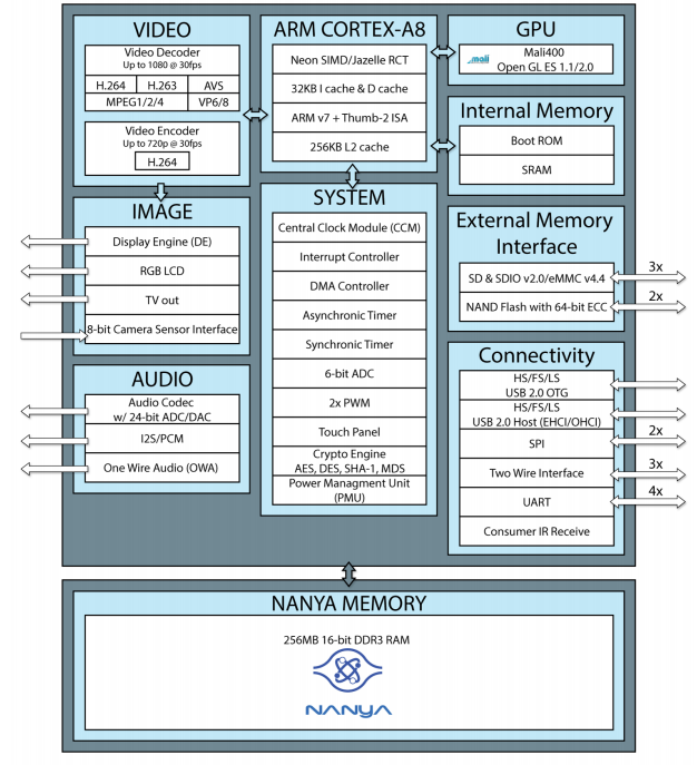
C.H.I.P. Pro is powered by GR8, a system-in-package provides a powerful application processor and DDR3 SRAM which eliminates the need for high-speed routing and reduces manufacturing complexity. GR8 is $6 in any quantity and includes the Allwinner AXP209 power management unit.
GR8 also features many popular peripheral interfaces: Two-Wire Interface, two UARTs (one 2-wire and one 4-wire), SD Card-ready SPI, two PWM outputs, a 6-bit ADC, I2S digital audio, S/PDIF IEC-60958 digital audio output, two HS/FS/LS USB PHYs (one USB 2.0 Host and one USB 2.0 OTG), a CMOS Sensor Interface.
GR8 Block Diagram
Although it is doubtless that C.H.I.P. Pro will be installed and used in various projects, making GR8 module available for customers is something huge. Providing a jellybean part that contains an entire Linux system makes it possible to add the power of open software into any project and it opens the door for more applications to come.
Further details can be reached at C.H.I.P Pro and GR8 datasheets and at NextThing Co. forums.
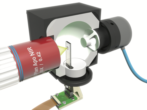
Researchers from the AMOLF institute and Eindhoven University of Technology have developed a theory and an experimental method that for the first time provide a detailed description of how a nanoscale solar cell works. Previously this was difficult due to the extremely small dimensions of these solar cells. This new method brings the practical use of nanotechnology for sustainable energy supply a step closer.
Silicon Labs, an energy-friendly solution provider, produced a new family of Wireless Gecko modules for mesh networking applications and supporting ZigBee and Thread software.
Mesh network is a network topology which each node relays data for the network. All mesh nodes cooperate in the distribution of data in the network. It is used by wide range of applications such as home automation, smart metering, connected lighting, security systems, and IoT applications.
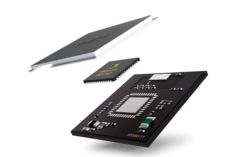
Silicon Labs MGM111 Module
Based on the Silicon Labs EFR32™ Mighty Gecko SoC, MGM111 module is a fully-integrated, pre-certified module, accelerates time-to-market and saves months of engineering effort and development costs. It combines an energy-efficient, multi-protocol wireless SoC with a proven RF/antenna design and industry leading wireless software stacks.
The module consists of ARM Cortex®-M4 controller with up to 40 MHz clock speed, 2.4 GHz transceiver, 256 kB of programmable flash, and 32 kB RAM SRAM. It consumes only 9.8mA while in receive mode and 8.2mA at 0dBm when in transmit mode, with a transmit power of up to 10dBm.
“Our customers rely on our deep understanding of mesh technology and RF certification. They also appreciate that we offer the tools and stacks they need to simplify the development process, as well as an upgrade path that safeguards their IoT products from being stranded on older technologies and standards.” -Skip Ashton, VP of IoT software at Silicon Labs.
Thread is an IPv6-based mesh networking protocol designed as a reliable, low-power, secure, and scalable networking solution for connecting Things to the IoT. As a founding board member of the Thread Group, Silicon Labs helps accelerate time to market with proven mesh networking hardware and software solutions.
ZigBee is an IEEE 802.15.4-based specification for a suite of high-level communication protocols used to create personal area networks with small, low-power digital radios.
The MGM111 module datasheet with its full specifications list are reachable here.


 C.H.I.P Pro
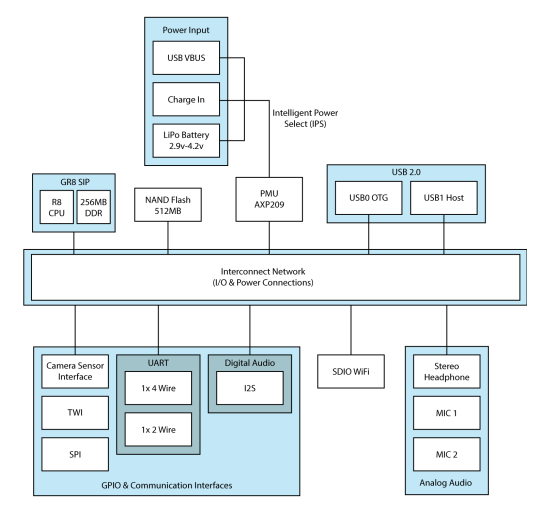
 C.H.I.P. Pro is powered by GR8, a system-in-package provides a powerful application processor and DDR3 SRAM which eliminates the need for high-speed routing and reduces manufacturing complexity. GR8 is $6 in any quantity and includes the Allwinner AXP209 power management unit.