Spectral signature is a characteristic property of a material that represent how the matter interacts with an electromagnetic radiation at different wavelengths. By looking at the reflectance spectra of a material, scientists can not only retrieve vital information like the chemical composition and crystal structure of the material, but also the presence of any impurities or third element within it. The instrument used to derive such spectra is called Spectrometer. While a commercial spectrometer could cost a huge amount of money, Akshat Wahi‘s work is intended to make an open-source tool called WiSci to allow spectroscopy accessible to everyone.
DIY spectrometer
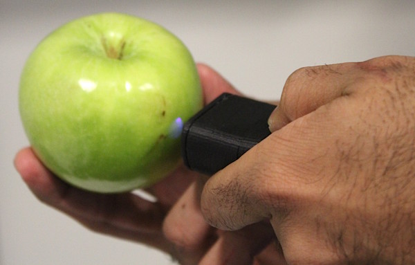
WiSc is a portable spectrometer that communicates to an Android device over Bluetooth to store and visualize the spectral data. It uses Hamamatsu’s C12666MA mini-spectrometer at the front end to collect spectral signature from a target in wavelengths ranging from 340 to 780 nm. The hardware setup includes an Arduino board to read measurements from C12666MA and a HC-05 Bluetooth module for sending the data to the Android device. The android application was developed using Android Studio IDE and is compatible with Android 2.3.3 or higher.
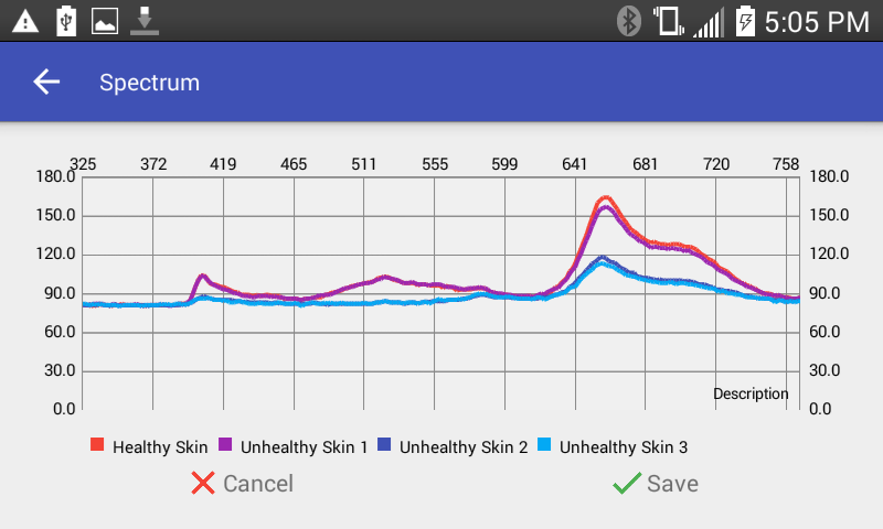
Chlorophyll fluorescence from apples
Akshat’s team tested WiSc for non-destructive testing of fruit ripeness. They collected Ultra-Violet (UV) fluorescence from Chlorophyll present in the skin of Red Delicious, McIntosh and Empire apples. Their observations were found consistent with what is measured by a penetrometer.
Linaro, a collaborative engineering organization consolidating and optimizing open source software and tools for the ARM architecture, is bringing together industry and the open source community to work on key projects, reduce industry wide fragmentation, and provide common software foundations for all. During the last Linaro Connect event at Las Vegas, a new BLE (Bluetooth Low Energy) product had been debuted!
The BLE Carbon is joint efforts by Linaro, 96Boards, and Seeedstudio, aims to provide economic and compact BLE solutions for IoT projects.Carbon is the first board to be certified 96Boards IoT Edition compatible that targets the Internet of Things (IoT) and Embedded segments.
While 96Boards, the open hardware standardization group, has an IoT Edition (IE) specification for low-cost ARM Cortex-A and Cortex-M development boards, it also has another two: the Consumer Edition (CE), the Enterprise Edition (EE).
Although Linaro and 96Boards named this board “Carbon”, Seeedstudio choose “BLE Carbon” which may reveal some future plans to produce other editions with the same technology.
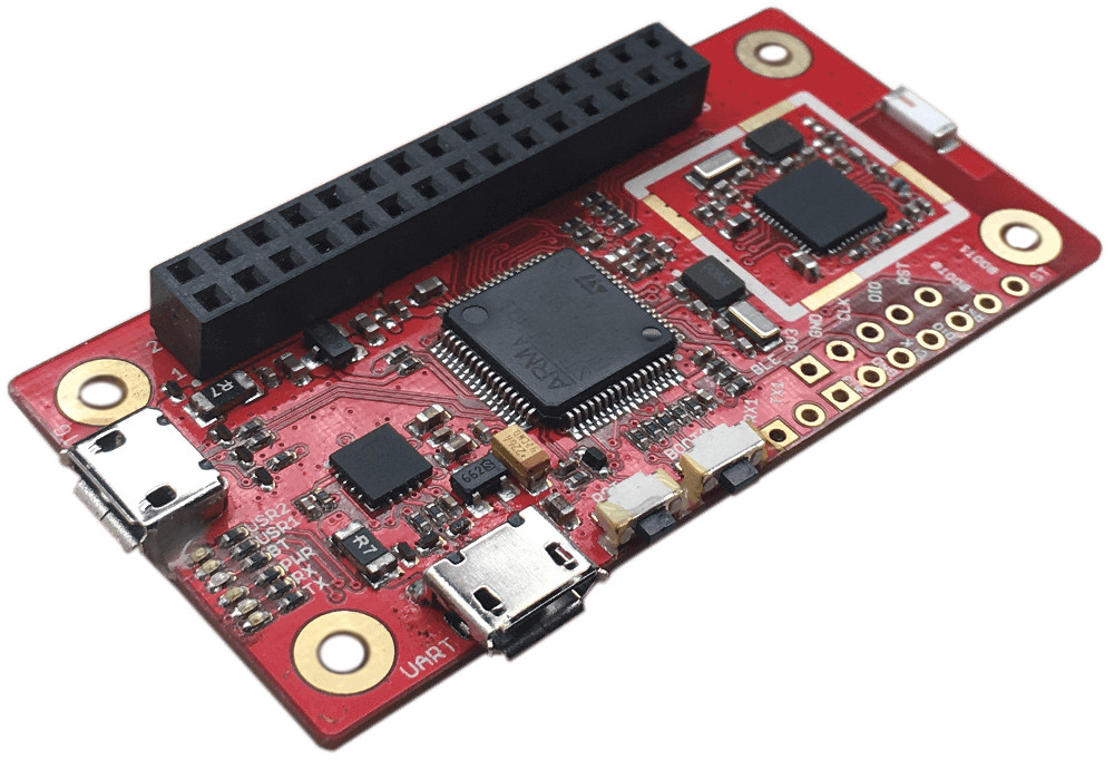
BLE Carbon
Carbon has a Cortex-M4 chip, 512KB onboard flash, built in Bluetooth, and a 30-pin low speed expansion header capable of up to 3.3V digital and analog GPIO. Moreover, Carbon is the first SBC (Single Board Computer) to run the Linux Foundation’s Intel-backed Zephyr OS which is an open source, small, scalable, real-time OS for use on resource-constrained systems and IoT devices. A technical overview of Zephyr is available in this video.
The 60 x 30mm SBC preloaded with Zephyr RTOS runs on ST’s STM32F401 microcontroller. It also features two micro-USB ports, one of which is used for power, and has the required 30-pin low-speed connector. Analog pins and debug connectors are also onboard. In addition to 6x LEDs, reset, and boot buttons.
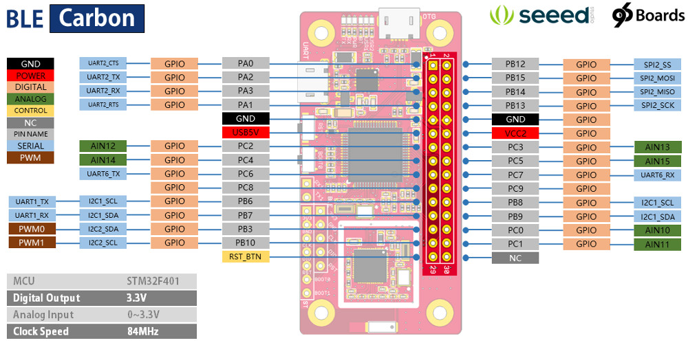
BLE Carbon Pin Assignments
Here are BLE Carbon full specifications:
Processor — ST STM32F401 (1x Cortex-M4 @ up to 84MHz)
Memory (via STM32F401) — 96KB RAM; 512KB flash
Wireless — Bluetooth LE (2.4GHz nRF51822); chip antenna
Other features — 6x LEDs (UART Tx and Rx, power, BT, 2x user); reset and boot buttons
Power — Micro-USB based with fuse protect; 3.3V digital out; 0-3.3V analog in
Dimensions — 60 x 30mm
Operating system — Zephyr
How to use BLE Carbon
Here are what you need to start setting up the board:
USB to MicroUSB cable (x2)
This is needed for serial console interface and USB-OTG (including DFU support)
Switches
Two switches are provided: RST to reset the STM32F401 chip, BOOT0 to enter the STM32F4 bootloader
Pin headers (unpopulated)
Tx/Rx UART for STM32F4 chip
5-pin SWD interface to STM32F4 chip
BOOT0 and BOOT1 lines exposed
5-pin SWD interface to nRF51 chip
To start the board for the first time just connect the micro-USB cable to supply power to the Carbon. The board will begin to boot Zephyr immediately. You can use either of the micro-USB ports to power the Carbon. Currently, Linux is the only supporting host system for Carbon while Windows and Mac OS support is coming soon. Some Linux host applications are available here.
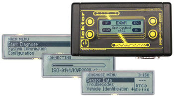
Thomas Beck started a new project to develop a Raspberry Pi based OBD2, On-Board Diagnostic tester, to read vehicle data, trouble codes, and read monitor data. He had developed earlier a firmware for the elektor OBD Analyser NG, a handheld analyser with graphical display, ARM Cortex M3 controller and open source user interface. Since this device is not available anymore, he is working on a new one.
The On-Board Diagnostics is a system that makes status of all vehicle subsystems reachable by the vehicle owner or the repair technician, the data are requested from the vehicle through a list of predefined codes, then the OBD device will process and display them.
The Old Elektor OBD Analyser NG
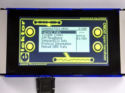
The Raspberry Pi must have similar interfaces to the OBD Analyser NG. On the user side there is a serial interface which is available at the Raspberry Pi GPIOs, but on the vehicle side a DIAMEX DXM OBD2 module is used. Thus, Thomas decided to develop a simple add-on board to make the module compatible for using with Pi.
Thomas used the DXM on his own OBD2-Analyser NG for prototyping the idea, and share his successful results with DIAMEX, the manufacturer of the DXM module, which accepted the idea and developed a Pi-OBD add-on board based on their modern AGV OBD2 module.
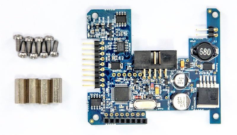
The Pi-OBD add-on board consists of an DIAMEX AGV OBD2 interface with an automotive-proven power supply/voltage regulator for the AGV, the Pi and a display. It has a PCB that suitable with the Raspberry Pi B+, 2 and 3. The complete system is powered via the OBD2 cable. The Pi-OBD uses a few GPIOs and covers some more. So, using a display connected via an HDMI ribbon cable is recommended.
DIAMEX Pi-OBD Add-On Board
As a result, there are two options to add OBD2 to Raspberry Pi:
OBD2 for Raspberry Pi using the DIAMEX Pi-OBD add-on board, it needs:
Pi-OBD add-on board
OBD2 cable
7″ touchscreen
Raspberry Pi/Raspbian with free serial device, e.g. /dev/ttyAMA0 or /dev/ttyS0
HHGui OBD2 software for the Pi
OBD2 for Raspberry Pi using the DIAMEX DXM OBD2 module, it needs:
XM OBD2 module
A few additional parts like PCB (a breadboard will do), wires, connector for GPIOs, connector for OBD2 cable, optional but recommended: 2 resistors, 1 capacitor, 1 diode
OBD2 cable
Vehicle 12V socket to USB adapter + USB cable to power the Pi and the display
Raspberry Pi/Raspbian with free serial device, e.g. /dev/ttyAMA0 or /dev/ttyS0
Display for the Pi (minimum display size 320 x 165 pixels)
HHEmu OBD2 software for the Pi
This project is still in the development phase and it is open source. All technical details are available at its official page.
Use of traffic navigation apps to minimize the wait time on road is very common for drivers these days. Google navigation gathers data from the drivers who are navigating via Google Maps and shows the traffic flow on smartphones in real time. While this is a great feature to have in smartphone, it would be nice to have access to the same information in a much simpler way without the need to open the app. That’s exactly what this traffic status display wall clock does.
Traffic status indicator clock
A regular IKEA wall clock is modified to have 12 RGB LEDs placed around it. The LEDs glow with different colors to indicate different traffic status. The LEDs are controlled by an Arduino board and 1sheeld. If you are not familiar with 1sheeld, it is an Arduino shield that allows the smartphone to be used as 40 different kinds of shields. Smartphones are equipped with many built-in sensors and a very high quality display. 1sheeld acts as a bridge between the smartphone and the Arduino board in providing access to all those features of smartphone. The link between the smartphone and 1sheeld is through Bluetooth. For this project, the 1sheeld retrieves the traffic information from the smartphone using Google Distance Matrix API and make it available to Arduino board, which in turn decides what color is to display using the RGB LEDs.
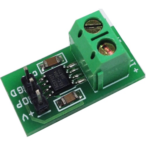
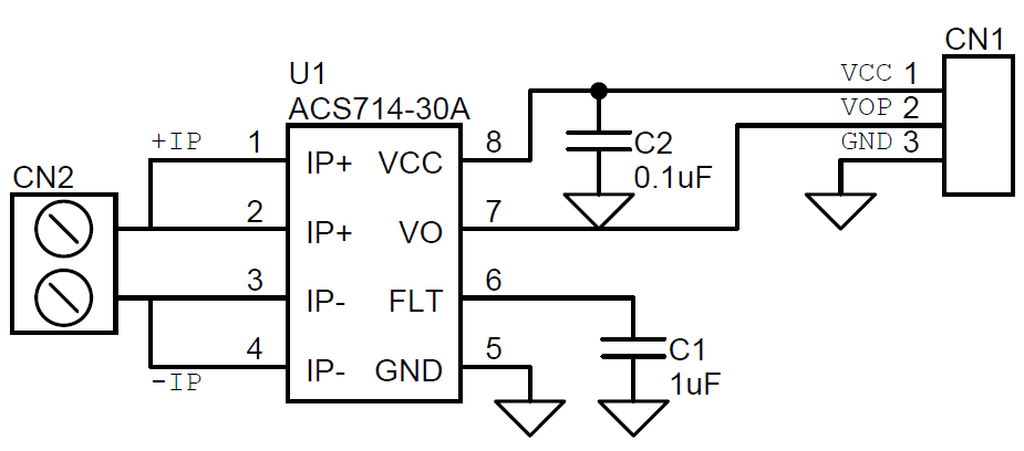
The Allegro ACS714-30A provides economical and precise solution for AC or DC current sensing in automotive systems. The device package allows for easy implementation by the customer. Typical applications include motor control, load detection and management, switched-mode power supplies, and overcurrent protection.
The Allegro ACS714-30A provides economical and precise solution for AC or DC current sensing in automotive systems. The device package allows for easy implementation by the customer. Typical applications include motor control, load detection and management, switched-mode power supplies, and overcurrent protection.
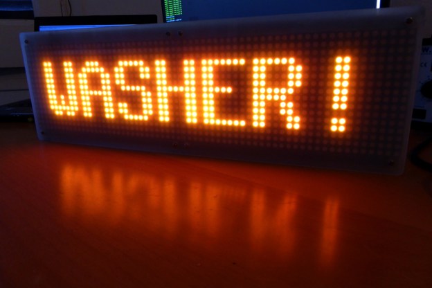
Xose Pérez @ tinkerman.cat build a MQTT LED matrix display to get notification messages.
My MQTT network at home moves up and down a lot of messages: sensor values, triggers, notifications, device statuses,… I use Node-RED to forward the important ones to PushOver and some others to a Blynk application. But I also happen to have an LED display at home and that means FUN.
Coping with rapid technological advances and finding efficient energy solutions are the keys for development of power electronics of the future. A new research had been done in North Carolina State University about increasing the efficiency of high-power switches.
Silicon Carbide is a compound of silicon and carbon with chemical formula SiC. It is a wide bandgap (WBG) semiconductor, that allows devices to operate at much higher voltages, frequencies and temperatures than conventional semiconductor materials.
Researchers came up with a high voltage and high frequency silicon carbide (SiC) power switch that could cost much less than similarly rated SiC power switches. This research may guide to new applications in power converters like medium voltage drives, solid state transformers and high voltage transmissions and circuit breakers.
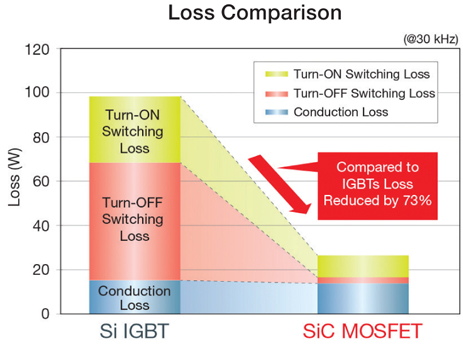
Semiconductor devices like the 15kV SiC MOSFET can lead to great potential applications in high voltage and high frequency power converters. However, these devices are not commercially available and their high cost displaces them from industry competition with other alternatives like the standard IGBT (Insulated-gate Bipolar Transistors) that are widely used, but in the same time they dissipate a lot of energy while switching on and off.
Loss Comparison between Silicon IGBT and SiC MOSFETs
The new SiC power switch, called FREEDM Super-Cascode Switch, contains a series of 1.2kV SiC power devices to produce a 15 kV and 40 mA output that can transcend the 15 kV SiC MOSFET in ease of adoption and cost – since it costs only one third of the estimated high voltage SiC MOSFETs. In addition, this new switch is capable of operating in a wide range of temperatures and frequencies due to its proficiency in heat dissipation, which is considered an advantage in power devices.
FREEDM Super-Cascode SiC Switch
Since there is no high voltage SiC device commercially available at voltage higher than 1.7 kV, as Alex Huang said – Progress Energy Distinguished Professor, he assures that this solution paves the way for power switches to be developed in large quantities with breakdown voltages from 2.4 kV to 15 kV.
The research took place in North Carolina State’s FREEDM Systems Center which is funded by National Science Foundation. This center’s mission is to modernize the electric grid and mold the generation of leaders by providing all the needed software and hardware tools, funds, and partnerships with Industries. This project had also participated in IEEE Energy Conversion Conference & Expo on September 2016 and it was presented by Xiaoqing Song, a Ph.D. candidate at the FREEDM Systems Center under Huang’s supervision.
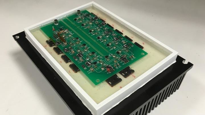
Time and date information may be essential requirements for developing a hardware project, such as registration systems, alarms, and smart pills box. These information can be obtained locally by RTC (Real Time Clock) and RTCC (Real Time Clock Calendar) circuits like DS1307 from Maxim Integrated.
Microchip, an embedded control solutions company, produced MCP7941X three-member family of low power RTCCs with EEPROM and SRAM. Each of MCP79411 and MCP79412 has a unique MAC address that can be programmed by the end user for the networking applications. MCP79411 uses 48-bit MAC address and MCP79412 uses 64-bit one. MCP79410 is suitable for non-network applications as it has the same features except the unique ID.
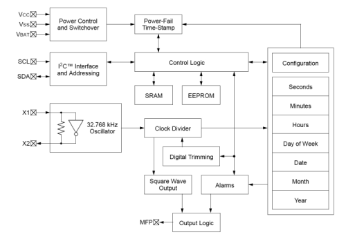
These integrated circuits are compatible with I2C™, include a battery switchover circuit for backup power, and use a low-cost 32.768 kHz crystal, providing time tracking in 12 or 24 hour format and two settable alarms to the second, minute, hour, day of the week, date or month. They also have programmable output pin which can be set as an alarm out or a selected frequency clock out.
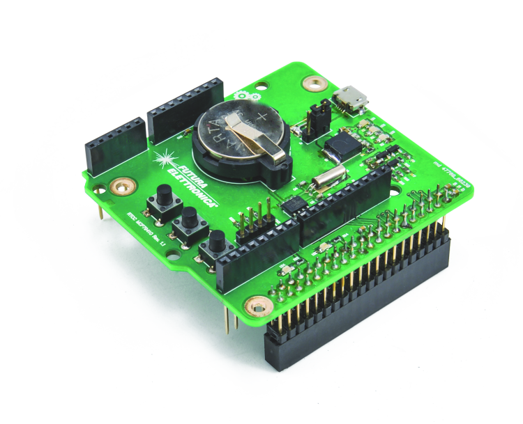
The shield PCB contains the MCP79410 chip, SMD components, CR2032 battery holder, male and female stripps, and three buttons. The three buttons are connected with the Arduino and Raspberry Pi and they are used for the configuration process.
The RTC Shield
There is also a library which allows you to use and program the shield easily. It contains three files, two of them are the functions and theirs declarations, and the third is a text file contains the keywords of public functions and theirs usage.
The shield is available for $18.5 (16.50€). You can order it from open-electronics store and have access to the libraries and example sketches.
Full documentation of the shield with its schematics and diagrams is available here.
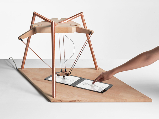
Robots intelligence is going beyond borders and it may outsmart humans in some common games. Right now, these robots have their own personalities and if you are not skilled enough, they might get upset with you!
The interactive Delta three-arm robot, Deltu, is able to interact with humans. This Interactive design consists of 3 arms, an Arduino mind, a ‘personality’, and two iPads that run Unity3d applications. A HTTP request is send to the computer by the human’s application and then a Python server sends strings and commands to Arduino for controlling the robot.
Deltu uses three different applications using symmetry as an interpretation, a mirror and a reflection of our own image. The first game “Together” is a drawing game where Deltu imitates and interprets what we draw. The second one is a battle between the machine and the human. And the final third one is a memory game where the human must learn from the robot. These games were designed to emphasize the special relationship with robots and its evolution.
Deltu uses two iPads to play mimicking games with a human opponent. This sounds amazing – until you know that Deltu is very demanding. Once the opponent makes a mistake, it may stop and take selfies or browse apps. The robot creates patterns by pressing particular tiles on an iPad. If the movements are not mimed precisely, it will shake its adjoined arms in a side-to-side motion that appears to simulate frustration. Then, the robot exits the game and opens the camera app instead.It snaps a few photos of itself and uploads these to Instagram. It even takes a few moments to browse the Explore section and follow a new account, and looks through SoundCloud.
To understand how the robot would work, check it in action
According to the creators, the project explores the relationship between humans and artificial intelligence, as the role of these systems in society has not yet been defined.
This relationship is not only making our performance better, also it may become a source of learning. Currently, this project only supports iOS and works on iPads.
Deltu Interactive designer, Alexia Léchot, had also created other interactive games during her graduate study in ECAL – University of Art and Design in Lausanne, Switzerland.