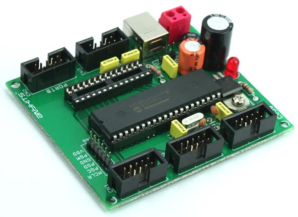
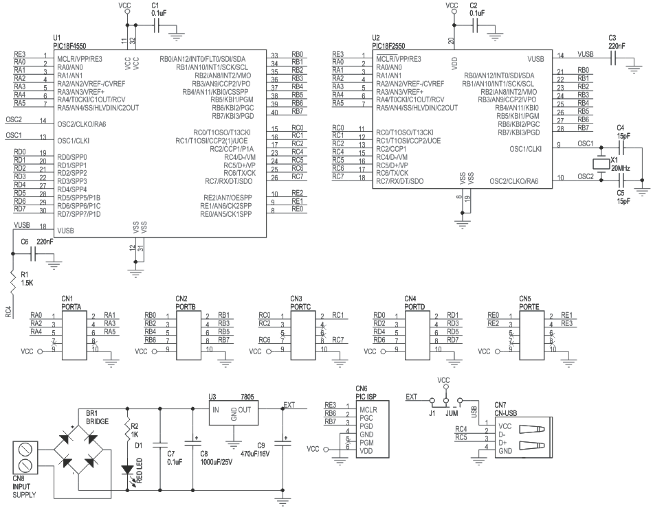
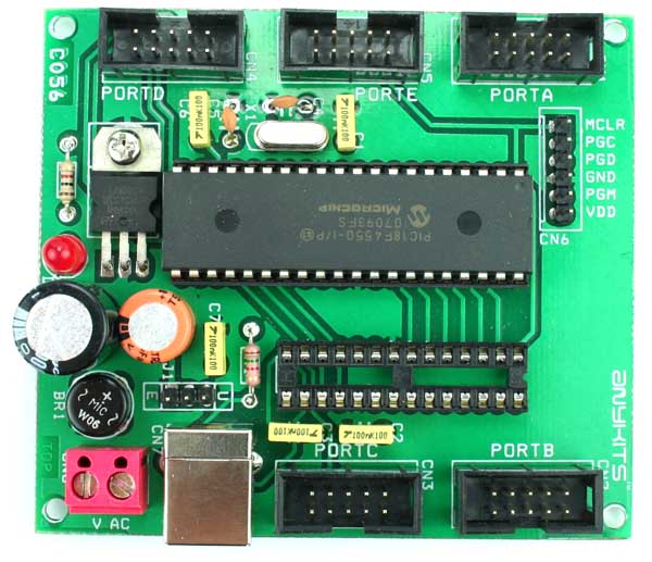
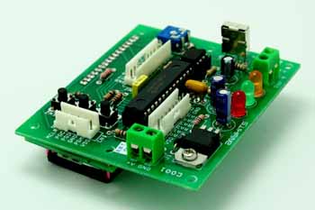
PIC18F USB Development Board will help you with your prototyping requirement with any 28/40-pin Microchip microcontroller supporting USB interface . The board has been tested using PIC18F4550 40 Pin & PIC18F2550 28 Pin Microcontrollers.
Features
All ports terminating in separate Box Header with 5 VDC source option
ICSP connector for programming for the PIC’s with ICD support
Bridge in the input provides any polarity DC supply connection to the board
20 MHz crystal source
Onboard +5V Voltage regulator
Four mounting holes of 3.2 mm each
PCB dimensions 77 mm x 87 mm
40 PIN & 28 PIN PIC18F USB Development Board – [Link]
PIC18F USB Development Board will help you with your prototyping requirement with any 28/40-pin Microchip microcontroller supporting USB interface . The board has been tested using PIC18F4550 40 Pin & PIC18F2550 28 Pin Microcontroller.
Features
All ports terminating in separate Box Header with 5 VDC source option
ICSP connector for programming for the PIC’s with ICD support
Bridge in the input provides any polarity DC supply connection to the board
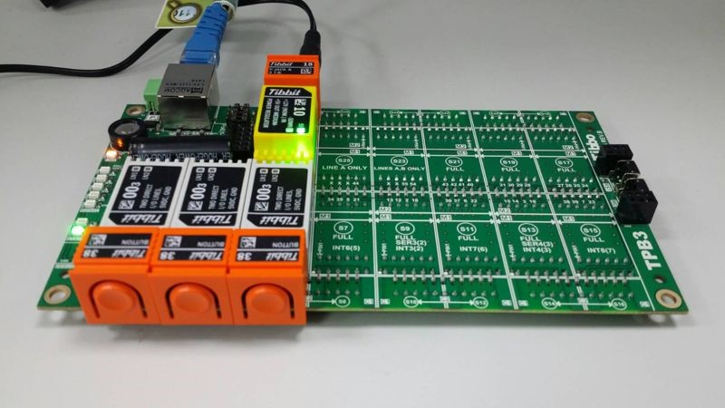
Tibbo created two small programs that illustrate how easy it is to write MQTT-enabled apps in Tibbo BASIC or Tibbo C.
To illustrate the use of the MQTT library, we have created two simple Tibbo BASIC applications called “mqtt_publisher” and “mqtt_subscriber”.
In our MQTT demo, the publisher device is monitoring three buttons (Tibbits #38). This is done through the keypad (kp.) object.
The three buttons on the publisher device correspond to the red, yellow, and green LEDs (Tibbits #39) on the subscriber device.
As buttons are pushed and released, the publisher device calls mqtt_publish() with topics “LED/Red”, “LED/Green”, and “LED/Red”. Each topic’s data is either 0 for “button released” or 1 for “button pressed”. The related code is in the on_kp() event handler.
The subscriber device subscribes to all three topics with a single call to mqtt_sub() and the line “LED/#”. This is done once, inside callback_mqtt_connect_ok().
With every notification message received from the server, the subscriber device gets callback_mqtt_notif() invoked. The LEDs are turned on and off inside this functions’s body. Continue reading “Tibbo – MQTT Library Demo”
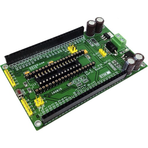
The dsPIC Development board has been designed mainly for Motor dsPIC30F4011 Digital Signal Controller in the 40-pin motor control socket and dsPIC30F4012 28 Pin digital signal controller, the board can also be used with other dsPIC ICs. Board provided with 3.3V and 5V regulator, crystal oscillators and a programming connector. In addition, the board is populated with dual header connector for all I/O, reverse supply protection diode, onboard 3.3V & 5V LED, Screw terminal for supply input, push button switch for reset, 6 pin header connector for programming, serial communication header connector, jumpers for multi serial communication option , electrolytic capacitor for filters. Optional provision for LM317T TO220 Regulator for 3.3V and 5V and Jumper for 3.3V or 5V power supply selection to power up the dsPIC.
This development board offers various important add-ons which we considered are important to a developer of Microcontroller based project from Microchip.
Features
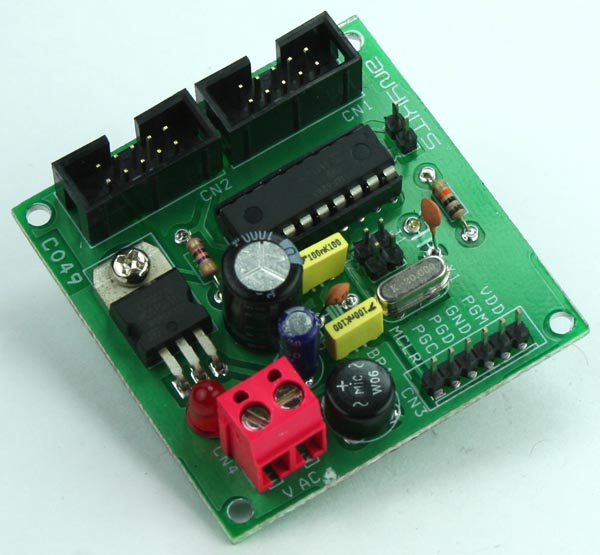
This board can be used with any of the 16F / 28 Pin PIC ICs compatible with 16F73 MCU. This kit is supplied with a PIC 16F73 MCU for development purposes.
The Clock frequency to the MCU is a 4 Mhz Crystal
This Development Board offers a ICSP connector for easy download of your code onto the MCU. Resistor R1 and Diode D1 Offer protection of Programming voltage interfering with the Supply voltage.
A 16×2 Backlight LCD helps as a displays of data in your project. PR1 controls the Contrast of the LCD.
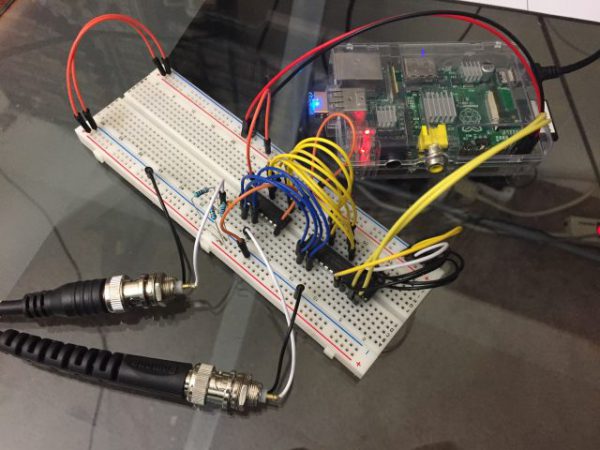
Raspberry PI RF Frequency Counter with Python Interface. The RF signal clocks a 32-bit counter (SN74LV8154) connected to a 16-bit IO expander (MCP23017) accessable to the Raspberry Pi (via I²C) to provide real-time frequency measurements from a python script.
Chrome Browser version 53 came out with a new feature: Origin Trial for Bluetooth which allows websites to use this feature and enable Web Bluetooth for all their visitors. Web Bluetooth is a new technology that connects the Web with the Internet of Things, this technology will provide a level of integration in the IoT scene that never happened before making web designers eager to get their bits out into the real world.
There is no need to install a mobile app on your smartphone to control any of your Bluetooth Low Energy (BTLE) devices anymore. Thanks to this technology, it will be easier to build one solution that will work on all platforms, including both mobile and desktop, that result to lower development costs, more open source control interfaces for various physical products, and more innovation.
To understand how that works, here’s an example of a drone controlled from a web app:
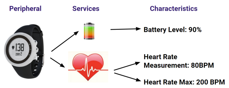
In Bluetooth Low Energy networks, devices play two roles. A device can be either a “Central” or a “Peripheral”. Bluetooth device with services that correspond to one function of the device. Each service exposes variables called characteristics that represent one parameter of the service, which can be read, written or both. Each service and characteristic is identified by a unique 16-bit or 128-bit number and they are defined by the Bluetooth SIG (Special Interest Group).
Bluetooth Low Energy: Peripherals, Services and Characteristics
How to use Web Bluetooth
In order to use Web Bluetooth, your site must be served over a secure connection (HTTPS). A secure website is becoming a requirement for a growing number of new web APIs. One way is using GitHub hosting. The implementation of the Web Bluetooth API is partially complete and currently available on Chrome OS, Chrome for Android M, Linux, and Mac.
This is the process that will be common for all Web Bluetooth apps:
Scan for a relevant Device
Connect to it
Get the Service you are interested in
Get the Characteristic you are interested in
Read, Write or Subscribe to the Characteristic
The code should be written in JavaScript. It has to scan for a device with an identified Service number, then ask for this service, ask for a specific characteristic number, and finally write the desired command. An example for hacking a light bulb and connecting it to the web via bluetooth is available here.
Although the browser is the most ubiquitous cross-platform operating system that the world has ever seen working on all platforms and systems, it could be a threat because of many malicious websites that mischief with your security. Sites ask the browser to show a list of nearby Bluetooth devices matching certain criteria, and the user either picks which to grant access to or cancels the dialog. Thus, users’ permission is the only responsible about their own privacy.
Two conflicting views are raising right now, one is for IoT enthusiasts and the other’s for security geeks. Essentially, this integration will push forward the development of new IoT applications. but it may risk users’ privacy. On the contrary, Developers are promising to minimize risks and are assuring that connection through this API will be secure and privacy-preserving. The Chrome team will end the trial in next January (2017), and after that, they expect to be able to stabilize the feature and move it closer to a general release.
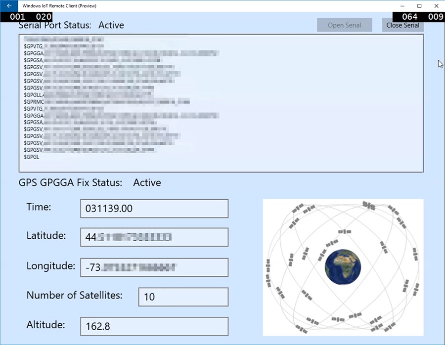
Bardaan A published a guide on hackster.io showing full instructions for developing a Windows IoT application that receives and extracts essential GPS data from a connected serial GPS module.
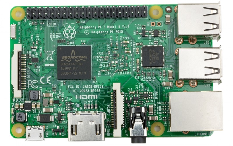
The Raspberry Pi 3 model B is a $35 single board computer with the size of a credit card. It is an improved version of Raspberry Pi 2 Model B and it features a 1.2 GHz 64-bit quad-core CPU,1GB RAM, integrated Wireless LAN, and Bluetooth 4.1 supporting Bluetooth Low Energy (BLE). The main board contains 4 USB ports, 40 I/O pins, HDMI port, Ethernet port, 3.5mm audio jack, and microSD card slot.
Raspberry Pi 3 model B
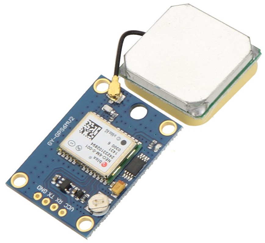
Andoer NEO-6M is a standalone GPS receiver module that implements the NEO-6M position engine developed by u-blox. It supports UART, USB, DDC (I2C compliant) and SPI interfaces and has low power consumption with high performance capabilities. NEO-6M’s strength point is that one of the received NMEA sentences is the GPGGA sentence, Global Positioning System Fix Data, which provides essential fix data.
Andoer NEO-6M GPS Module
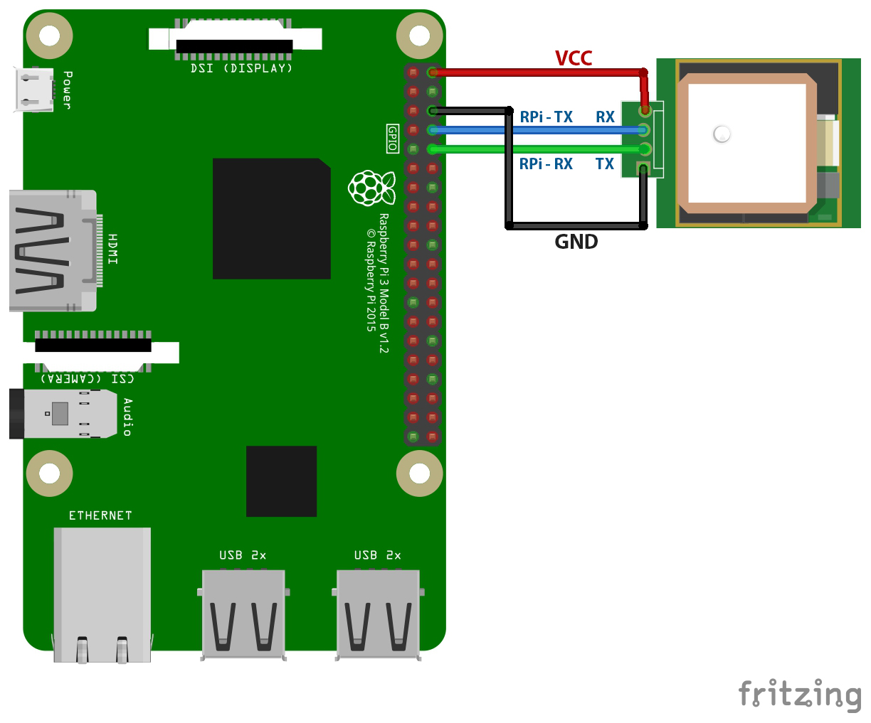
The received GPGGA sentence will be send by Raspberry Pi to the application which processes it and extracts the essential information such as time, geographic coordinates, and altitude, and eventually displays them on a GUI with the connection status .
The GPS receiver must be connected to the Raspberry Pi as shown in the figure:
The source code with the detailed tutorial can be reached here.