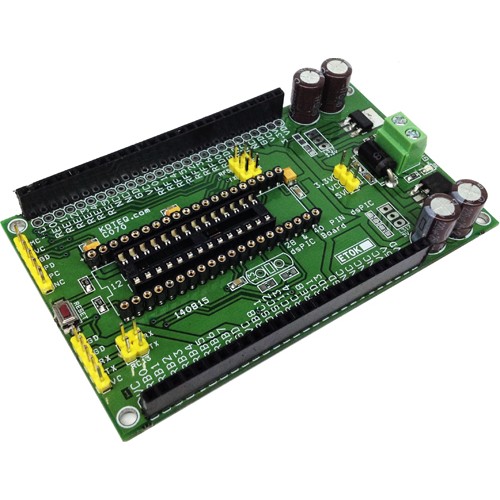
The dsPIC Development Board is a development and evaluation tool that helps create embedded applications using dsPIC30F Digital Signal Controllers for motor control family. Sockets are provided for 28 and 40-pin devices in the motor control family.
The dsPIC Development board has been designed mainly for Motor dsPIC30F4011 Digital Signal Controller in the 40-pin motor control socket and dsPIC30F4012 28 Pin digital signal controller, the board can also be used with other dsPIC ICs. Board provided with 3.3V and 5V regulator, crystal oscillators and a programming connector. In addition, the board is populated with dual header connector for all I/O, reverse supply protection diode, onboard 3.3V & 5V LED, Screw terminal for supply input, push button switch for reset, 6 pin header connector for programming, serial communication header connector, jumpers for multi serial communication option , electrolytic capacitor for filters. Optional provision for LM317T TO220 Regulator for 3.3V and 5V and Jumper for 3.3V or 5V power supply selection to power up the dsPIC.
Specifications
- Dual sockets for 28 and 40-pin PDIP devices
- On Board Reverse Supply Input Socket
- Supply Input 7V to 15V ( LM7805 & LM1117-3.3V) Regulators
- Optional Supply Input 7V to 36V DC If Populate LM317T TO220 IC
- Sample application programs and project files available from microchip website for supported dsPIC30F devices
- dsPIC30F4011 40-pin PDIP and dsPIC30F4012 28-pin PDIP
- On Board Dual 5V & 3.3V regulator provided to full fill low and TTL supply requirement.
- On Board programming Header Connector
- On Board 3.3V & 5V Power LED
- Jumper to select 3.3V or 5V going to dsPIC
- Jumper for 2 UART Port or CAN selection
- Controller Area Network (CAN) interface
- 1 push button for Reset
- Access to all pins on the dsPIC30F device sockets via Dual headers
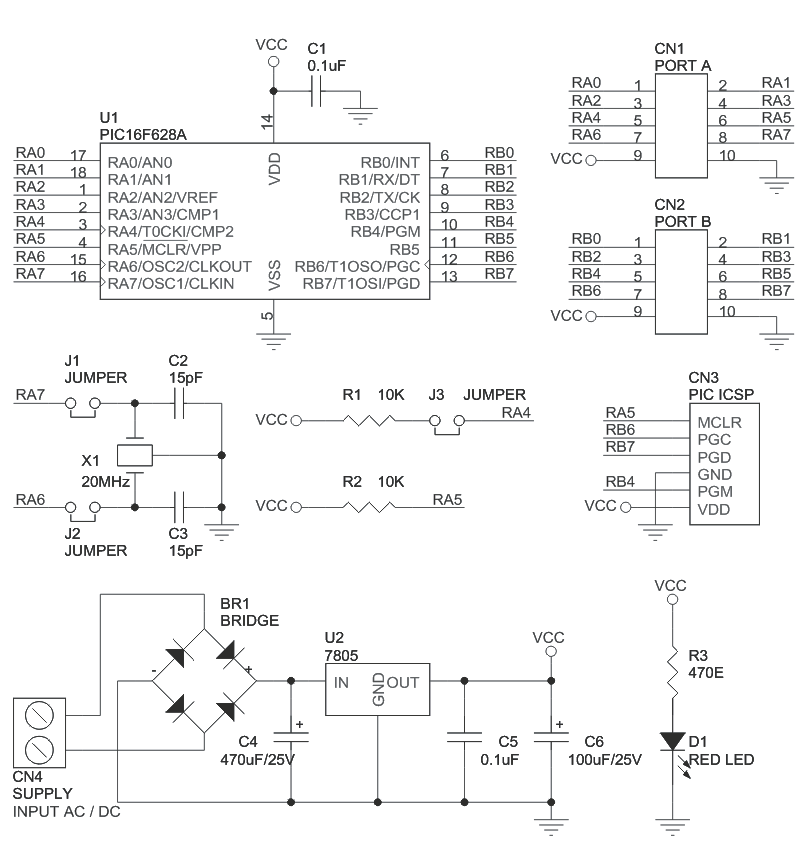
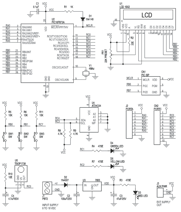
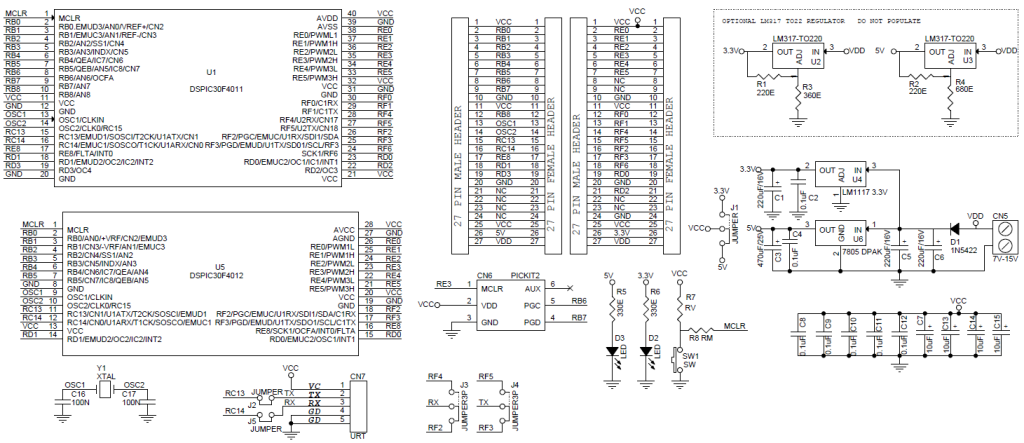
Schematic
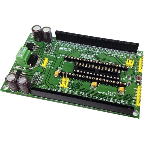
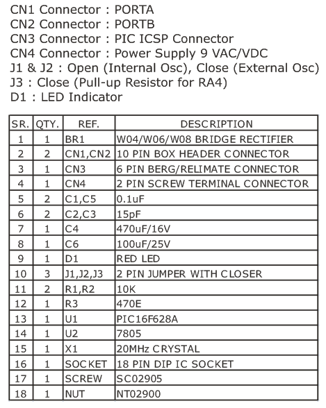
Pinout

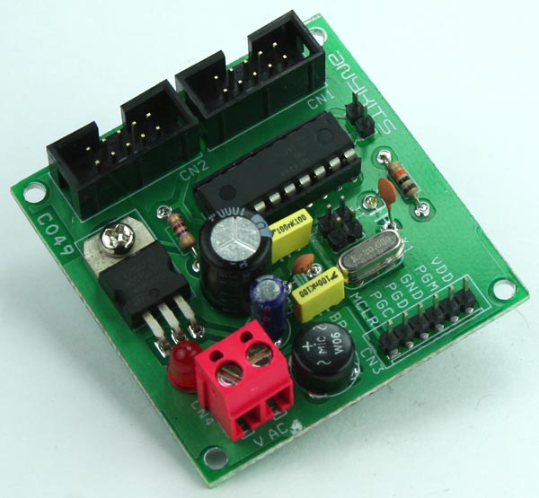
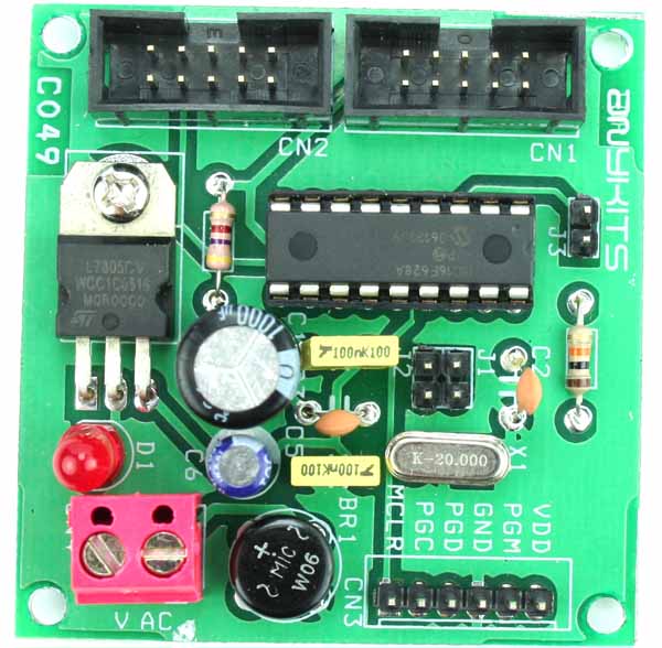
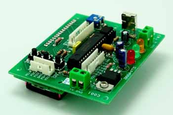
Photos