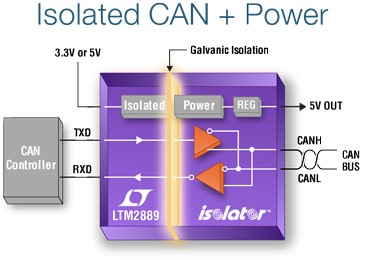
The LTM2889 is a fully ISO 11898-2 compliant CAN (controller area network) μModule transceiver and isolator that guards against large ground-to-ground differentials and common mode transients in 3.3V or 5V applications. In practical CAN systems, ground potentials vary widely from node to node, often exceeding the tolerable range, which can result in an interruption of communications or destruction of a transceiver. The LTM2889 separates grounds by isolating the CAN transceiver using internal inductive isolation. It implements multiple levels of protection to significantly improve system reliability, including 2,500VRMS of galvanic isolation, ±60V bus voltage fault tolerance, greater than 30kV/μs common mode transient immunity, and ±25kV HBM ESD protection. The LTM2889 requires no external components, ensuring a complete and robust μModule solution for isolated serial data communications.
LTM2889 – Isolated CAN FD µModule Transceiver and Power – [Link]
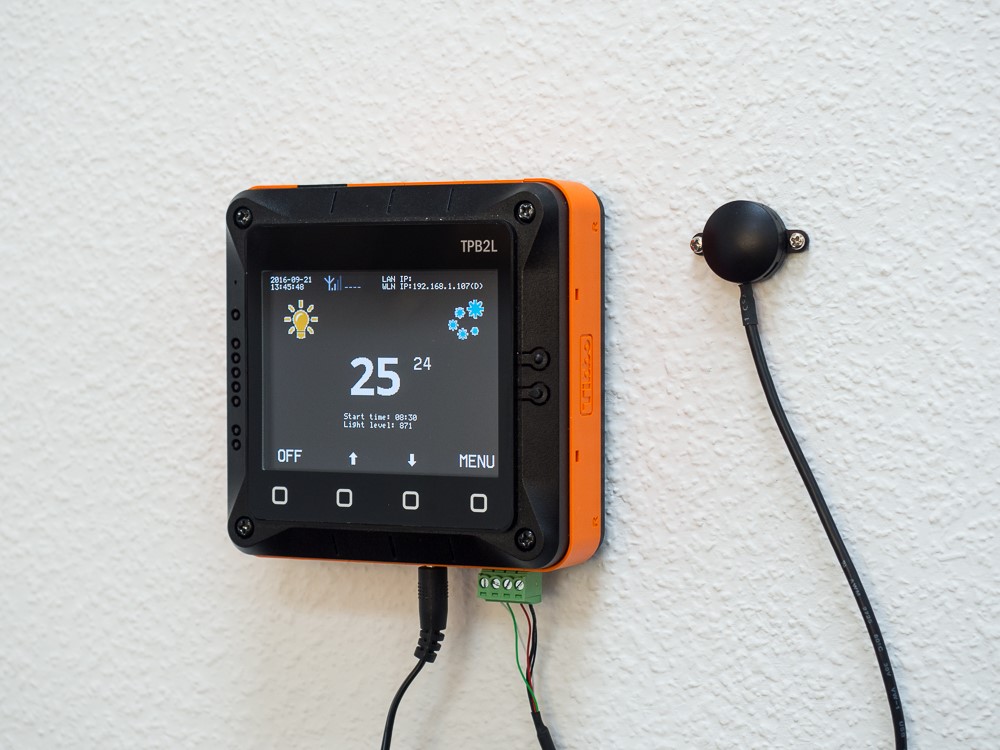
The app allows you to manage traditional air conditioners that are controlled through infrared remotes. Designed for the office environment, the app relies on the ambient brightness (measured by Tibbit #28) to determine whether the aircon should be running or not. In the office setting, no lights = no people = no need for the aircon to work.
Air conditioning is a consumptive business while air conditioners are big-ticket to run. In general, AC systems, older ones, in particular, do not have any real temperature feedback. You set the temperature on your remote, but alas, it has absolutely nothing to do with the actual temperature in the room. Even when it gets colder outsides, many aircons keep blasting cold air into your space. As a result, you have to constantly readjust the temperature as needed for optimal comfort throughout the day. Continue reading “Tibbo Project System-based Aircon Controller Application”
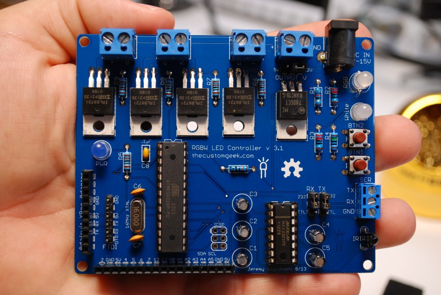
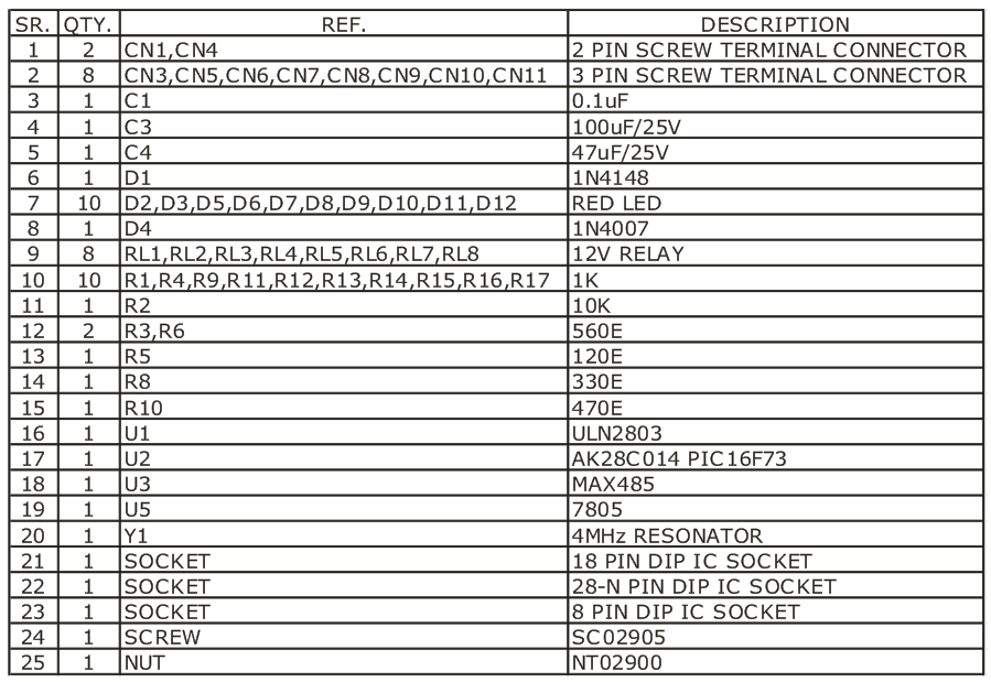
This project helps you control 8 relays using RS485 link with the help of a PC. This kit can effectively convert a standard PC to a powerful PLC ( programmable logic controller ). At the PC end , you will need to use our RS232 to RS485 Interface – C020 or any other suitable RS232 to RS485 Converter.
The project can offer a low-cost serial relay contact interface, easy to use with Visual Basic, Basic, C, Labview, Testpoint, or other high level languages that allow access to a serial port.
You can simply use the accompanying software provided with this project or issue control commands using any popular Terminal Port software available on the net.
The Serial port on the computer should be configured to 2400 baud – 8 bit words – 1 stop bit – no parity
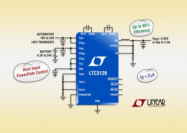
LTC3126 is a 2.5A, 2.4V to 42V input, synchronous step-down switching regulator with integrated dual input PowerPath control. Its power stage topology enables operation from either of two independent power sources, with seamless, internally controlled transitions between inputs to ensure a stable output voltage during hot-plug and power source disconnect events.
Steve Taranovich discuss about various ways to enhance Li-Ion batteries safety.
Typically, Lithium-ion batteries are safe and reliable. Just think about the $28B market they had in 2013 with a relatively small amount of fires and explosions. But every fire and explosion incident has the potential to cause a loss of life or serious personal injury (Not to mention the collateral material damage and cost).
However, the severity of each occurrence cannot be understated, as any fire or explosion has the inherent potential to result in the loss of life or cause serious personal injury. The collateral material damage and associated costs further highlight the need for proactive safety measures.
In light of the potential risks associated with Lithium-ion batteries, implementing a comprehensive Fire watch service becomes paramount. Incorporating regular Fire Watch protocols as a preventive measure can significantly mitigate the risks posed by these incidents. By conducting diligent Fire Watch, organizations can ensure early detection of any signs of overheating or malfunction, allowing for swift intervention before a situation escalates into a hazardous event.
This proactive approach not only safeguards lives and personal well-being but also protects against material damage and the consequential financial burdens that may arise from fire or explosion incidents involving Lithium-ion batteries.
Lithium-ion battery fires: 7 solutions for improved safety – [Link]
Although the industry of professional satellite navigation systems is limited to experts and large companies, Amungo Navigation is working towards bringing this industry to individual developers, small companies, and startups through its new open source platform “NUT4NT”.
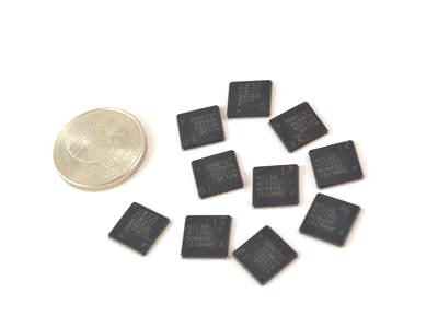
NT1065 chip
NUT4NT is a development board which implements NT1065 chip with USB 3.0 interface. NT1065 is a Global Navigation Satellite System (GNSS) receiver designed by NTLab, a fabless microelectronic company. It is the first low-cost low-power RF front-end solution in the world. It also has 4 channels supporting all GNSS systems and bands.
GNSS receivers are electronic devices that receive and process signals from a GNSS satellite. These signals used to provide information about receiver’s position,velocity, and time.
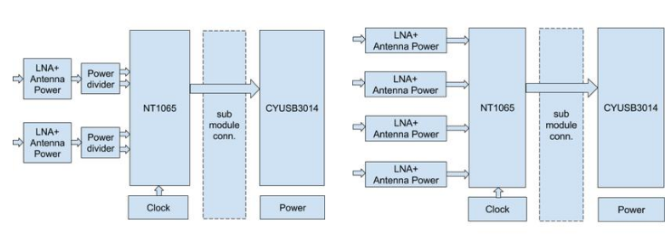
NUT4NT has two different working modes. The first uses dual inputs and acts as a centimeter level precision positioning tool, without the need of high quality antenna. The other mode uses the four inputs and provides an array antenna processing system to simply reduce interference and noise.
Dual Inputs Mode (Left) – Four Inputs Mode (Right)
Samples transfer – continuous full stream, from 20 to 100 Mbytes/sec
Power: 5V @ 0.5 A from USB or external adapter
Size: 70x50x20 mm (early board) / 77x122x25 mm (single board)
All GNSS systems: GPS, GLONASS, Galileo, BeiDou, IRNSS and future
All GNSS band: L1/L2/L3/L5, G1/G2/G5, B1/B2, E1/E5 and future
Four-channel synchronous reception for antenna array processing
Signal dumper (grabber) software
Spectrum analyzer software
NT1065 configuration software
Supports libusb API
Supports native Cypress driver API
Software for Windows, Linux, and potentially all other OS’s with libusb
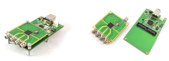
There are two options of NUT4NT boards, the Early Board and the Single Board.
Early Board is for $399 and there are only limited boards to order through the crowdfunding campaign page. It consists of two separated boards: the base board, which has the USB 3.0 controller, and NT1065 submodule board.
Single Board will be available later as a future plan, and it is said to have only one board instead of two.
NUT4NT Early Board
NUT4NT is an open source project. Software sources are available on github and the hardware’s documentation will be available soon.
More information and details about the product with many accessories are reachable on the product crowdfunding page.
“NanoEngineers” research group at Iowa University have been devoting efforts to use graphene and its amazing properties in their sensors and other technologies. Graphene has many extraordinary properties. It is about 100 times stronger than the strongest steel. It conducts heat and electricity efficiently and is nearly transparent.
Inspired by some recent projects about using inkjet printers to print multi-layer graphene circuits and electrodes, “NanoEngineers” have been working to move this research further by using the technology for a larger scale flexible, wearable and low-cost electronics. But there was some hurdles in improving the graphene conductivity after being printed and this process may damage the printing surface, such as papers, because of the high temperature or the use of chemicals.
Eventually, these engineers have led development of a laser-treatment process that allows them to use and improve printed graphene for electronic circuits and electrodes, even on paper and other fragile surfaces. The technology is said to show tremendous promise for a wide variety of fields including wearable sensors and thin film transistors with the ability of large-scale manufacturing.
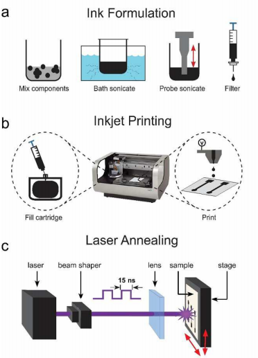
It’s a three step process:
Graphene ink formulation: single layer graphene (SLG) powders were mixed with solvents and binders, bath sonicated, probe sonicated, and syringe filtered in order to produce a jettable graphene ink.
Inkjet Printing: The resultant graphene ink was syringed into the printer cartridge of a Dimatix Materials Printer and ejected via a piezoelectric nozzle in the subsequent printing process.
Laser Annealing: A pulsed-laser processing of the electrodes using a Nd:Yag laser.
Formulation, Printing, and Treatment, Source: Original Paper
The engineers were able to remove ink binders and reduce graphene oxide by developing a computer-controlled laser technology that selectively irradiates inkjet-printed graphene oxide, Transforming the inkjet-printed graphene into a conductive material capable of being used in new applications is a huge breakthrough in nanotechnology.
More details are available at this paper on NanoScale journal.
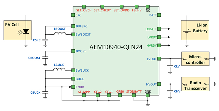
AEM10940 is a power management IC designed by e-peas to store power from photovoltaics (PVs) cells and thermoelectric generator (TEGs) into rechargeable power sources, such as Li-Ion batteries and thin film batteries. At the same time, it supplies the system with two different regulated voltages, the charging voltage and the system supply voltage.
e-peas is a startup based in Liège, Belgium. It works towards solutions to extend batteries life-time for IoT applications, by increasing the amount of harvested energy and reducing power consumption for each element in the system.
AEM10940 Block Diagram
The AEM10940 features are:
Ultra low power start-up, which gives it the ability to operate with just 380 mV input voltages and 1 μW input power.
Ultra-low-power Boost regulator, whit operates with input voltages in a range of 100 mV to 2.5 V.
Integrated Low Drop-Out (LDO) regulator, drives a microcontroller at 1.8 V with up to 10 mA load current at low voltage supply, and drives a radio transceiver at configurable voltage from 2.2 V to 4.2 V with 80 mA load current.
Programmable overcharge and overdischarge protection
Suitable for any type of rechargeable battery or supercapacitor
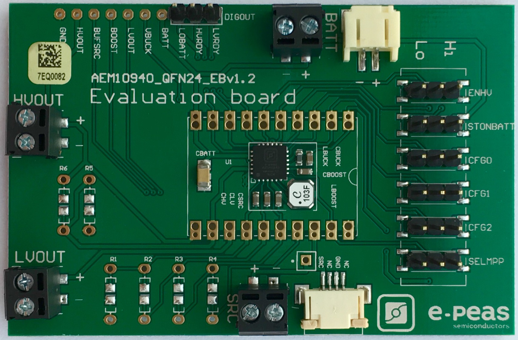
The AEM10940 Evaluation Board
e-peas introduces AEM10040 as an evaluation board that provides a laboratory-like environment for testing and analysing. It also simplifies the connections with power sources, storage elements, and the different loads. However, the evaluation board is not suitable for end-user applications.
This project helps you control 8 relays using RS485 link with the help of a PC. This kit can effectively convert a standard PC to a powerful PLC ( programmable logic controller ). At the PC end , you will need to use our RS232 to RS485 Interface or any other suitable RS232 to RS485 Converter.
The project can offer a low-cost serial relay contact interface, easy to use with Visual Basic, Basic, C, Labview, Testpoint, or other high level languages that allow access to a serial port.
You can simply use the accompanying software provided with this project or issue control commands using any popular Terminal Port software available on the net.
The Serial port on the computer should be configured to 2400 baud – 8 bit words – 1 stop bit – no parity
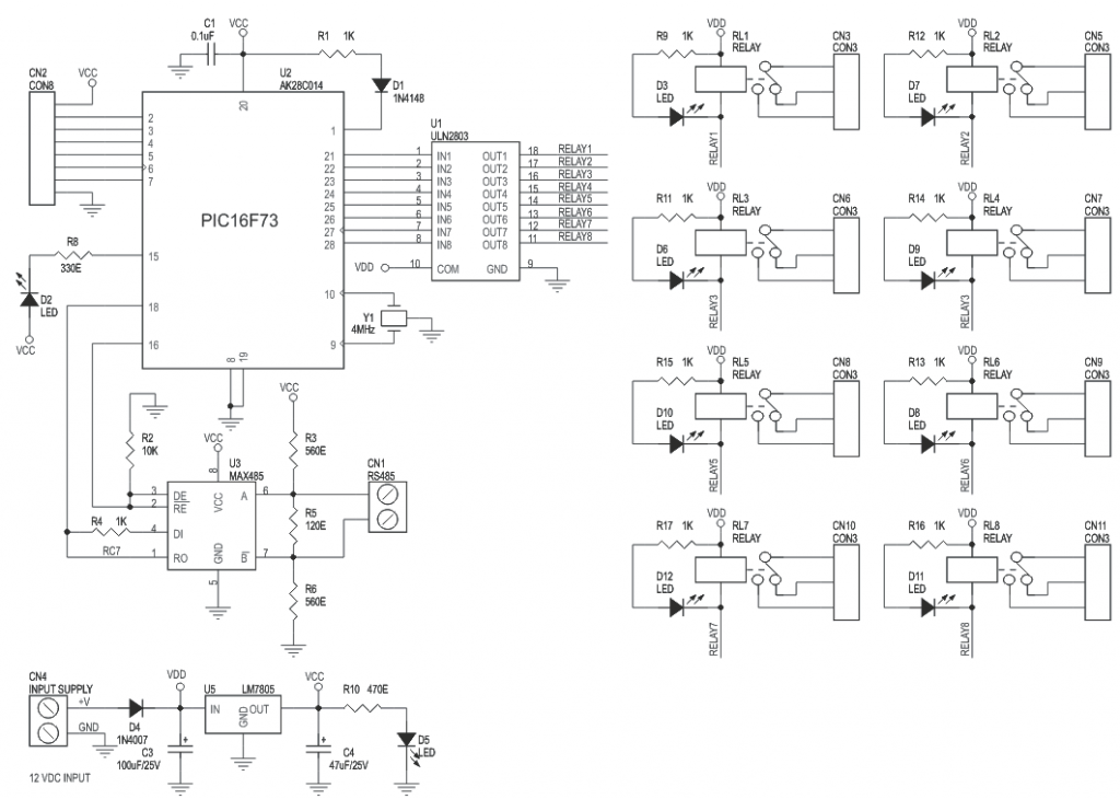
RELAY OUTPUT COMMAND SUMMARY
RBnc – “RB” preamble, n – Relay number (1 to 8) and c – set/reset (1 – set, 0 – reset)
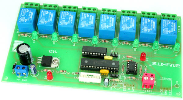
RS485 cable connects at CN1 connector. The setting or resetting of the relays is indicated by the associated LED’s close to them. LED D2 blinks to indicate a valid command received. LED D5 is the Power On Board Indicator.
Please refer to the schematic diagram for the configuration of this board.
With RS485 Controlled 8 Relay Board you can control up to 8 SPDT (Single Pole Double Throw) relays using a simple RS485 protocol.
Features
Up to 8, 12V SPDT relay control
Industry standard relay drive IC – ULN2803
Data received indicator LED
LED indicator to display relay state
Power-On LED indicator
Onboard regulator IC
Screw terminal type connector for easy connection of all wires to the PCB
Simple RS485 Protocol
Can be controlled either by a microcontroller board or via PC using suitable RS232 – RS485 converter
Diode protection against reverse polarity connection
NC-C-NO pin outs from each relay into a screw terminal connector