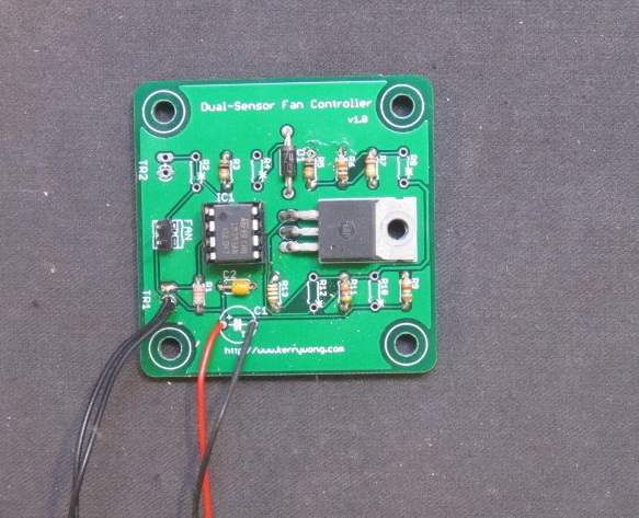
To make the design more useful, one channel is marked as optional (see components with * on the silkscreen) so that you can build either a single sensor fan controller or a dual sensor one. With two sensors, the control signal is or’d with both of the sensor input and if either side of the temperature exceeds a predefined threshold the fan will be turned on. This is useful in situations where power devices from multiple channels share the same heat sink
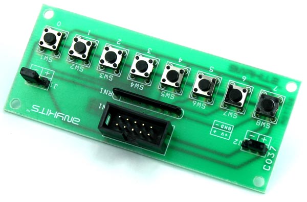
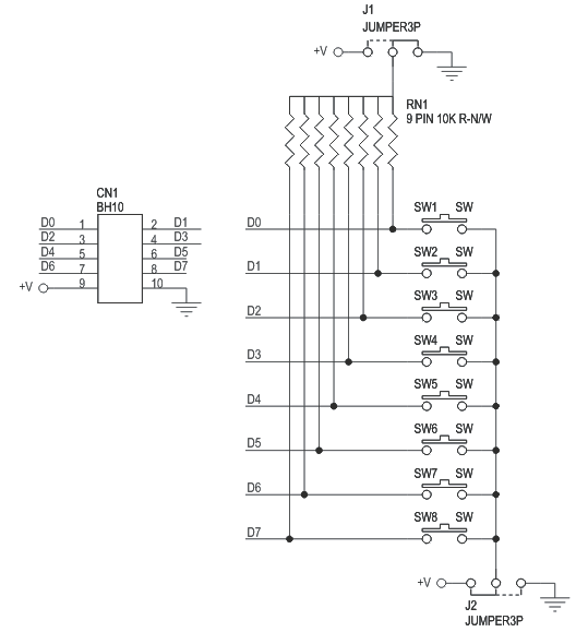
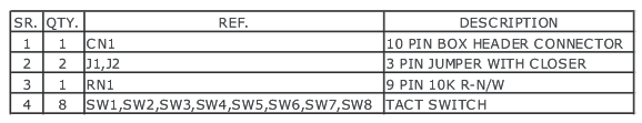
8 Tactile Switch Input Board is a simple PCB offering easy connection of a standard 10-pin Box Header connector to 8 small type Tactile Switch with a jumper selectable pull-up / pull down of resistor network connected in parallel. Easy interface with PIC and Atmel Development board published on our website.
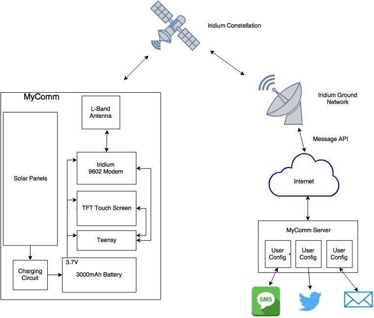
Never before have we been so incredibly connected to one another than today; thanks to the prevalence of internet and mobile data networks. But the dimension of this connected world is finite and ends not far beyond the outermost cell phone tower. John Grant wanted to be connected to his friends and family all the time and from everywhere. So he planned to build MyComm, a portable satellite messaging system that allows him to send text messages from anywhere on Earth.
MyComm communication network
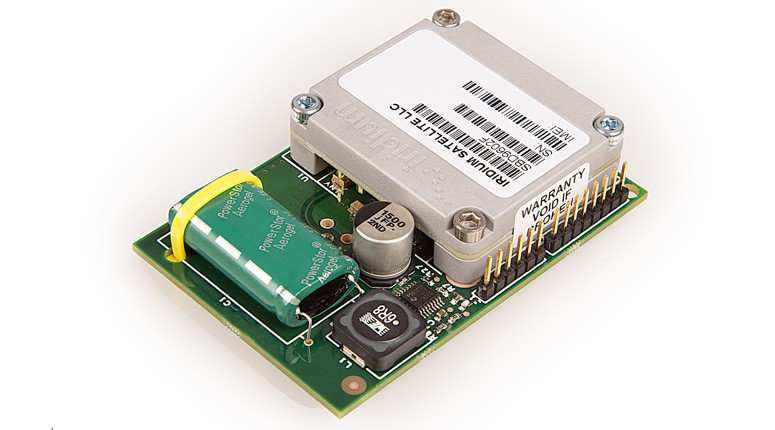
The MyComm project consists of two parts: the MyComm Handheld and the MyComm Server. The MyComm Handheld is a standalone device that features a 2.8” TFT LCD touch screen user interface and is capable of running on solar power. The heart of this project is the RockBLOCK Mk2, a satellite modem with an Iridium 9602/3 Transceiver, which allows two way communication with the MyComm Server over the Iridium Satellite Network using the Iridium Short Burst Data (SBD) service. The SBD is a bandwidth-limited messaging system, and therefore, the transmitting and receiving packets are limited to 340 bytes and 270 bytes per message, respectively. With 66 operating satellites, the Iridium satellite network works far beyond the reach of WiFi and GSM networks and allows transmission of information from any point on Earth, including the polar regions. The MyComm project uses a Teensy 3.1 micro controller module for handling the user inputs and text messages, as well as for controlling the satellite modem. Because Iridium operates in the microwave L-band, MyComm requires an unobstructed line-of-sight view of a satellite is for reliable data communication. John has already submitted MyComm to the 2016 Hackaday Prize contest and is planning to run a Kickstarter campaign in ear future to launch this project into the market.
The potential competitor of ESP8266 wifi module will be available next week for just $2! Pine64, the manufacturer of the first $15 64-bit single board computer, is now preparing to launch “PADI IoT Stamp” RTL8710AF module.
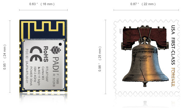
This module has the size of the stamp, a small 24mm x 16mm package with powerful specifications compared to its price.
The Size Compared To A Stamp
Realtek RTL8710 could be a good alternative thanks to its ARM Cortex-M3 processor @ 166 MHz, a little more user memory (48KB), audio support, and faster WiFi performance.
Here are the specifications of the module: SoC: Realtek RTL8710AF ARM Cortex-M3 @ 83 MHz with 1MB ROM, 512KB RAM, and 1MB flash Connectivity: 802.11 b/g/n WiFi @ 2.4 GHz – 2.5 GHz (2400 MHz – 2483.5 MHz) with PCB antenna; Station / SoftAP / SoftAP + Station modes Expansion headers: 22 half-holes with
Up to 1x SPI @ 41.5 Mbps max
Up to 3x UART with 2x up to 4Mbps, 1x @ 38400 bps
Up to 4x PWM
Up to 1x I2C @ 3.4 Mbps max
Up to 19 GPIOs including 10 supporting interrupts
Power Supply: 3.0 to 3.6V (3.3V recommended) Power Consumption: 87 mA typ. @ 3.3V using 802.11b 11 Mbps, +17 dBm; 0.9 mA light sleep; 10 uA deep sleep Dimensions: 24 x 16 mm Temperature range: -20 ℃ ~ 85 ℃
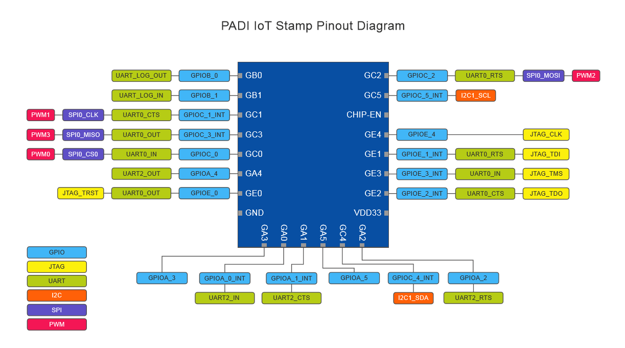
PADI IoT Stamp Pinout Diagram
With the ability to program the module via IAR, openOCD, and/or J-Link, it also supports firmware updates via UART, OTA, and JTAG.
The processor is said to run FreeRTOS operating systems, which happens to be the one also used in Espressif ESP8266 and ESP32 SDKs. It will also support ARM® mbed™ as a future plan.
A group of developers in Elektor Labs have modified a high power wireless power transfer project, which originally developed byWürth Elektronik eiSos GmbH & Co. KG, an electronic and electromechanical components manufacturer in Europe, in an attempt to come up with an easy-to-achieve solution for wireless power transfer of more than 100 Watts without using any kind of controller or programmed elements.
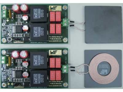
The Original Transmitter and Receiver Circuits
The same circuit is used in both transmitter and receiver circuits. It is based on a resonant converter which generates a constant frequency according to the LC parallel resonant circuit. The resonant converter, also known as Zero Voltage Switching (ZVS) oscillator, has no power-loss elements and provide high efficiency response with up to 200 Watts of energy.
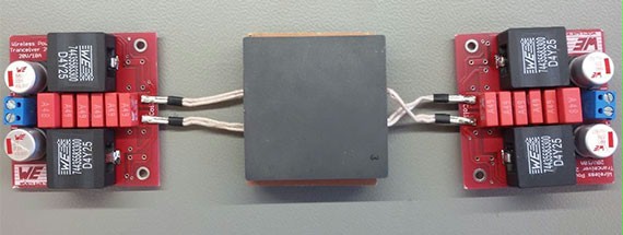
The Modified Transmitter and Receiver Circuits
In the modified version, the gate driving circuit were replaced with a faster one which uses a separate power supply. Also a protection circuit consists of a PTC resettable fuse was added using a high-side current monitor IC, this will protect the whole circuit from damage by shutting down the converter.
This version delivers up to 50 Watts with 88% efficiency for 12-24 V supply voltage.
More details about this project are available here, including the bill of materials BOM, schematics, and how circuits work.
More information about original circuits are available here.
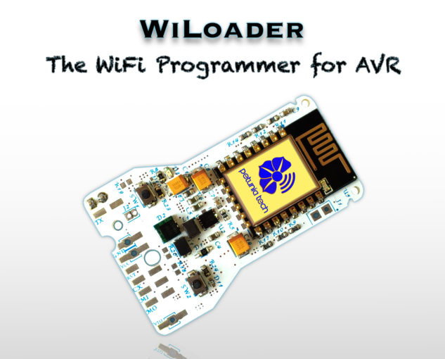
The new generation of programmers that use WiFi instead of cables. Program, control and monitor Robots, AVR and Arduino over WiFi.
Have you ever thought of programming wirelessly ? WiLoader is the answer. But HOW ???? WiLoader easily connects to your WiFi network, then you can program your AVR, Arduino boards, Robots and other targets like them. It doesn’t need any kind of cable for computer connection, especially those huge old USB ones. Because it employs WiFi, even your smartphone can be used to configure, communicate, control and monitor your targets via a WiFi-UART bridge.
WiLoader : The WiFi Programmer for Arduino & AVR – [Link]
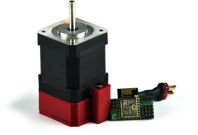
WiFi controllable motors for your many projects. An Open Source platform that anyone can use.
Using our motors is as simple as joining your motors network (or adding the device to an existing network) and controlling it with any of our apps, its built it webpage, or just raw JSON packets. Our motors are made to be both a solution for someone not skilled enough to set up stepper and servo motors, and for experts who want a less messy way to implement motors. Our hardware and software are both on github, and our board was made specifically to be compatible with the free version of EagleCad.
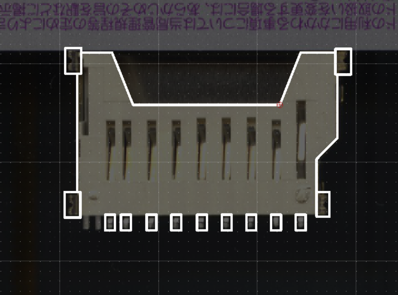
Jan @ jasiek.me decided to use a flatbed scanner to trace out a footprint in KiCad. [via]
Some time ago I sourced a number of very cheap SD card sockets from China for a hobby project I was working on. Sadly, when it came to PCB design, I couldn’t find the footprints for this particular socket anywhere – the part being a proprietary invention of the factory rather than a cheap knockoff of a reputable brand like Amphenol or Molex for which drawings are readily available off of snapeda.com.
Creating footprints in KiCad using a scanner – [Link]
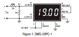
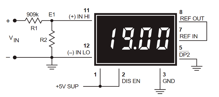
Scaling large values to be fed on limited input digital meters, application note from Murata. [via]
It is oftentimes necessary to attenuate “large” input signals down to a level that more closely matches the input range of a selected meter. For example, suppose the signal to be measured is 19 Volts, and the input voltage range of the available meter is 2 Volts (the preferred model for any attenuation circuit). Obviously, the “raw” input signal voltage is much too high for a ± 2V meter to measure directly and must first be attenuated.
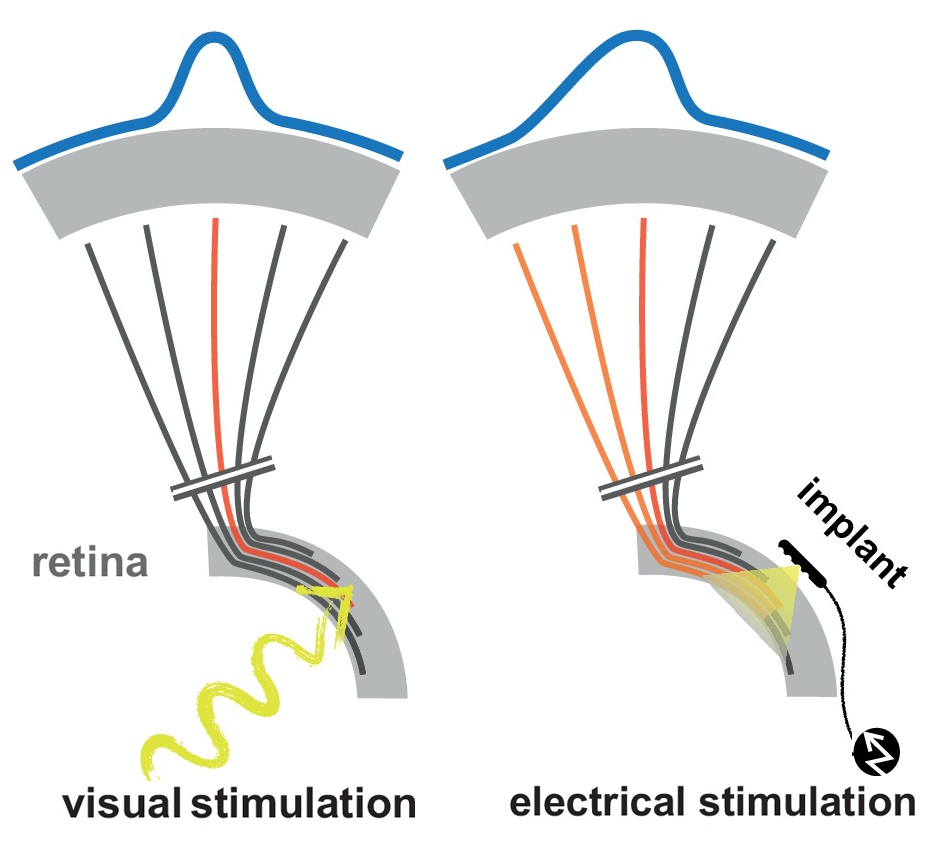
Denis Meyer @ elektormagazine.com discuss how the researchers improved the resolution of retinal prostheses.
A retinal prosthesis substitutes for the photo-receptor cells of the defective retina. It’s composed of a camera carried in spectacles; electronics that processes the camera information; and a matrix of microscopic electrodes implanted in the eye in contact with the retina. These electrical signals are carried to the brain by the optic nerve. With such implants, totally blind patients can recover some visual perception in the form of spots of light called phosphenes. Alas, these are not clear enough to recognize faces, read or move around.
Improvement in the resolution of Retinal Prostheses – [Link]