Welcome to the 4th post of the “Exploring Eagle CAD ULPs” series. Every week we will publish a new post about one useful ULP in Eagle CAD.
“ULP” User Language Program is a plain text file which is written in a C-like syntax and can be used to access the EAGLE data structures and to create a wide variety of output files. You can consider it like a plug-in for Eagle.
You can reach the posts published in this series using the following link.
In this post we are going to explore a ULP called ‘renumber-part.ulp’. This ULP is designed to renumber the parts used in the schematic automatically.
When you work on a design, you always need to add and delete components here and there, and if you work on a big design you will find that the numbering of parts are not in order. For example, if you have 30 resistors in the schematic, then the numbering could start from R10 and have some discontinuity in number sequence, let us say from R15 to R20 then it continues with R21. It’s more handy to have your parts numbered correctly starting from number one without any interruptions. This is useful for BOM organization and also for maintenance guys.
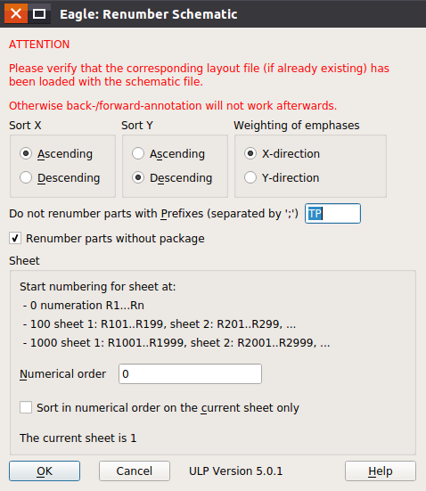
This ULP has a GUI to select the options before running it. You can choose to start numbering from 0,0 axis if ‘SortX’ and ‘SortY’ are chosen to be ascending or from the highest point if you choose both of them to be descending.
Another option is the weighting of numbering (i.e.which will be numbered first) by the direction of X axis or Y axis. This ULP comes with Eagle CAD, so you don’t need to download and add it manually. You can run it from the toolbar -> tools -> renumber parts.
That is all for this time. See you on next post.