This application example shows how to connect and use RGBW LED stripe with TPS hardware platform. The main difficulty is that LEDs have their own color generation circuit inside. New FPGA Tibbit #57 can generate fast PWM signal, which is needed for proper LEDs operation. Also, the topic shows the main advantage of FPGA technology. It allows the user to create any external interface, which will be easily connected to the TPS platform.
Test application for the FPGA Tibbit in the smart LED controller configuration – [Link]
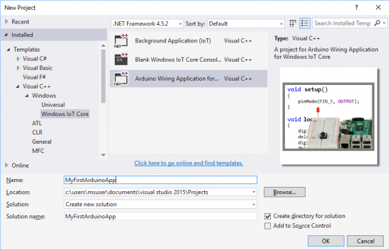
Last year, Arduino and Microsoft announced a strong partnership and Windows 10 became the world’s first Arduino certified operating system. This partnership made the creation and innovation much easier with the hardware capability of Arduino and the software capabilities of Windows.
Early this month, Arduino Wiring became a new programming language for Windows 10 IoT Core besides C#, C++, Visual Basic, JavaScript, Python and Node.js, which means that developers are now able to run Arduino Wiring sketches on all supported IoT Core devices including Raspberry Pi 2 and 3.
The popularity of Arduino in the makers’ community alongside the simplicity of using and programming its boards maybe were the main reasons for this step.
Installing and setting up may differ between devices, but all information and getting started guides for users are available online on Microsoft website, and here are the links:
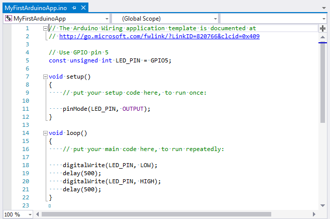
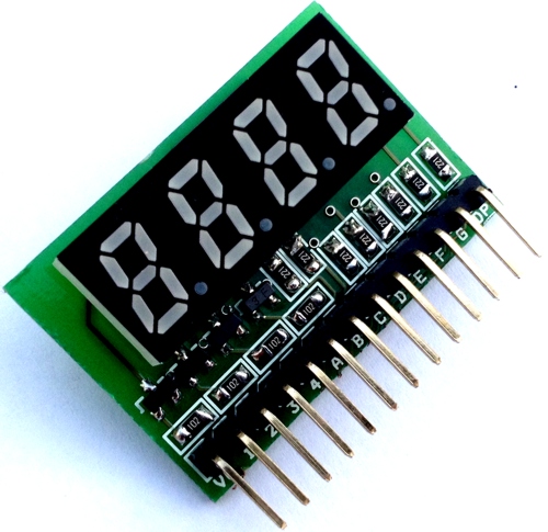
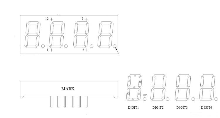
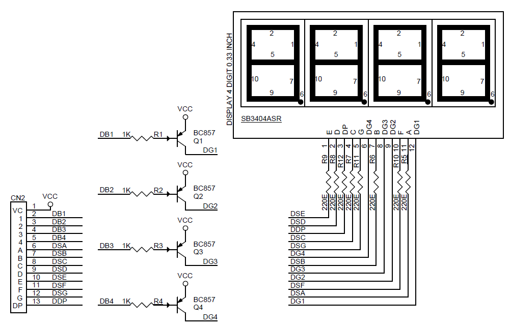
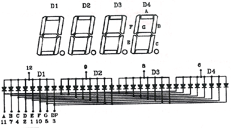
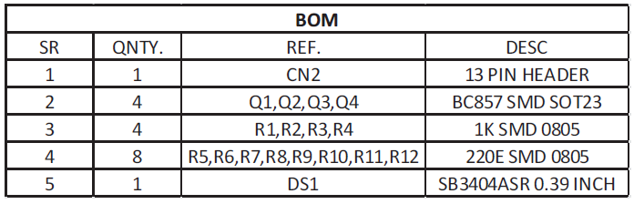
7 Seven segment multi-plexed display is tiny board that has been designed around Common Anode 4 digit Display, Display has 12 Pins. The board is provided with current limiting resistors on all LED segments and 4 PNP Transistors to drive 4 digits, the project is ideal for easy micro-controller interface with 13 pin Header connector. The Board supports 3.3V as well 5V TTL interface.
4 Digit MultiPlexed 0.33 Inch 7 Segment Common Anode Display – [Link]
A radar system uses high frequency radio waves for object detection. A high-power RF pulse is transmitted into space and its echo reflected off from an obstacle is recorded. By computing the time elapsed between the transmitted and reflected pulses, and knowing that the electromagnetic wave propagates at a constant speed of light, the radar computes the distance of the obstacle. Because the speed of radio waves is so high, the time lapse is usually very small, and therefore requires sophisticated electronics for range detection. The time lapse would be easier to detect if the waves with lower propagation speeds were used, for instance, sound waves that travel at a much slower speed (~ 340m/sec in air) than light.
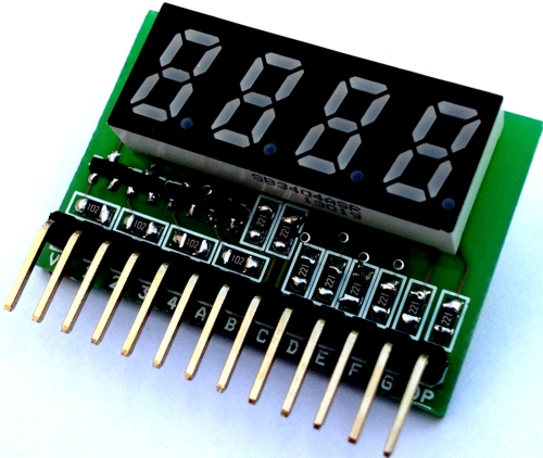
Dejan Nedelkovski from How To Mechatronics illustrates the principle of radar using ultrasonic sound waves. In his project, he used an HC-SR04 ultrasonic ranging sensor module for measuring distance to an object, similar to the echolocation technique used by mammals like dolphins and bats. The HC-SR04 is a fully-integrated module with onboard transmitter, receiver, and control circuit. It can measure an object distance ranging from 2cm – 400cm with an accuracy of 3mm. The HC-SR04 sensor is mounted on a servo motor for scanning the surrounding. An Arduino board is used to control the angular position of the servo during scans. The echo data output from the ranging sensor is received by Arduino and is sent to a computer along with the angular positions along the scan through a USB port for post processing.
Arduino radar using sound waves
On the computer side, a PC application was developed using the Processing platform to retrieve the radar echo data, combine it with the angular position data, and visualize the radar signature on the screen. Check out the following video to see this radar in action.
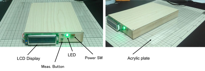
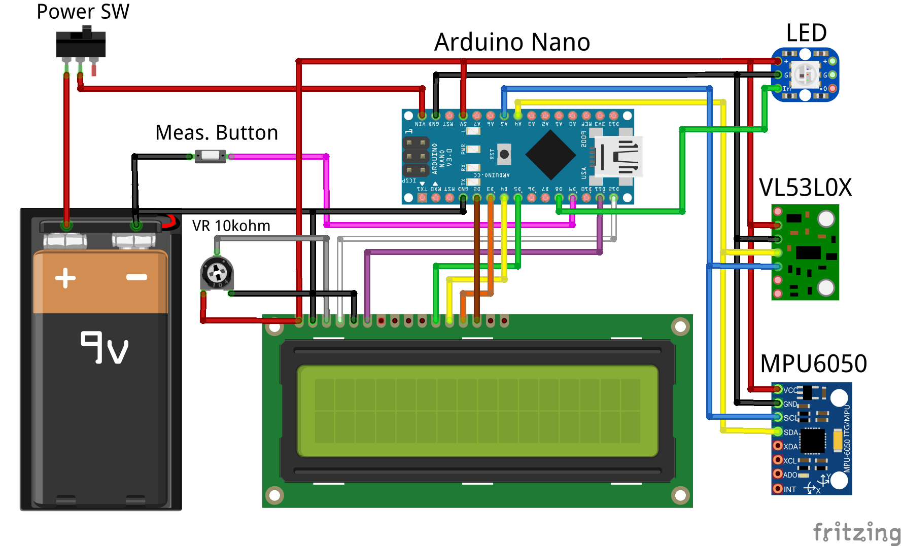
Usually, when measuring a child’s height at home, a mark is drawn on the wall then the height is measured using a measuring tape. This process is not always easy and it may has low resolution. In an attempt to simplify this procedure, a new project was developed using an Arduino and a distance sensor.
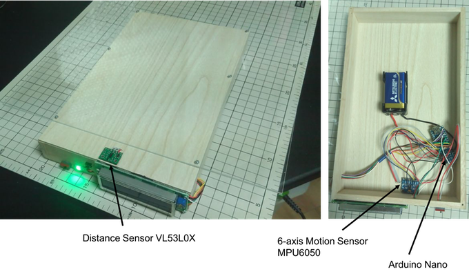
The main parts which were used in this project are:
Arduino Nano, the microcontroller which will read sensor’s values and display the results on the screen.
MPU-6050, 3 axis gyroscope with 3 axis accelerometer
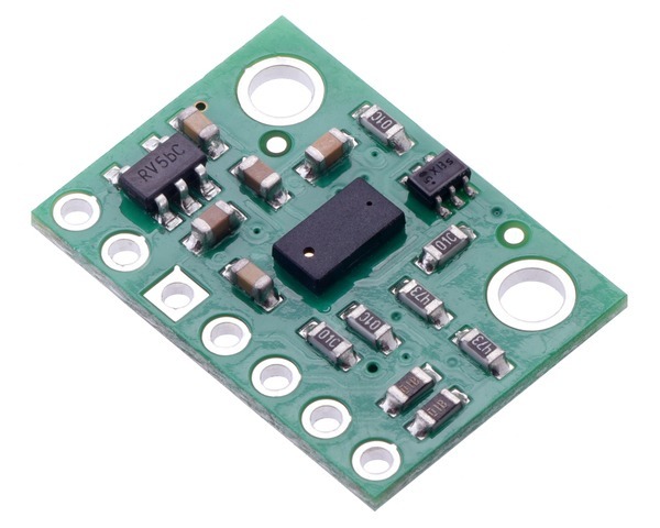
VL53L0X is a laser-ranging sensor that uses Time Of Flight (ToF) measurements of infrared pulses for calculating the distance of the facing surface. It can measure distances up to 2 meters with a resolution of 1 mm. This sensor works over an input voltage range of 2.6V to 5.5 V, and the measured values can be read through an I²C interface.
VL53L0X Sensor – Image courtesy of Pololu
To get the best result, Vl53L0X must be attached on the bottom of the box as shown in this figure.
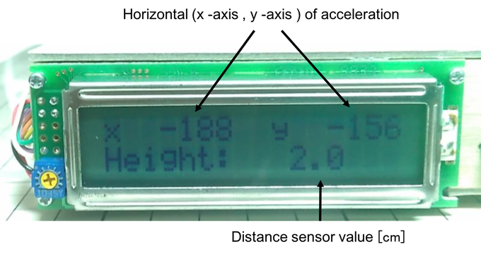
MPU-6050 is a low power, low cost, and high-performance motion tracking device, it contains 3-axis gyroscope and a 3-axis accelerometer with an onboard Digital Motion Processor (DMP™) which can be programmed with firmware and is able to do complex calculations with the sensor values and uses I²C interface. This sensor is used here for detecting the horizontal direction and for measuring X and Y axis acceleration.
This project has two working modes, Normal Mode and Measurement Mode.
In the Normal mode, the height is always displayed on the LCD, and the color of the LED indicates whether the measurement is horizontal or not. While in the Measurement mode, a button should be held while putting the device on the head, the LED will light blue and the value of the height will caught when the horizontal state is detected.
The code and more information about this project are available here.
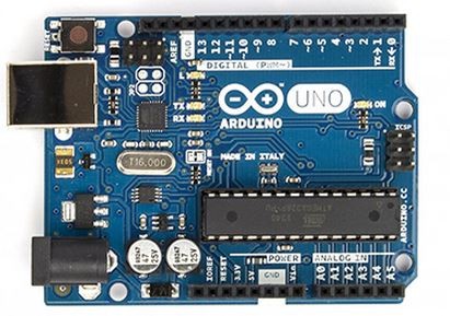
James @ seeed.cc has compiled a list of the most popular Arduino boards including schematics and PCB. You can download the files here.
Arduino is now a very popular open source development board, many people are using the Arduino Development Board to develop interesting, creative product prototypes. Do it yourself DIY Arduino Development Board, isn’t it more fun? Want to DIY Arduino Development Board, must have been around schematics and PCB, speciallycollected 10 Arduino Development Board and expansion board circuit diagram and PCB project files, easy do it yourself DIY, information collected is not easy, let me see and cherish!
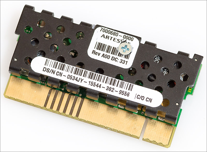
Andy Brown wrote a detailed article on reverse engineering a CPU voltage regulator:
A recent ebay fishing expedition yielded an interesting little part for the very reasonable sum of about five pounds. It’s a voltage regulator module from a Dell PowerEdge 6650 Xeon server.
I originally bought this because I had the idea of salvaging parts from it to use in another project. These are high quality modules that will have very good inductors and sometimes an array of high value ceramic capacitors that could be re-used (ceramics of at least 22µF at 16V and above are rather pricey at the moment). So the VRM arrived and I was rather impressed with the build quality and decided to have a go at reverse engineering it.
Reverse engineering a server CPU voltage regulator module – [Link]
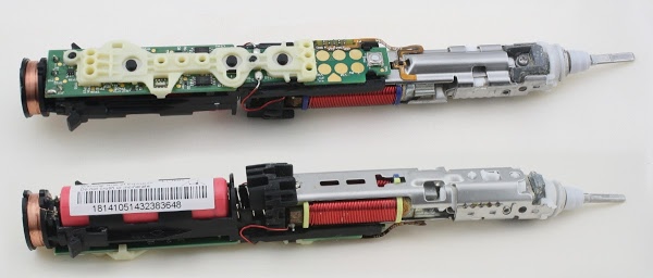
Ken Shirriff did a teardown of a Sonicare electric toothbrush:
The photos below show the top and bottom of the toothbrush internals. I expected to find a simple, low-cost mechanism, so I was surprised at how much complexity there was inside. The vibration mechanism (right) is built from multiple metal and plastic parts screwed together, requiring more expensive assembly than I expected. The circuit board is literally gold-plated and has a lot of components, even if it doesn’t quite reach Apple’s level of complexity. Overall, the toothbrush’s internal design is high quality (except, of course, for the fact that it quit working, as did an earlier one).
Sonicare toothbrush teardown: microcontroller, H bridge, and inductive charging – [Link]
7 Seven segment multi-plexed display is tiny board that has been designed around Common Anode 4 digit Display, Display has 12 Pins. The board is provided with current limiting resistors on all LED segments and 4 PNP Transistors to drive 4 digits, the project is ideal for easy micro-controller interface with 13 pin Header connector. The Board supports 3.3V as well 5V TTL interface.
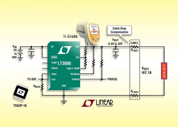
Graham Prophet @ www.edn-europe.com discuss about LT3086 LDO.
The 40V, 2.1A low dropout linear regulator (LDO) includes current monitoring with externally settable current limit and temperature monitoring with external control of thermal limit temperature. The device includes a programmable power-good status flag, cable drop compensation and easy paralleling. The current reference in the LT308x LDO family provides regulation, independent of output voltage.
LT3086 – 40V, 2.1A Low Dropout Adjustable Linear Regulator with Monitoring and Cable Drop Compensation – [Link]