Thomas Scherer @ elektormagazine.com shares the news about a CoolMOS Mosfet from Infineon.
The latest 800V CoolMOS P7 800V MOSFET from Infineon is based on their superjunction technology. The device is available in twelve classes of RDS(on) beginning with 0.28 Ω and in six package options. It is particularly suited to high voltage switching applications, flyback applications including adapter and charger, LED lighting, audio SMPS, AUX and industrial power.
The new 800V CoolMOS MOSFET from Infineon – [Link]
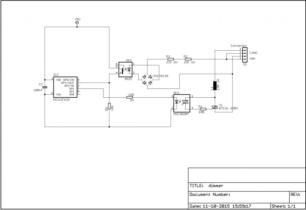
This is a very simple mains isolated dimmer with a triac output (phase control). It uses timer0 to do the timing.
There is no user interface, the value of the triac ignition delay after a zero crossing is defined by setting the reload value of timer0 (Tmr0) in the software directly. This value can e.g. be derived from a user interface or sensor or some algorithm. In the example it is stepped trough a number of values sequentially.
230V AC dimmer, mains isolated, using PIC12F629 – [Link]
This Design Idea presents a low power short circuit finder that capitalizes on the ear’s sensitivity to changes in frequency. The heart of the circuit is a voltage-to-frequency converter (based on Linear Tech’s AN45, Figure 13, by Jim Williams), which converts millivolt-level DC voltages to a wide range audio frequency output.
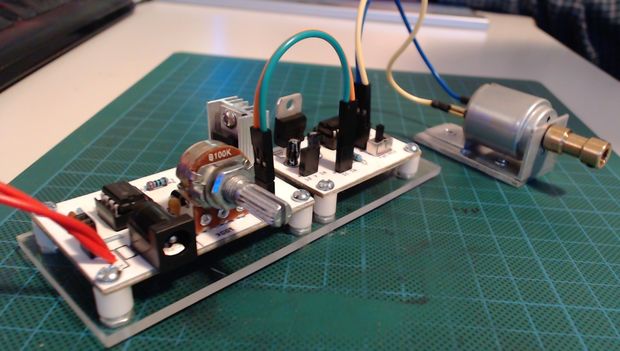
baelza.bubba @ instructables.com show us how to build a DC motor direction controller using L293D.
I designed this DC Motor Direction Controller so that I could give direction control to DC motors that I am building into mini tools (drill, lathe, table saw, solder smoke extractor, etc.). While, I don’t need direction control for all of the tools that I’m building, it IS necessary for some. Plus, who doesn’t want to spin their DC motor backwards?
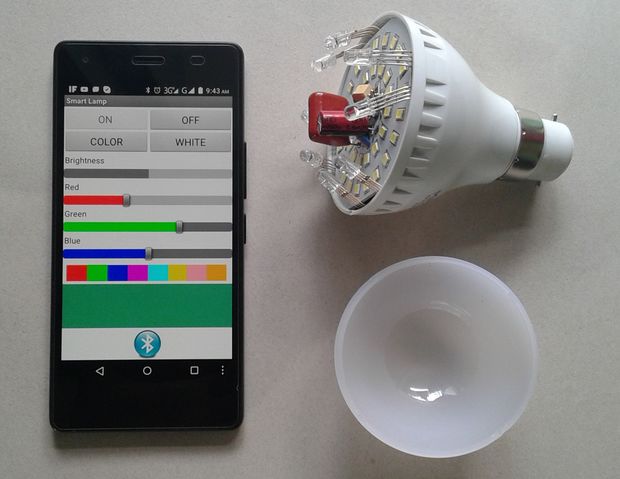
taifur @ instructables.com show us how to convert a simple LED lamp to a smart one that can be controlled using a smartphone.
A smart bulb is an internet or Bluetooth-capable LED light bulb that allows lighting to be customized, scheduled and controlled remotely. Smart bulbs are among the most immediately successful offerings in the growing category of home automation and Internet of Things (IoT) products. In today’s market many types of smart bulbs are available form price $10 to $100. But, can you think you can convert a low price led bulb to a smart bulb easily? Today I will show you how I converted a cheap Chinese led lamp to a Smart Lamp.
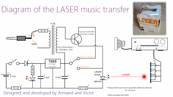
Light is a very popular means of communication. Today, optical fiber communication is the backbone of telecommunication and internet. Light is guided through a fiber optic cable in such systems to achieve low-attenuation and high speed data transmission. Question is: Is it possible to use light for communication without a guiding medium? The answer is positive. Because of the highly collimated nature of the laser beam, it is feasible to use a laser output to transmit information without a guiding medium even in daylight, provided that the line of sight occurs between the sending and receiving units.
Armand & Victor from DIY Experiments Youtube channel illustrates a very simple example of modulating a laser diode output with an analog audio signal and sending it over a distance of more than 400 meters. The laser diode used in this project was of 250 mW capacity, which is ~ 100 times more powerful than a regular laser pointer. A single-transistor class-A amplifier circuit was used to amplify the audio input signal prior to use it for modulating the laser output light. A 1:25 turn ratio transformer is used as a coupling device between the audio and the laser module. The transformer is necessary to ensure only the AC variations (and blocks any DC component) in the audio signal will modulate the laser beam.
Circuit setup for modulating Laser with an audio signal
On the receiving end, the audio is reconstructed back by aiming the modulated laser beam at an array of four mini solar panels. The solar panel output voltage varies according to the signal variation contained in the laser and is directly fed to a high power (250W) guitar amplifier. The audio quality was quite remarkable for such a simple setup. Check out the following demo video of this project:
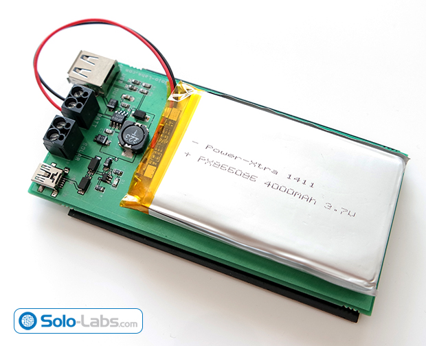
Abdulgafur tipped us with his latest project, a 5V solar powered power bank. The circuit consists of two stages, the first stage is the battery charger stage based on MCP73831 and the second stage is the step up converter based on LT1302-5 which converts the battery voltage to 5V.
Solar energy is renewable, free, widely available and clean form of energy. It is considered as a serious source of energy for many years because of the vast amounts of energy that is made freely available, if harnessed by modern technology. Many people are familiar with so-called photovoltaic cells, or solar panels, found on things like spacecraft, rooftops, and handheld calculators. The cells are made of semiconductor materials like those found in computer chips. When sunlight hits the cells, it knocks electrons loose from their atoms. As the electrons flow through the cell, they generate electricity. In this project, we are building a power bank which harvests energy by using a solar panel.
Smartphones and mobile devices are diving deeply in our lives and make a lot of things much easier than before. So, having a smartphone or a mobile device became one of life’s necessities for everybody. But unfortunately, there is still a big challenge for people with limited use of their arms to use and benefit from these devices.
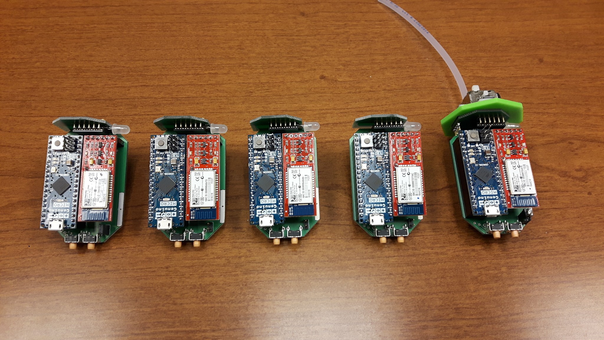
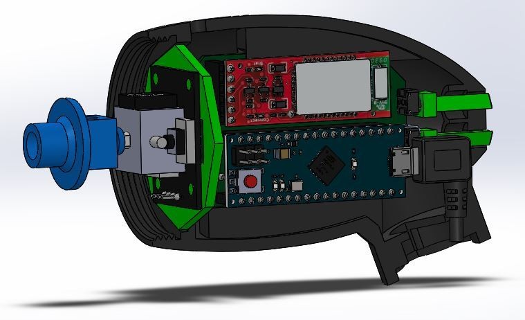
A group of developers tried to help these people and increase their accessibility to the smartphones through “LipSync”. It is an Arduino-based assistive device which aims to increase the ability to use touchscreen devices through a mouth-operated joystick with sip and puff controls.
The developers team, as they mentioned in the project page, focused on creating a robust and easy to build device, designing a device housing which can be 3D printed, and making it flexible for a variety of wheelchairs.
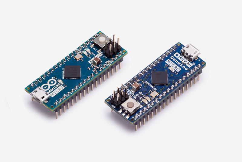
LipSync is based on Arduino Micro, a microcontroller board based on the ATmega32U4 equipped with a Bluetooth module for connecting with the smartphone and send the appropriate instructions.
Arduino Micro – Image courtesy of Arduino.cc
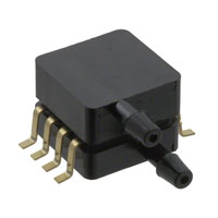
Two main sensors were used in this project. An Analog 2-axis Thumb Joystick used to manipulate a cursor on the device screen, and a Pressure Sensor to catch sip and puf controls and simulate the actions of “tap” and hitting the back button, respectively.
MPXV7002DPT1CT-ND Pressure Sensor – Image courtesy of Digi-Key
In addition to the main control functions, move the cursor, tap, and go back, this device can simulate additional secondary functions such as “tap and drag” and “long tap and drag”.
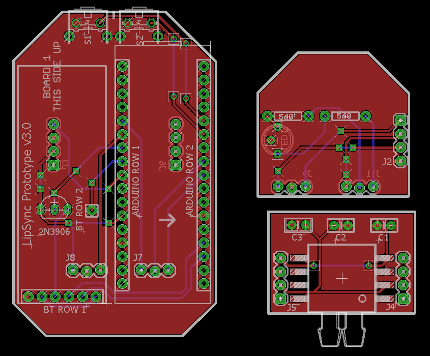
LipSync is an open source project. Schematics and PCB files are available here, but the 3D printer files and arduino code will be made public later.
To read more details about LipSync visit the project page on hackaday.io, where you can follow it and join the development team.
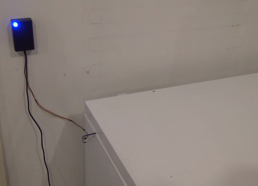
“Arduino Freezer Temperature Sensor” is an Arduino based project which works as an indicator to notify you when the freezer isn’t work properly. This project was created by “John Saunders”.
To make this project, you will need these parts:
Arduino Nano, most of other Arduino boards can be used.
USB cable, to connect the Arduino to the computer.
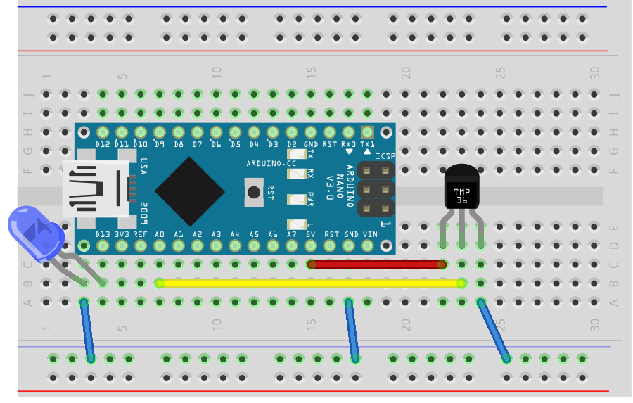
What it is needed is to connect Arduino board , temperature sensor and LED all together. The sensor must be connected to an analog input port, and the LED to a digital output port as shown the figure below:
TMP36 is an easy to use temperature sensor with −40°C to +125°C operation range. It has three pins, supply voltage, output voltage, and ground. The input voltage can be between 2.7 and 5.5 V, so we can connect it with the 5V pin in the Arduino. The output voltage is 0.5V for (0°C) and increases by 10 mV/°C. Here is the full Datasheet.
The next step is preparing the code and uploading it to the Arduino board. The code reads the analog value on its pin, and then convert it to the matching temperature degree. If the temperature is in the normal range, the LED will be on, but if it goes above the threshold, the LED will be turned off.
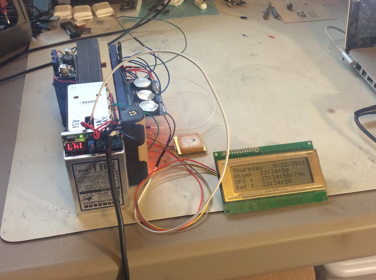
Cameron Meredith build a real-time-clock module controlled by a rubidium frequency standard, and since it also includes a GPS clock he can track local time dilation effects by comparing the two.
An I2C multiplexer board allows for more than one RTC module (Since these have a hard coded I2C address you can normally only use one). I went for three – One tracking GPS time, another tracking the rubidium standard, and the last one as a control or reference clock – without compensation.
An arduino knock-off compares the relative delay between the pulse-per-second outputs from the Rubidium standard, Real Time Clocks, and GPS.
After some defined time divergence, the RTC aging compensation register is updated to refine or maintain overall agreement. Essentially herding the RTCs so that their output stays within bounded agreement with the Rubidium standard and GPS.