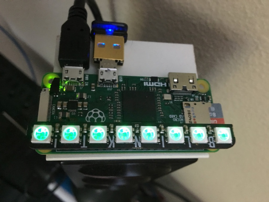
Would you like to monitor all the devices connected to you LAN. Then you can do it using a Rasberry Pi Zero and a few LEDs.
Like most people, we have tons of things connected via WiFi to our router. Be it AppleTVs, Rasberry PIs, Amazon Echos, weather stations, overhead airplane trackers, security cameras, etc. etc. etc…. The problem arises when you think and expect a device to “work” and it doesn’t. Is it the device? Is it the service being accessed? VNC server not running? Most of the time “all is well“, but if it isn’t it can be frustrating. Who knew the security camera was down? Why can’t I VNC into that Raspberry PI? Most of us have been there and this project helps solve the problem.
Keep Tabs on the Devices Connected to Your LAN – [Link]
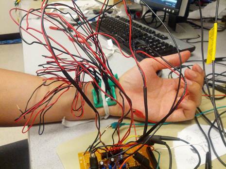
Optomyography is a novel, non-invasive, non-contact optical method to measure muscular signals of the human body for diagnosing muscular disorders. It is also considered as an emerging technique for making better human-machine interfaces. Matt, Amrit, and Maneesh conducted an optomyogram experiment at Cornell University to sense the movement of fingers and wrist, and eventually to detect hand gestures. The underlying principle of this experiment is that when you shine an infrared light on a muscle surface, the amount of light absorbed or reflected back depends on the blood volume underneath the skin. Because the blood volume changes with the contraction of muscles, by measuring the variation in the reflected IR light, it is possible to detect the motion of the muscles.
Optomyography for muscle movement detection
Their sensor unit consists of an infrared emitter and 4 infrared phototransistors arranged in the form of a wrist band. The infrared light emitted by the IR LED is scattered back and is collected by the phototransistors. An Opamp-based instrumentation circuit further filters and amplifies the phototransistor output to obtain nice and clean Optomygram waveform. The amplified signal then goes to a National Instrument’s Data Acquisition System (DAQ) for further processing.
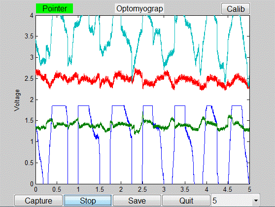
PC application displays optomygram waveform
Their team also developed a PC application based entirely in MATLAB. The application provides a nice graphical user interface and also performs sensor calibration. They also implemented a principal coordinate analysis method for the detection of the finger movements. The GUI not only plots the data from the sensor, but also displays which finger of the user was moved. This project was mostly successful and the designers were able to accurately detect the pointer, middle and thumb. However, with adding more sensors in the future, the system performance can be further improved to detect not only all the fingers but hand movements too.
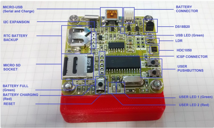
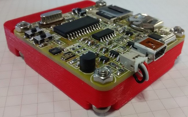
Do you wonder how to build a personal weather station with data logging capability? Well, Jesus Echavarria, a electronic engineer and DIY hardware maker from Spain, has shared the details of his design of a very professional-looking, full-featured, and portable weather data recorder that is capable of recording ambient temperature, humidity, and light level into a SD card along with a time stamp. The datalogger is based on the PIC18F2620 microcontroller and has options to be powered with a rechargeable 3.7V lithium battery as well as from a USB port. It also features a Lithium battery charger circuit on board using Microchip’s fully-integrated MCP73832 Li-Ion charge management controller IC that is configured to provide a charging current of ~200mA. Two on-board LEDs provide visual indications about the battery condition, such as fully charged or under charging.
On the sensor part, the project uses HDC1050 for temperature and humidity measurements, and TEMT6000X01 for ambient light sensing. The time keeping is performed using M41T00SM6 RTC chip with a separate back-up power supplied from a coin-cell battery. Two push buttons and two extra leds used in his design to provide a minimal user interface, and most of the configuration part (like time and date settings) is done through a PC terminal program using a command-line interface. The MCP2221 based USB-UART bridge provides the communication interface between the PC terminal program and the PIC microcontroller. Jesus also shares the design files of the 3D printed case he made for his data logger to get a more professional look.
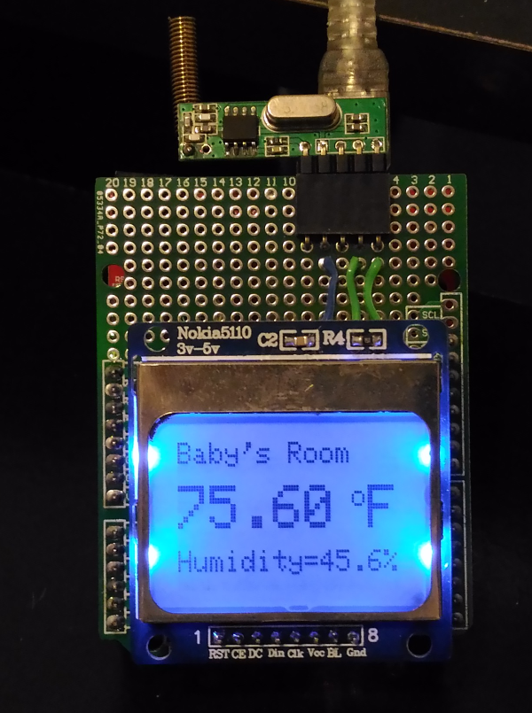
This project describes a DIY wireless temperature and humidity monitor for kids’ or infant’s room using the Arduino platform, and inexpensive and easily available ASK transmitter/receiver modules. On the transmitting end, an Arduino nano senses the ambient room temperature and humidity using the DHT22 sensor and transmits the data to a receiving end Arduino over a 433 MHz ASK RF link. The receiving side Arduino decodes the received bytes and displays the information on a LCD screen. The indoor range of the RF transmission is about 100 ft, which is mostly sufficient for a decent size house.
Wireless temperature and humidity monitor for baby’s room – [Link]
This project describes a DIY wireless temperature and humidity monitor for kids’ or infant’s room using the Arduino platform, and inexpensive and easily available ASK transmitter/receiver modules. On the transmitting end, an Arduino nano senses the ambient room temperature and humidity using the DHT22 sensor and transmits the data to a receiving end Arduino over a 433 MHz ASK RF link. The receiving side Arduino decodes the received bytes and displays the information on a LCD screen. The indoor range of the RF transmission is about 100 ft, which is mostly sufficient for a decent size house.
Things you will need
You will need the following items to build this project.
Two Arduino boards. I am using an Arduino Nano on transmitting side and Arduino Unoon receiving end.
One Nokia 5110 LCD for displaying data at the receiving side
One DHT22 sensor for measuring temperature and humidity at the transmitting en
Two LEDs and two 330Ω resistors
Wires, breadboard, prototyping board, etc.
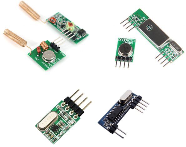
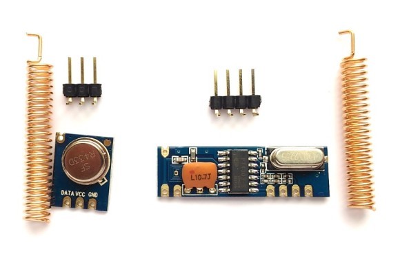
Few words on ASK RF kits
There are varieties ASK Tx/Rx modules available online in both domestic and international markets (specially China). Some of them come with spring antennas, and some don’t. With the ones without antennas, you can connect ~20cm wire to their antenna pin on circuit board. The figure below shows some of the ASK RF modules you can buy on eBay and Amazon.
For this project, I used high quality ASK RF modules manufactured by NiceRF, a China-based company. You can also buy these modules directly from our Tindie store. The nice things about these modules are they are very compact, breadboard and PCB friendly, made of high-quality PCB, come with copper spring antennas and have a reasonable transmission range.
Hardware setup on transmitting end
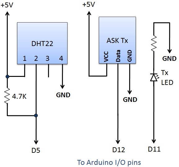
The ASK transmitter module has three pins: VCC, Data, and Gnd. They could be in different sequence depending upon the manufacturers. So, always read the pin labels carefully to identify the data and power supply pins on these modules. The VCC and Gnd pins are connected to +5V and Gnd pins of Arduino Nano, whereas the Data pin of the Tx module goes to digital I/O pin 12 of Arduino. An LED is also connected to I/O pin 11 along with a current limiting resistor in series. During data transmission, this LED is turned on.
Tx Circuit (resistor in series with the LED is 330 Ohm)
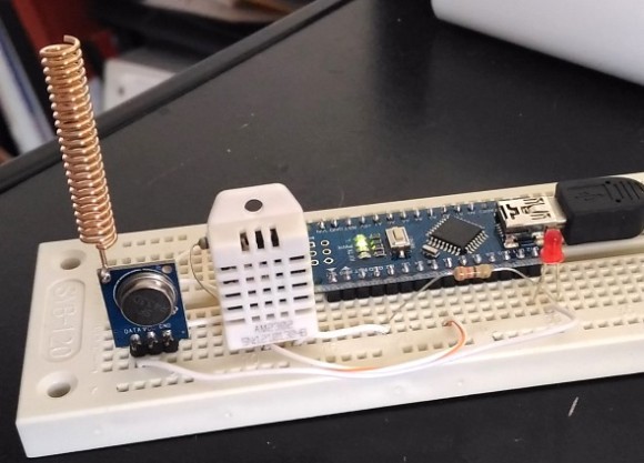
The above circuit is wired up on a breadboard as shown below.
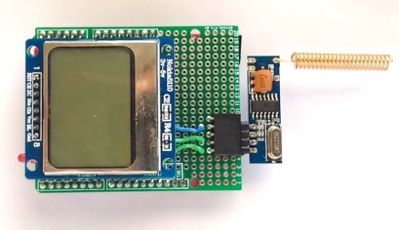
Circuit setup: Rx End
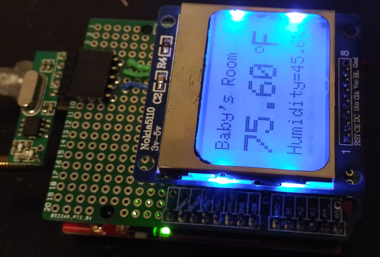
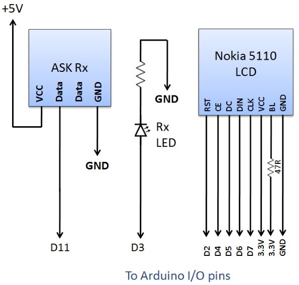
The Rx module also consists of VCC, Gnd, and Data pins. Some modules may have more than one Data pin. In such case, you can use any one of them as they are all connected together. On the receiving side, the Data pin of the Rx module output and is read by an Arduino pin. In our case, it is connected to the D11 pin of Arduino. Similar to the Tx end, an LED connected to D3 pin is an indicator of receiving the data sent by the transmitter. A Nokia 5110 LCD is also connected to the receiving side Arduino to display the temperature and humidity at the remote station. For this experiment, I am using Crowduino Uno (Arduino Uno clone) on the receiving side.
Please note that Nokia 5110 LCD operates at 3.3V. I am running my Crowduino Uno board at 3.3V so it does not matter in this case. If your Arduino board operates at 5.0V, you would need a voltage shifter in between the Arduino and the LCD. The following diagram shows the connections at the receiving end in more detail.
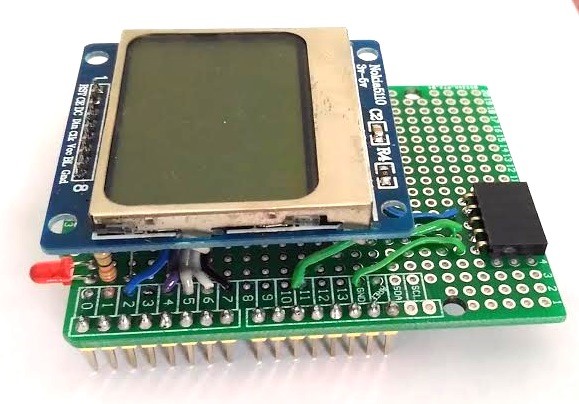
I used a general purpose Arduino proto-shield to build the above circuit. Following figure shows the assembled receiver circuit soldered on the Arduino proto-shield.
Receiving module with ASK receiver plugged in
Software
This project uses the VirtualWire library for Arduino written by Mike McCauley. This library supports numerous low-cost RF transmitters and receivers available in the market and allows to send short messages through ASK modulation. In this project, the Arduino on Tx end reads temperature and humidity from the DHT22 sensor, combines the two readings into a character string, and send it over the RF link. On the receiving end, the Arduino extracts the two readings back from the received string and displays the data on the Nokia 5110 LCD. You can download the VirtualWire library and Arduino codes for Tx and Rx ends from the following links.
After uploading the firmware to two Arduino boards, the project is ready for testing. You can place the Tx module to the place where you would like to monitor the temperature and humidity remotely and place the Rx module within a 100ft range. You should see the measured values on the LCD screen as shown below:
This project can be further expanded by adding a buzzer to the Rx end and programming the Arduino to alarm when the temperature and/or humidity falls outside preset limits.
I sell these Tx and Rx modules as a kit at our Tindie store. If you are interested to get one, click the following link:
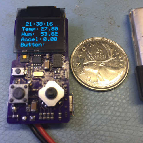
Mike Rankin created this tiny sensor board with an ARM Cortex M0+ microcontroller and OLED display:
It’s pretty tiny so a 4 layer board made the whole job easier. The top and bottom are pretty much dedicated for components, layer1 are tracks and power traces, layer2 is a ground plane. Mixing up an internal plane and routing layer was interesting.
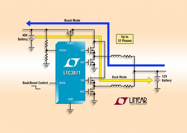
LTC3871 is a 100V/30V bidirectional two phase synchronous buck or boost controller, for 48V/12V automotive dual battery systems; it provides bidirectional DC/DC control and battery charging between the 12V and 48V boardnets, operating in buck mode from the 48V bus to the 12V bus or in boost mode from 12V to 48V. by Graham Prophet @ edn-europe.com
The LTC®3871 is a high performance bidirectional buck or boost switching regulator controller that operates in either buck or boost mode on demand. It regulates in buck mode from VHIGH-to-VLOW and boost mode from VLOW-to-VHIGH depending on a control signal, making it ideal for 48V/12V automotive dual battery systems. An accurate current programming loop regulates the maximum current that can be delivered in either direction. The LTC3871 allows both batteries to supply energy to the load simultaneously by converting energy from one battery to the other.
48V/12V DC/DC for automotive dual-rails offers bidirectional power flows – [Link]
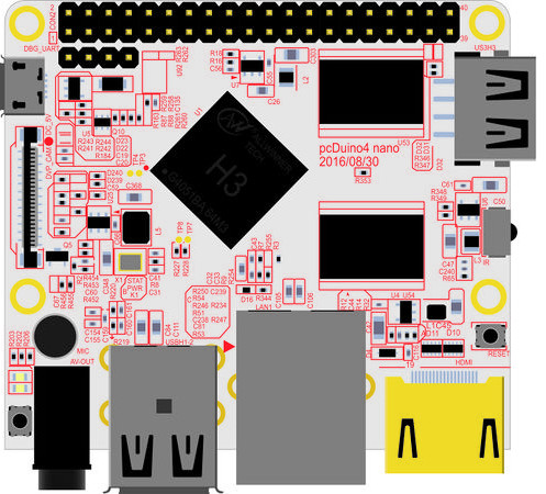
A new low cost development board is available for pre-ordering at $20, it is called “pcDuino4 Nano”. pcDuino term comes from combining Mini PC with Arduino and it is a platform that runs PC-like OS such as Android ICS or Ubuntu.
pcDuino boards can be used to learn programming and understand how to use linux OS. It also works as an interface with electronics hardware alongside the typical activities such as browsing internet and watching movies.
pcDuino4 Nano based on Allwinner H3 SoC, which has a 1.2 GHz quad core Cortex A7 CPU 512KB cache, with an ARM Mali-400MP2 GPU up to 600 MHz. This chip supports DDR2 and DDR3 memories, Ultra HD 4k and Full HD 1080p video decoding, camera and audio integration.
pcDuino4 Nano comes with 1GB RAM memory, microSD card slot, USB 2.0 and micro USB ports, HDMI port, 3.5mm jack, 10/100 M ethernet, DVP interface, pin headers for expansions and powered by 5V.
Here is the full specifications:
SoC – Allwinner H3 quad core Cortex A7 @ 1.2 GHz with an ARM Mali-400MP2 GPU up to 600 MHz
System Memory – 1GB DDR3 SDRAM
Storage – microSD card slot
Video & Audio Output – HDMI and 3.5mm jack for CVBS (composite + stereo audio)
Connectivity -10/100M Ethernet
USB – 3x USB 2.0 host ports, 1x micro USB OTG port
Camera – DVP Interface
Expansions – 40-pin Raspberry Pi compatible header with UART, SPI, I2C, PWM, GPIOs, etc…
Debugging – 4-pin header for serial console
Misc – Power and reset buttons; 2x LEDs; IR receiver; on-board microphone.
Power Supply – 5V/2A via micro USB port; 4.7V ~ 5.6V via VDD pin on “Raspberry Pi” header.
Dimensions – 64 x 50mm (smaller than Arduino UNO and Raspberry Pi)
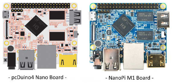
You might notice that this board is very similar to another one called “NanoPi M1”. They have the same design, features, ports and schematic and according to CNXSoft the manufacturer is the same. The main difference we can detect is that pcDuino4 has a white PCB and the other has a blue one.
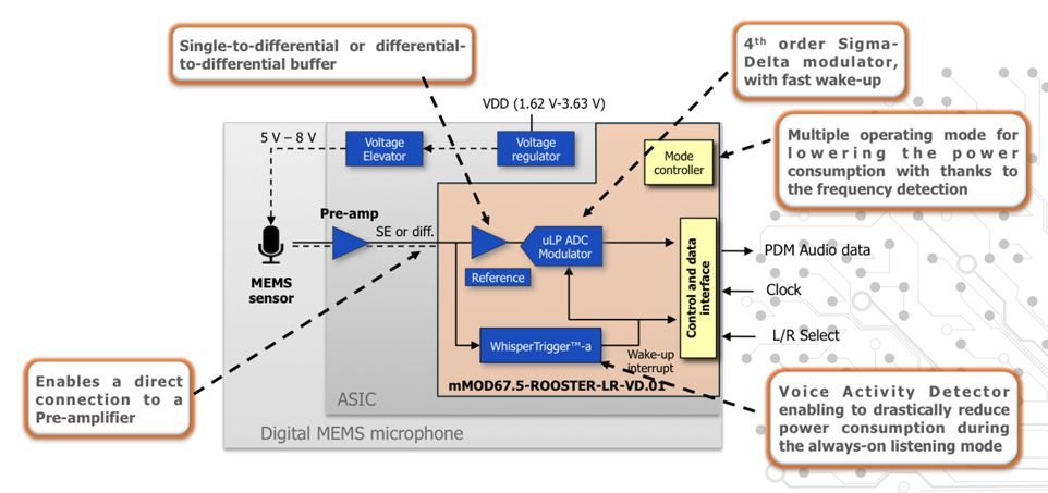
For long period of time, we were using our muscles and bodies to control various machines. However, with the growth of technology, things became much easier. We moved to the use of keypads and buttons to get jobs done. Today, touchscreens have appeared and made everything very simple to use. But we did not get enough, and the near future will be for the voice commands.
Using voice commands implies the need to use detection systems and circuits, which must provide high accuracy results, reliable at both near and far distances, not affected by noise, simultaneously sensitive, fast, and also have low power consumption. Power consumption is very important factor nowadays, especially with the application of Internet of Things (IoT) devices which are powered using batteries and have to work for long time.
Most of current solutions for voice recognition use digital signal processors (DSPs) connected with A/D converters and they work in permanent wake mode which make them consume high amounts of power in case of IoT applications and smartphones.
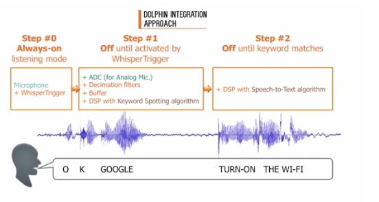
The conventional Approach
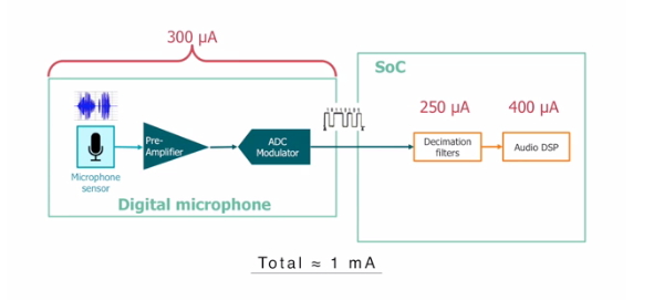
Dolphin Integration, a French corporation works on enabling low-power Systems-on-Chip and provides a solution called “Whisper Trigger”, an ultra-low power voice detector with outstanding performance of detection, enabling wake-up voice acquisition and recognition when needed. In comparison with other devices, this technology reduces power consumption by 80-90%. It consumes only 20 µA, and needs just 1 millisecond to wake up.
Dolphin Integration provides also another solution for text recognition and detection of keywords, the Microelectromechanical System (MEMS) which should be connected to DSP and circular buffer to perform the process of conversion, decimation and filtering.
SnapEDA launched a new on-demand PCB symbols service. Get any schematic symbol and PCB footprint delivered in 24 hours. Just $29
SnapEDA follows IPC-7351B standards for its footprints, and a combination of IEEE-315 and its own standards for symbols.
All models are created by our component engineering team and verified using proprietary patent-pending verification technology as part of a three-step verification process.
SnapEDA launches on-demand PCB symbols service – [Link]