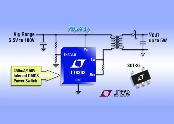
LT8303 is a monolithic flyback regulator in a TSOT-23 package that simplifies the design of isolated DC/DC converters. By sampling the isolated output voltage directly from the primary-side flyback waveform, the part requires no opto-isolator, LT1431 or third winding for regulation. by Graham Prophet @ edn-europe.com
The LT8303 operates over a 5.5V to 100V input voltage range, has a 0.45A/150V integrated DMOS power switch and delivers up to 5W, suiting it for a range of telecom, datacom, automotive, industrial, medical and military applications. The output voltage is set with one external resistor and the transformer turns ratio. Several off-the-shelf transformers are identified in the data sheet. The LT8303 operates in boundary mode, which is a variable frequency current mode control switching scheme, typically resulting in ±5% output voltage regulation over the full line, load and temperature range. Boundary mode enables the use of a smaller transformer compared to equivalent continuous conduction mode designs. The high level of integration and the use of low ripple Burst Mode operation result in a simple to use, low component count and high efficiency application solution for isolated power delivery.
100Vin, 5W out regulator uses primary-side control – [Link]
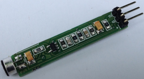
The single supply microphone pre-amplifier amplifies the output signal of an electret capsule microphone to audio line levels. An op amp is used as a trans-impedance amplifier to convert the output current from the microphone in to a signal level voltage. The circuit works with 9V so it is good choice for battery operated systems.
Features
Supply 9V DC
Current Approx. 3mA
On Board Microphone
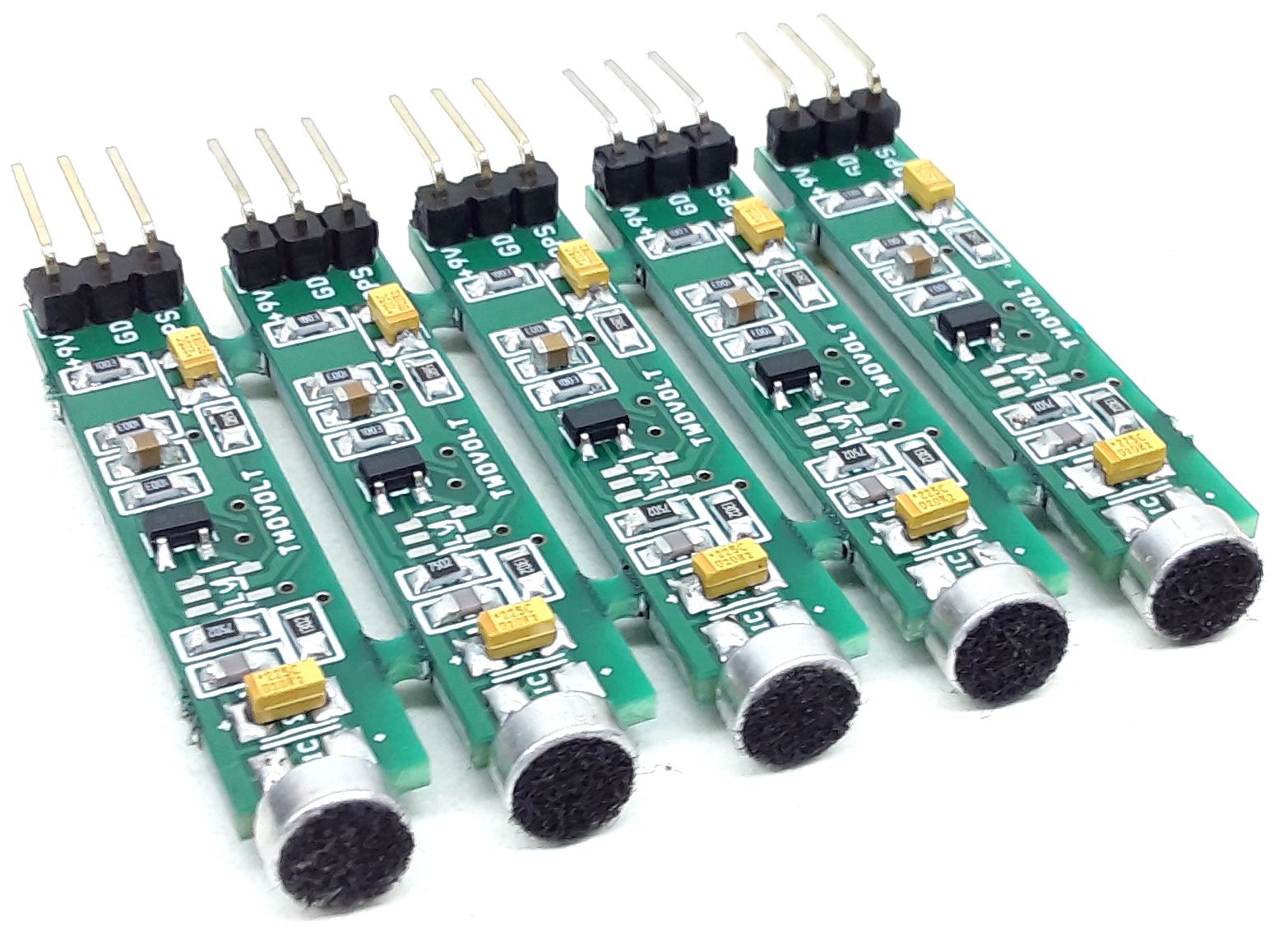
Very thin and narrow PCB
Low noise Mini Electret Microphone PreAmplifier – [Link]
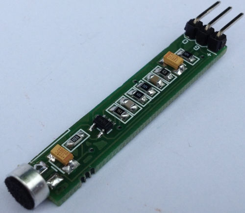
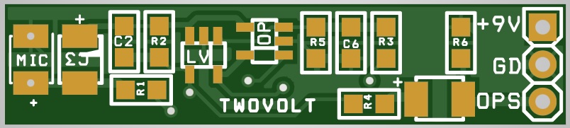
This single supply microphone pre-amplifier amplifies the output signal of an electret capsule microphone to audio line levels. An op-amp is used as a trans-impedance amplifier to convert the output current from the microphone into a signal-level voltage. The circuit works with 9V so it is a good choice for battery-operated systems.
Features
Supply 9V DC
Current Approx. 3mA
On-Board Microphone
Very thin and narrow PCB
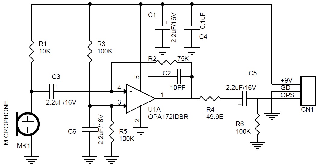
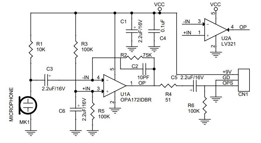
Schematic
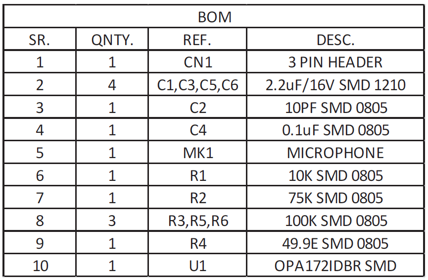
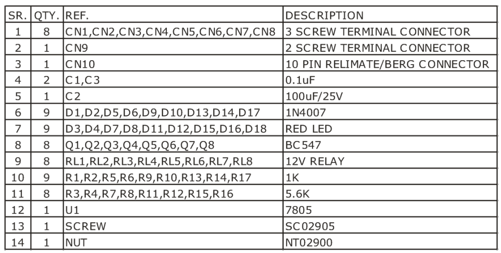
Parts List
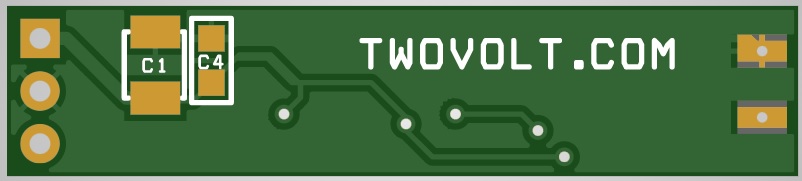
Version v.2 with LV321
This v.2 of the above-board provides an additional option to use LV321 OPAMP in case you can’t find the OPA172. The board has two OPAMP footprints, and you should solder only one. If you use LV321 OPAMP, then the maximum input Vcc=5Vdc. If you use OPA172 OPAMP, then the maximum input Vcc=36Vdc.
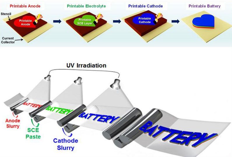
A new type of batteries called “Printable Solid-State (PRISS) Lithium-Ion Batteries” was designed by a group of researchers from the Ulsan National Institute of Science and Technology (UNIST, South Korea). The new battery is created from consecutive layers of printed composite materials.
Representation of the PRISS Battery production process
With a simple stencil printing process followed by ultraviolet cross-linking, a solid-state composite electrolyte (SCE) layer and SCE matrix-embedded electrodes are consecutively printed on arbitrary objects of complex geometries, eventually leading to fully integrated PRISS batteries. Then the rheological properties of SCE paste and electrode slurry adjusted to get thixotropic fluid characteristics, along with well-designed core elements.
This technology yields many positive features, it eliminates the need for conventional microporous separator membranes and the extra processing steps of solvent drying and liquid-electrolyte injection.
With this new type of batteries, unlimited forms and sizes of batteries will be available for our various projects.
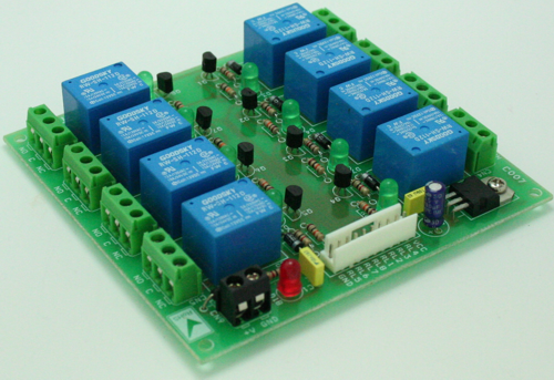
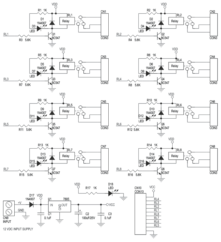
This is a general purpose relay board accepting 8 inputs to drive 8 relays providing control requirement in your project. This board can also be used as an add-on card for the various Development board that we provide and various microcontroller boards.
Features
Robust Design using NPN transistor to drive each relay
Relay On Indicator LED for each of the eight relays.
Back EMF / Surge protection diode across each relay to protect driving circuit.
3 Pin PBT connector for connecting load to the relay.
Reverse Polarity protection diode (D17) provided.
2 pin PBT provides easy connection of power source to the PCB.
On Board Voltage Regulator U1 (7805) provides +5V DC supply to ongoing interface circuit connected to this board.
A 10 pin Relimate Connector provides easy connect of this PCB to the driving interface.
Supply voltage 12 ~ 15 V DC
8 Channel Relay Board with onboard 5V regulator – [Link]
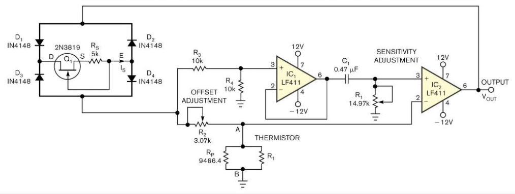
by S Kaliyugavaradan, Anna University, Madras Institute of Technology, Chennai, India; Edited by Brad Thompson and Fran Granville -November 10, 2005
Designers often use thermistors rather than other temperature sensors because thermistors offer high sensitivity, compactness, low cost, and small time constants. But most thermistors’ resistance-versus-temperature characteristics are highly nonlinear and need correction for applications that require a linear response.
Temperature-to-period circuit provides linearization of thermistor response – [Link]
The pi-top converts your Raspberry Pi into a complete RPi notebook. by René Bohne @ elektormagazine.com
It comes as a nice kit that is very easy to assemble thanks to a great construction manual. We created a video of the assembly. If you have any questions, feel free to leave comment on Youtube or below this article!
Review: pi-top DIY laptop for your Raspberry Pi – [Link]
In this video educ8s.tv shows us how to use the Color OLED display with the SSD1331 driver with Arduino. It’s very easy!
A few weeks ago, I discovered this promising new display on Banggood.com and I thought that it might be useful in some of our projects so I bought it right away. It is a Color OLED display! I have used this small monochrome OLED display in some of my previous projects and I love it. So, I couldn’t resist having a color OLED display. I have loaded a demo sketch and as you can see the display is fast and bright. It is brighter than LCD displays because it uses the OLED technology and of course it uses less power. The power usage will vary with how many pixels are lit, the maximum is around 25mA. The cost of this color OLED display is around $11.
Arduino Tutorial: Color OLED SSD1331 display with Arduino Uno – [Link]
This is a general purpose relay board accepting 8 inputs to drive 8 relays providing control requirement in your project. This board can also be used as an add-on card for the various Development board that we provide.
Features
Robust Design using NPN transistor to drive each relay
Relay On Indicator LED for each of the eight relays.
Back EMF / Surge protection diode across each relay to protect driving circuit.
3 Pin PBT connector for connecting load to the relay.
Reverse Polarity protection diode (D17) provided.
2 pin PBT provides easy connection of power source to the PCB.
On Board Voltage Regulator U1 (7805) provides +5V DC supply to ongoing interface circuit connected to this board.
A 10 pin Relimate Connector provides easy connect of this PCB to the driving interface.
Omniblox, the Eagle .brd 3D viewer we previously covered here has released a new version that uses fonts and corrects rotation issues in silk screens. Code and instructions available on github.